


اسأل أي مهندس كهربائي عن الجهاز المستخدم لحماية نظام ثلاثي الطور من الأعطال الأرضية والتيار المتسرب، وستكون الإجابة على الأرجح هي محول تيار توازن النواة (CBCT)، والذي يُشار إليه أيضًا بمحول تيار التسلسل الصفري (ZCT) أو محول تيار الطور الصفري. يُعتبر CBCT حلقة حلقية تسمح بمرور الموصلات الثلاثة الطور وموصل الأرض، إذا تم استخدامه، من خلالها في جميع الأوقات مع مراقبة مجموع التيارات وبالتالي منع أي قياس خاطئ من خلال تتبع أي طور واحد فقط. يتحقق CBCT من أن التيارات الثلاثة الطور تلغي بعضها البعض إلى الصفر أثناء التشغيل العادي، وتنتهي سلامة CBCT في اللحظة التي تحدث فيها أي تيارات متسربة أو أعطال أرضية في النظام. يسجل CBCT أي تيار غير صفري (متبقي) ويرسل إشارة قطع إلى مرحل تسرب الأرض من خلال لفائفه الثانوية، مما يمكّنه من العمل في غضون مللي ثوانٍ. وبالتالي، فإن إدخال CBCT في القطاع الصناعي يوفر تدبيرًا وقائيًا ضد المناطق غير القابلة للوصول للهندسة الكهربائية.
في هذه المقالة، سيتم تعريف CBCT من حيث التشغيل، مع تسليط الضوء على طريقة عمله، وتحديد الأنواع المتاحة للاستخدام، وتحديد مجالات الاستخدام، وتحديد الفروق لتمييز CBCT عن نظام محول التيار التقليدي، ومناقشة الشركات المصنعة، وتحليل التكلفة.
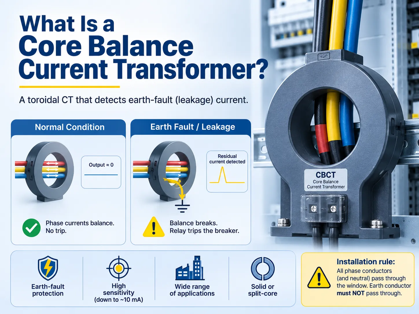
إجابة سريعة: محول تيار توازن النواة (CBCT)، والذي يُطلق عليه أحيانًا محول تيار التسلسل الصفري (ZCT) أو محول تيار الطور الصفري (ZPC)، هو في الواقع محول تيار حلقي يمر عبر جميع الأطوار الثلاثة. في الظروف العادية، يؤدي المجموع المتجه للتيارات في الأطوار الثلاثة إلى تدفق صافي صفر في النواة، مما ينتج عنه إخراج صفر فولت في هذه الحالة. ومع ذلك، إذا حدث عطل أرضي أو إذا كان هناك تسرب للتيار، يتم كسر التوازن ويتدفق تيار متبقي عبر النواة، مما يجعل من الممكن لـ CBCT إرسال إشارة إلى مرحل العطل الأرضي أو مرحل التسرب لقطع النظام في حالة اكتشافه تيار تسرب لا يتجاوز بضع مللي أمبير.
ما هو محول تيار التوازن الأساسي؟
محولات تيار توازن النواة (CBCT) فريدة ومصممة خصيصًا، حيث تأخذ شكل حلقات، والتي تحتوي على لفائف ثانوية مصنوعة فوقها. يتم إدخال الموصلات الثلاثة الطور من النظام ثلاثي الطور (أي إما ثلاثة كابلات أحادية النواة أو كابل ثلاثي النواة واحد) من خلال الثقب المركزي للحلقة وتعمل كلفائف أولية للمحول. لا يقيس عمل CBCT الأطوار الفردية؛ بل يقيس المجموع المتجهي لكل شيء داخل الحلقة. في نظام ثلاثي الطور متوازن، يكون هناك مجموع صفري للكمية المتجهة مما يعطينا إخراج ثانوي صفري لدائرة صحية. أي عدم توازن مثل عطل تسرب سيؤدي إلى إخراج ثانوي يتم حقنه في مرحل العطل الأرضي (EFR) أو مرحل تسرب الأرض (ELR)، الذي يقوم بتشغيل قاطع الدائرة.
نفس الجهاز له العديد من الأسماء المختلفة وهي محول تيار توازن النواة، محول تيار التسلسل الصفري (ZCT)، محول تيار المرحلة الصفرية (ZPC) ومحول تيار التسرب المتبقي (RCT) التي تدل على نفس النوع ومبدأ العمل. تشير معظم أجزاء العالم إلى هذا الجهاز باسم CBCT. عائلة منتجات محولات التيار الكاملة التي ينتمي إليها مغطاة في محول التيار .
كيف يعمل: مبدأ التسلسل الصفري
يعتمد مبدأ العمل وراء ذلك على قانون كيرشوف للتيارات في المغناطيسية. في حالة نظام ثلاثي الطور عادي،,
IA + IB + IC = 0
حيث تصل جميع تيارات الطور الثلاثة إلى أعلى قيمة لها في نفس الوقت ولها زاوية إزاحة قدرها 120°، فإن مجموع هذه التيارات الطورية يساوي صفر. وهذا يعني أن التدفقات المغناطيسية الناتجة عنها داخل الشكل الحلقي تتوازن تمامًا مما يؤدي إلى صفر صافي تدفق وعدم وجود تيار ثانوي. وبالتالي، يبقى جهاز حماية الأرض غير نشط. وهكذا، نرى مفهوم توازن النواة، حيث يساعد مجموع التيارات الصفري في الحفاظ على توازن النواة الحلقي.
عندما يحدث عطل أرضي أو تسرب - إما عندما يتصل أحد الأطوار بغطاء المعدات أو عندما يدخل الرطوبة إلى المعدات، فلن يعود التيار عبر الأطوار إلى المصدر وسيتخذ جزءًا من الدائرة مما سيؤدي إلى إزعاج التوازن.
IA + IB + IC ≠ 0
يُطلق على المتبقي اسم تيارات التسلسل الصفري التي تتدفق إلى نواة الحلقة مما يخلق تدفقًا صافيًا ويولد تيارًا ثانويًا في الملف. يكشف جهاز حماية الأرض عن هذا التيار ويأمر بتشغيل قاطع الدائرة تقريبًا على الفور.
الأنواع والبناء
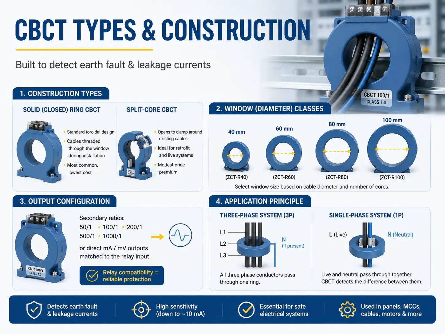
تصنيف CBCTs يعتمد أساسًا على بنائها وحجم النافذة، وليس على الطوبولوجيا الكهربائية:
- حلقة CBCT صلبة (مغلقة) - التصميم الحلقي التقليدي حيث يتم تمرير الأسلاك عبر النافذة أثناء التركيب - الأكثر اقتصادية والأكثر استخدامًا.
- CBCT ذو النواة المنقسمة - هذا النوع من CBCT يفتح ليحيط بالأسلاك الموجودة دون الحاجة إلى فصلها - يُستخدم عادةً لتحديث الدوائر الكهربائية الموجودة بسبب قيود العمل داخل دائرة حية.
- فئات النافذة/القطر - يجب أن يكون قطر الثقب المركزي مناسبًا لحزمة الأسلاك المارة من خلاله؛ الأحجام النموذجية للثقوب هي 40 مم، 60 مم، 80 مم، و100 مم أقطار اسمية، اعتمادًا على حجم الموصلات (مثل ZCT-R40، R60، R80).
- تكوين الإخراج - فائدة كبيرة من CBCTs هي توفر نسبة ثانوية مثل 50/1، 100/1، 200/1، 500/1، أو 1000/1 مخرجات ثانوية؛ تطابق مواصفات الإخراج مع المدخلات على جهاز الحماية - تأتي العديد من أجهزة الحماية متزاوجة مع CBCTs مصنعة من نفس الشركة مما يضمن التوافق.
في الأنظمة ثلاثية الطور، يتم قياس جميع الأطوار الثلاثة من خلال حلقة واحدة؛ في الاستخدام أحادي الطور، تمر الأسلاك الحية والمحايدة عبر الحلقة معًا للسماح بقياس عدم التوازن في الدائرة. يتبع اختيار النسبة وفئة الدقة لأي من هذه التكوينات الدليل العام لاختيار محولات التيار.
CBCT مقابل CT التقليدي: الاختلافات الرئيسية
| الميزة | محول توازن النواة (CBCT/ZCT) | محول التيار التقليدي (CT) |
|---|---|---|
| ما يقيسه | مجموع المتجهات (المتبقي) لجميع التيارات عبر الحلقة | تيار الحمل لموصل واحد |
| التركيب | جميع الأطوار (والحيادي) تمر عبر حلقة واحدة | محول CT واحد لكل طور على الموصل |
| الناتج في التشغيل العادي | صفر (نظام متوازن) | تيار الحمل الكامل (مقاس) |
| الغرض الأساسي | كشف عطل الأرض / تسرب الأرض | القياس وحماية التيار الزائد |
| الحساسية تجاه أعطال الأرض | عالية جداً — ملي أمبير | محدودة — مصممة لتيارات الحمل الكامل |
| الأعطال المكتشفة | أعطال الأرض، التسرب، التسلسل الصفري | الأحمال الزائدة، الدوائر القصيرة، تيار الطور |
النتيجة العملية هي أن محول CT التقليدي يعطيك تفاصيل عن مقدار التيار الذي تحمله طور معين بينما يشير CBCT إلى أي تيار مفقود، وهو التيار الذي تسرب إلى الأرض. الاثنان تكميليان، وليس متنافسين: تستخدم المصانع محولات CT للقياس وحماية التيار الزائد وCBCT لطبقة حماية أعطال الأرض التي لا تستطيع محولات CT رؤيتها — أساسيات تصميم حماية أعطال الأرض ملخصة في أساسيات حماية أعطال الأرض مقالتنا.
أين تُستخدم CBCTs
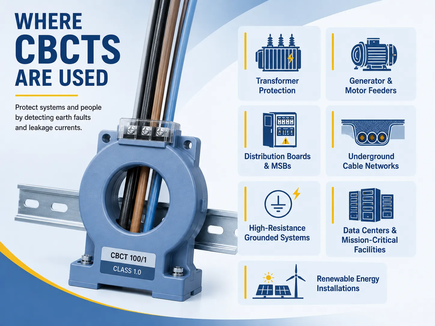
- حماية المحول — حماية أعطال الأرض على المحولات الحيادية وكذلك على الملفات، بما في ذلك مخططات عطل الأرض المقيد (REF).
- مغذيات المحركات والمولدات — حماية حساسة لأعطال الأرض على مغذيات المحركات ولوحات MCC (يمكن أن يتسبب التسرب الصغير في تلف ملفات المحرك).
- لوحات توزيع صناعية وMSBs — تركيب مرحل عطل الأرض على لوحة المفاتيح الرئيسية وفي لوحة التوزيع.
- شبكات الكابلات تحت الأرض — حيث يصعب العثور على العطل في كابل ويكون الكشف المبكر عن العطل ضرورياً.
- الأنظمة ذات الأرضية عالية المقاومة — في هذه الحالة، تكون حساسية الملي أمبير هي المتطلب المطلوب.
- مراكز البيانات والمرافق الحرجة — يجعل كشف التسرب من الممكن تجنب التوقف بسبب العطل.
- أنظمة الطاقة المتجددة — حماية تسرب الأرض لنظام مدعوم من العاكس.
قواعد التركيب والأخطاء الشائعة
الخبرة المكتسبة في الميدان متسقة عبر تركيبات مختلفة لمحول تيار توازن النواة (CBCT) - يمكن أن تنجح التركيبات أو تفشل اعتمادًا على الالتزام بالقواعد التالية:
- يجب أن تمر جميع الموصلات الطورية عبر نواة CBCT - كل موصل يحمل تيارًا والذي يُقصد بالكشف عن تسربه بواسطة CBCT (أي الموصل المحايد إذا كان موجودًا في التركيب).
- يجب ألا يمر موصل الأرض أو الأرض عبر نواة CBCT - في تركيب يمر فيه موصل الأرض عبر النواة، فإن أي تيار عطل في موصل الأرض يلغي عدم التوازن الذي يسعى CBCT للكشف عنه، وهو خطأ في التركيب يحدث بشكل متكرر ويجعل التركيب غير فعال.
- يجب أن تكون كابلات الموصلات مركزة عبر نواة CBCT من أجل تقليل الأخطاء التي يمكن أن تنتج عن وضع الكابلات بشكل غير مركزي.
- يجب التحقق من القطبية الصحيحة - يجب أن تتطابق الاتصالات على الجانب الثانوي مع اتصالات الإدخال لمرحلة CBCT لكي تعمل الوحدة.
- يجب استخدام درع وتأريض كافيين - هذا يمنع التداخل الكهرومغناطيسي غير المرغوب فيه من الموصلات المجاورة من بدء انقطاع غير مرغوب فيه.
سيؤدي تركيب ينتهك الإرشادات من خلال وجود موصل الأرض يمر عبر نواة CBCT أو متصل بقطبية خاطئة إلى فشل النظام في الكشف عن التسرب أو إلى انقطاعات غير مرغوب فيها مستمرة، وكلاهما يمكن اكتشافه من خلال اختبار التكليف والتدقيق الميداني. رفيق الاختبار الكهربائي لتكليف CBCT - فحص العزل، والقطبية، وتنسيق المرحلات - هو نفس الانضباط كما هو الحال في أي مخطط حماية محول، ومعايير القبول مدرجة في اختيارنا: اختبار المحولات لدينا.
الاختيار: مطابقة CBCT مع النظام
يتضمن اختيار CBCT المناسب أخذ أربعة معايير في الاعتبار:
- جهد النظام. بالنسبة للوحة التوزيع، اختر CBCT منخفض الجهد (0.66 كيلوفولت). بالنسبة لمغذيات معدات التبديل، اختر CBCT متوسط الجهد (حتى 33 كيلوفولت) يلبي متطلبات العزل المناسبة.
- قطر النافذة. يجب أن تكون النافذة كبيرة بما يكفي لاستيعاب حزمة الكابلات. قم بقياس كابلاتك الفعلية وتأكد من وجود سعة إضافية متاحة قبل اختيار قطر إما 40 مم، 60 مم، 80 مم، أو 100 مم.
- الحساسية والنسبة. تأكد من أن الحد الأدنى من تيار الكشف ونسبة الإخراج (أو إخراج الميلي أمبير/الميلي فولت) تلبي متطلبات إدخال مرحل عطل الأرض. الطريقة الأكثر أمانًا هي اتباع قائمة توافق الشركة المصنعة للمرحلات.
- البناء. يجب أن يحتوي البناء على حلقة صلبة للتركيبات الجديدة، ولكن نواة مقسمة تقلل بشكل كبير من الوقت المطلوب للتركيب في نظام حي.
ستحدث هذه الاختيارات الأربعة الفرق بين مخطط عطل الأرض الذي سيكتشف عطلًا بقوة 500 مللي أمبير ومخطط عطل الأرض الذي لن يكتشف أي عطل على الإطلاق.

الشركات المصنعة والأسعار
سوق CBCT مغطى بشكل رئيسي من قبل مصنعي المرحلات الحماية والمصنعين الكهربائيين العامين. الشركات الرائدة في هذا السوق هي Honeywell وABB وSchneider Electric وMikro (المعروفة بـ CBCT الخاصة بها، المباعة مع مرحلات تسرب الأرض)، بالإضافة إلى عدد قليل من مصنعي CTs الموجودين في السوق منذ أن بدأت الصين في إنتاج CBCTs ذات النواة الصلبة والنواة المنقسمة بأسعار مباشرة من المصنع. نظرًا لأن CBCTs تُباع في الغالب مع علامة تجارية واحدة من المرحلات، فإن إجراء الشراء يكون كالتالي: يختار المشتري أولاً المرحل ثم يبحث عن CBCT المناسب. في بعض الحالات، يمكن للمستخدم شراء حزمة كاملة من CBCT والمرحل من نفس الشركة المصنعة.
الأسعار كما يلي (2025-2026):
| النوع | السعر النموذجي |
|---|---|
| CBCT ذات الحلقة الصلبة منخفضة الجهد (نافذة 40-60 مم) | $20-80 |
| CBCT ذات النواة المنقسمة منخفضة الجهد (تحديث) | $40-120 |
| وحدات LV ذات النافذة الأكبر / الحساسية الأعلى (80-100 مم) | $60-150 |
| CBCTs متوسطة الجهد (حتى 33 كيلوفولت) | $100-300+ |
| حزم الحماية من المرحل + CBCT | $150-600 |
من المحتمل أن تجد الموردين الصينيين المباشرين من المصنع الأسعار في أدنى نطاق سعري، بينما من المحتمل أن تجد العلامات التجارية المعتمدة الغربية واليابانية أسعارها في أعلى نطاق سعري حيث تتوفر الوثائق والاختبارات اللازمة للتثبيتات المنظمة.
الأسئلة المتكررة
ما الفرق بين ZCT و CT؟
ZCT (محول التيار ذو التسلسل الصفري، المعروف أيضًا باسم CBCT) يحيط بالثلاث مراحل من الموصلات (وسلك الحيادي، إذا كان موجودًا) ويأخذ المجموع المتجه للخطوط الثلاثة، وينتج مخرجًا فقط عندما يكون هناك عدم توازن - إما بسبب تيار تسرب الأرض أو تيار خطأ الأرض. سيتم وضع CT على موصل واحد لكل مرحلة وقياس التيار المستخدم في تلك المرحلة المحددة باستمرار حسب الحاجة للقياس ولحماية التيار الزائد. يشير ZCT إلى حالة خطأ الأرض للمجموع الكلي؛ يوفر CT قياس تيار المرحلة لكل موصل.
كيف يمكنني اختبار توازن النواة لمحول؟
“اختبار ”توازن النواة" لـ CBCT يعني عادةً التحقق من أن اللفات سليمة ومعزولة (اختبار مقاومة العزل)، والتحقق من أن القطبية النسبية للجهاز صحيحة للاستخدام المقصود، وإجراء اختبار حقن أولي - تمرير تيار اختبار على مرحلة واحدة والتأكد من أن المخرج يظهر على الثانوية وأن المرحل يعمل بشكل صحيح عند العتبة المحددة. بالنسبة للمحول نفسه، فإن الاختبار المتعلق بتوازن النواة هو التحقق من نسبة CT والقطبية وفقًا لإجراءات التشغيل الخاصة بنظام الحماية.
ما هي عيوب محولات CT؟
حدود محولات التيار (CT) معروفة جيدًا. يمكن أن تتشبع محولات التيار في حالة حدوث تيار عطل مرتفع (مما يتسبب في تشوهات في الإخراج وتأخير توقيت المرحلات)، يجب ألا يتم فتح الثانوي لمحولات التيار أبدًا أثناء وجود حمل (يمكن أن تكون الفولتية العالية خطيرة)، لا يمكن اكتشاف أعطال الأرض حتى يتجاوز المقدار حدًا معينًا، ولا توفر محولات التيار الطورية أي معلومات بشأن التيار المتبقي على الإطلاق - وبالتالي فإن الغرض من محولات التوازن الأساسية (CBCT) هو توفير هذا الجهاز المكمل لعطل الأرض. كما تفقد محولات التيار دقتها عند تشغيلها خارج حملها المحدد.
ما هي الأنواع الثلاثة الرئيسية لمحولات التيار؟
الأنواع الثلاثة الرئيسية لمحولات التيار من حيث البناء هي كما يلي: النوع الملفوف (الأساسي للمحول هو موصل معدني ملفوف حول النواة، تيار منخفض)؛ النوع الشريطي (الموصل الأساسي هو شريط معدني مستقيم يمر عبر النواة)؛ ونوع النافذة/نوع الحلقة (يمر الموصل عبر النواة، ويتكون من محولات تيار حلقي ذاتي الاحتواء ونوع CBCT/ZCT الذي هو نفس محول النوع الحلقي ولكنه مصمم لاكتشاف تيار التسلسل الصفري).
المراجع
- iLEC — سلسلة محولات التيار التوازني الأساسية (المبدأ، النسب، الأبعاد)
- التدوين الكهربائي — محول التيار التوازني الأساسي: العمل، الفوائد، التطبيقات
- معلومات كهربائية — محول التيار التسلسلي الصفري: المبدأ، الاتصال، التطبيقات
- أمبير كهربائي — شرح محول التيار التوازني الأساسي
- NPC Electric — CBCT في حماية أعطال الأرض ثلاثية الطور
الخاتمة
على الرغم من وجهة نظره الأولية الأقل تفوقًا، فإن محول التيار التوازني الأساسي (CBCT) يضطلع بدور مهم، وهو مراقبة نظام ثلاثي الطور بشكل مستمر؛ أي تسرب ميلي أمبير سيؤدي إلى اتخاذ إجراءات فورية من CBCT لا يمكن توفيرها بواسطة محولات التيار القياسية الأخرى (CT). يتم ذلك بفضل CBCT من خلال مبدأ بسيط جدًا، والذي ينص على أنه إذا كانت مجموع المتجهات للتيارات في الأطوار السليمة تساوي صفرًا، فهذا يعني أن بعض التيار يتدفق في المنطقة غير المرغوب فيها. لهذا السبب يتم استخدام CBCT في العديد من التطبيقات الكهربائية بما في ذلك المحولات، والمولدات، والمحركات، والمغذيات وغيرها من الأجهزة الكهربائية المماثلة. تتضمن التركيب بعض الشروط التي يجب عدم انتهاكها، كما أن المعدات تعتمد أيضًا على أربعة معايير. تشمل هذه المعايير مستوى الفولتية، وأحجام النوافذ، والحساسية، ونوع البناء، وما إلى ذلك. تكلف هذه الجهاز حوالي $20-$300 وتوفر عائدًا جيدًا على الاستثمار لذا يمكنك أن تكون متأكدًا من كفاءتها. يرجى سؤالنا عن CBCT إذا كنت مهتمًا.