


عندما تطلب معلومات عن مسافات التباعد حول المحول، عادةً ما يكون هناك سؤال أولي يؤدي إلى ثلاثة أسئلة متابعة. عند النظر في مقدار مساحة العمل المتاحة حول قطعة من المعدات، يجب أن تأخذ في الاعتبار ما يلي: كم المساحة المطلوبة أمام المعدات لإنشاء بيئة عمل آمنة للمشغل؟ ما نوع مسافة التباعد اللازمة للحماية من مخاطر الحريق بناءً على مادة البناء القابلة للاشتعال التي قد تلامس المعدات؟ وأخيرًا، كيف يوفر المصنع تدفق هواء كافٍ لتبريد المعدات وتقليل خطر فشل المعدات؟ كل من هذه المجالات الثلاثة يتم تعريفها بواسطة NEC في مقالات منفصلة، وتتطلب طريقة قياس مختلفة، ويحدد البُعد الأقصى إما أمام، أو حول، أو بين أي قطعتين من المعدات كيفية ترتيب المعدات.
إجابة سريعة: مساحة العمل المطلوبة لأداء الصيانة على المحول موجودة في NEC 110.26، التي تحدد قياسات مساحة العمل المطلوبة للمعدات التي تعمل تحت 150 فولت، والتي يجب أن تكون على الأقل 900 مم أمام المحول، والمعدات من 151 فولت حتى 600 فولت يجب أن تكون على بعد لا يقل عن 900 مم من المحول وحتى 1200 مم اعتمادًا على ما يوجد على الجانب المقابل من المحول. يجب وضع المحولات الجافة، التي تزيد سعتها عن 112.5 كيلو فولت أمبير والمثبتة داخل المبنى، في غرفة مقاومة للحريق كما هو معرف في NEC 450.21. يجب وضع المحولات المعزولة بالزيت، إذا تم تركيبها داخل المبنى، في خزنة مقاومة للحريق كما هو معرف في NEC 450.26 ما لم تستخدم سائل مقاوم للحريق معتمد. يجب أن تكون المحولات المملوءة بالزيت والمثبتة في الخارج على بعد لا يقل عن ثلاثة أمتار من أي جدار أو نافذة أو باب مرتبط بمبنى قابل للاشتعال ما لم يتم توفير حاجز حريق يسمح بوضع المحول بالقرب من المبنى القابل للاشتعال. عادةً ما تكون مسافة التهوية من 150 إلى 300 مم، اعتمادًا على نوع المحول المحدد الذي يتم تصنيعه، وهي متطلب إضافي لا يحل محل أي من المتطلبات الأخرى المذكورة أعلاه.
الأقسام أدناه تفصل وتلخص الأنواع الثلاثة المختلفة لمتطلبات التباعد، تعرض جدول مساحة العمل المطلوبة حسب الجهد، توضح قاعدة غرفة المحولات الجافة وقاعدة خزنة الزيت، تصف التباعد المطلوب في الهواء الطلق بين المحولات والمواد القابلة للاشتعال، تفصل متطلبات مسافات التهوية، حيث يجب أن تكون المحولات متاحة للصيانة، كيف يجب تحديد المحولات، تبرز الفروقات الرئيسية بين كندا والولايات المتحدة، تلخص حسب نوع التباعد والتصنيف، وكذلك ما يجب عرضه في رسم التخطيط.
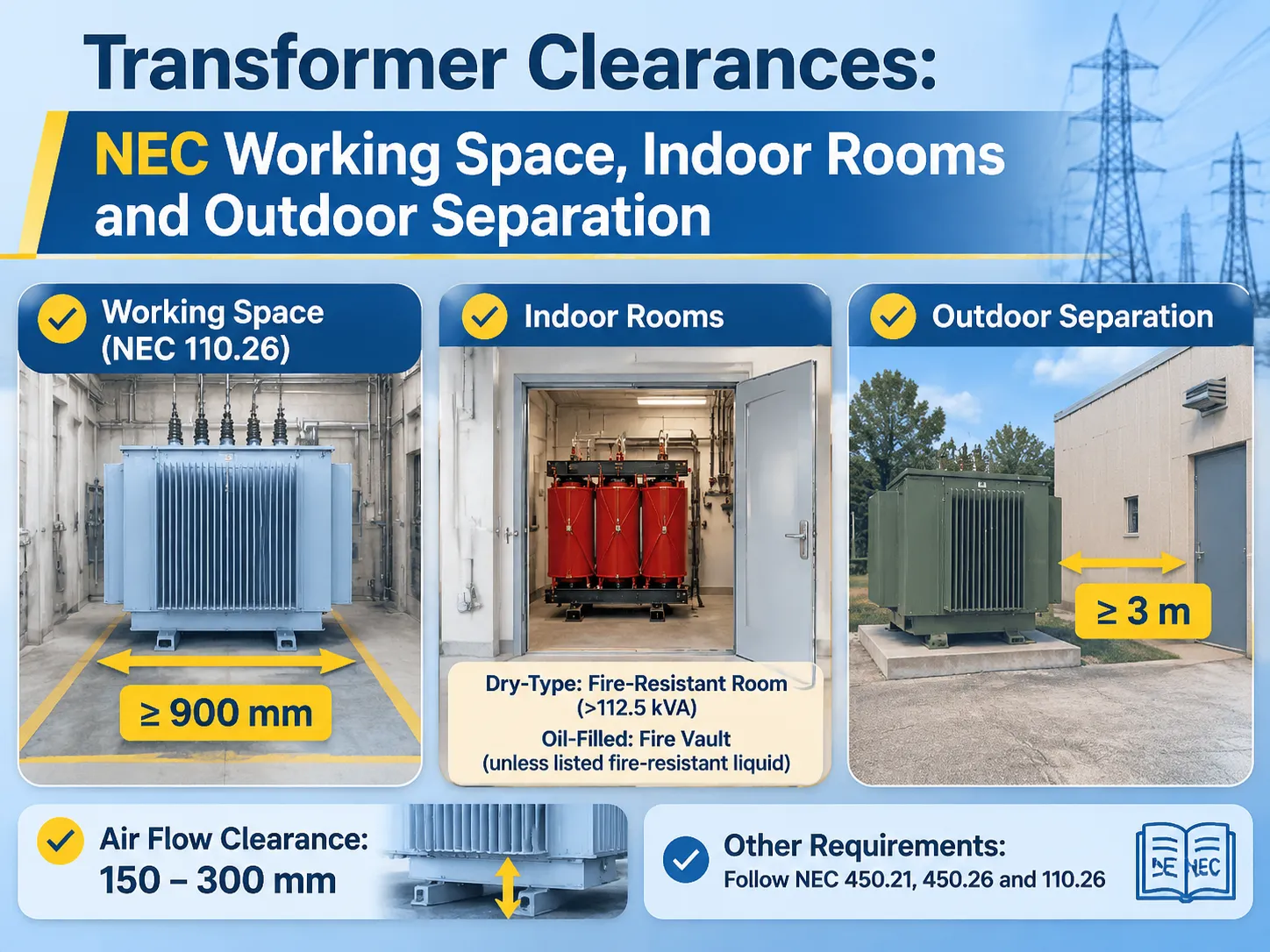
الأنواع الثلاثة للتباعد، ولماذا يتم الخلط بينها
هناك ثلاثة أنواع من التباعد وغالبًا ما يتم الخلط بينها.
، تجفيف مساحة العمل يتعلق الأمر بالأشخاص، وهو المساحة أمام المعدات التي يجب أن تبقى خالية لكي يتمكن شخص مؤهل من الوصول إليها، وأخذ قياس، والمغادرة. يتم تعريف مساحة العمل بناءً على الجهد الكهربائي الموجود على واجهة المعدات، وكذلك التيار المتدفق إلى المعدات. يمكن قياس كل هذا باستخدام أشرطة القياس ويجب أن يفي بالمواصفات أثناء الفحص.
عندما نشير إلى فواصل الحريق، فإننا نشير إلى المبنى. تشمل مسافات فواصل الحريق جميع المسافات/البُنى التي تفصل انتشار الحريق من المحول عن المواد القابلة للاشتعال أو من المحول إلى أي أسطح أخرى في الغرفة. تمثل مسافات فواصل الحريق إما بالمسافة بالمتر أو بتصنيف مقاومة الحريق للغرفة. في كلتا الحالتين، تعتمد على ما إذا كان المحول يحتوي على زيت.
تتعلق فواصل التهوية بشكل أساسي بالمعدات. يولد المحول الجاف حرارة بسبب الخسائر في لفائف المحول، وأي شيء يحجب تدفق الهواء البارد فوق لفائف المحول سيؤدي إلى زيادة درجة حرارة لفائف المحول، وتقليل عمر العزل، وفي النهاية إيقاف تشغيل المحول بواسطة الحماية الحرارية. يتم تحديد فواصل التهوية حصريًا من تعليمات تركيب الشركة المصنعة، والتي يتم ترميزها كمتطلبات يجب اتباعها، وغالبًا ما تحدد تخطيط الغرفة.
لذلك، بين مساحة العمل، وفواصل الحريق، وفواصل التهوية، يختلط الأمر على الناس لأنهم جميعًا يُطلق عليهم اسم "فاصل"، لكن واحدًا فقط موجود في جدول مرجعي للمركبين للرجوع إليه. وبالتالي، أي مكان إقامة يلبي متطلبات مساحة العمل (110.26) من الكود الكهربائي الوطني ولكنه غير مخطط وفقًا لفواصل التهوية، سيتم فحصه وتشغيله في بيئة تسبب ارتفاع درجة الحرارة. من ناحية أخرى، التخطيط الذي يلبي فواصل التهوية، ولكنه لا يلبي متطلبات مساحة العمل (110.26) سيتم فحصه والموافقة عليه مع وجود محول بارد.
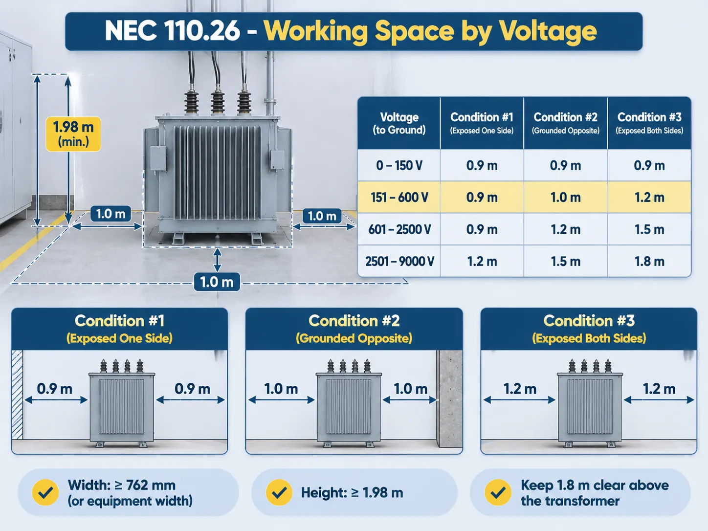
مساحة العمل بموجب NEC 110.26، حسب الجهد
يمكن حساب مساحة العمل، كما هو معرف في NEC 110.26، بناءً على حجم التركيب والمسافة من الموصلات الحية.
تختلف قياسات المسافة المطلوبة لكل جهد إلى الأرض ومتطلبات مساحة العمل بناءً على نوع الحاوية المعرفة في NEC: (1) الحالة #1 – أجزاء حية مكشوفة على جانب واحد ولا توجد حاويات حية أو مؤرضة على الجانب المقابل. (2) الحالة #2 – أجزاء حية مكشوفة على جانب واحد وأجزاء مؤرضة (مثل الخرسانة أو البناء) على الجانب المقابل. (3) الحالة #3 – أجزاء حية مكشوفة على كلا جانبي الحاوية.
| الجهد (إلى الأرض) | الحالة #1 | الحالة #2 | الحالة #3 |
|---|---|---|---|
| 0-150 فولت | 900 مم | 900 مم | 900 مم |
| 151 – 600 فولت | 900 مم | 0 م | 2 م |
| 601 – 2500 فولت | 900 مم | 2 م | 5 م |
| 2501 – 9000 فولت | 2 م | 5 م | 8 م |
معظم المحولات منخفضة الجهد، حوالي 151 إلى 600 فولت، تندرج تحت الحالة #2 مع عرض مساحة العمل الفعالة 1.0 متر بدلاً من العرض 900 مم المسموح به للحالة #1. يُعتبر الملف الابتدائي بجهد 480 فولت مع ملف ثانوي بجهد 208 فولت تركيبًا بجهد 480 فولت لأبعاد مساحة العمل. ينطبق متطلب الحالة #2 حيث يكون ظهر الكهربائي مقابل جدار من الطوب أو الخرسانة.
بالإضافة إلى متطلبات عرض وعمق مساحة العمل، تكمل ثلاثة أبعاد إضافية أبعاد مساحة العمل المحددة في NEC 110.26:
عرض مساحة العمل — مسافة دنيا 762 مم أو أكبر من عرض المعدات (أيهما أكبر). ارتفاع مساحة العمل — حد أدنى 1.98 م. يجب تخصيص مساحة العمل لمساحة العمل فقط؛ مما يعني أنه لا يجوز تركيب أو تثبيت أي شيء على المعدات ضمن نصف قطر 1.8 م. المتطلب الأخير هو الذي يمنع تركيب أي صينية كابلات مباشرة فوق المحول. يُرى هذا غالبًا في غرف المصانع حيث تم تحديد تخطيطات المصنع قبل تطبيق هذا القاعدة بشكل متسق.
ينطبق هذا المتطلب أيضًا على المحولات المغلقة بالكامل بسبب الحاجة إلى مساحة عمل للمعدات المثبتة بجانبها. بينما قد لا تحتوي الوحدة المغلقة بالكامل على أجزاء حية مكشوفة، لا تزال هناك أطراف تقع داخل حجرة يجب الوصول إليها أثناء التركيب والصيانة. يعترف الكود بالحاجة إلى مساحة عمل حول المحول بغض النظر عما إذا كان مغلقًا بالكامل أم لا.
النوع الجاف الداخلي: قاعدة الغرفة 450.21
يجب أن يكون أي محول جاف النوع يتجاوز 112.5 kVA ومثبتًا داخليًا داخل غرفة محولات يتم بناؤها وفقًا لمتطلبات البناء المقاوم للحريق ومعزولة عن بقية المبنى بواسطة جدران وأرضيات وأسقف ذات تصنيفات مقاومة للحريق محددة. المحولات التي تصنف أقل من 112.5 kVA لا تخضع لنفس متطلبات تصنيف مقاومة الحريق، ولهذا السبب توجد العديد من المحولات الصغيرة في خزائن وبالتالي لا تحتوي على حاوية مقاومة للحريق.
هناك استثناء محدد لهذا المتطلب ينطبق على مجموعة ضيقة جدًا من المشاريع. يُسمح بتركيب محول يحتوي على عزل من الفئة 155 أو أفضل ومفصول عن أي مواد قابلة للاشتعال بحاجز مقاوم للحريق خارج غرفة المحولات المخصصة. المفتاح هو أن يكون الحاجز المقاوم للحريق مبنيًا كجدار صلب على جميع الجوانب الأربعة للمحول يفصله عن المواد القابلة للاشتعال.
من المهم فهم تصنيف العتبة كاعتبار تصميمي عند تركيب محول داخلي أو خارجي.
يُعتبر حجم 112.5 KVA محولًا تجاريًا صغيرًا، والمستوى التالي، 150 KVA، لن يتطلب فقط كابلًا أكبر بل أيضًا غرفة أكبر لاستيعابه. يمكن أن تُسبب المحولات المصممة خلال المراحل الأخيرة من البناء تعقيدات. على سبيل المثال، إذا قام المقاول بتغيير التصميم من محول 112.5 KVA إلى 150 KVA، فقد يحتاج إلى إضافة مساحة إضافية لذلك المحول أثناء البناء.
عند تصميم المساحات للمحولات التي تستخدم راتنجات مصبوبة ولديها نظام تبريد، ستحدد متطلبات نظام التبريد التخطيط النهائي لغرفة المحول. لكي تتمتع محولات الراتنج المصبوب بتهوية كافية، فإنها تتطلب مسافة خلوص إضافية تتراوح بين 150 مم إلى 300 مم من كل جانب من المحول. علاوة على ذلك، يجب أن تحتوي غرف المحولات على فتحات مجاري دخول وخروج بحجم مناسب للحمل الحراري الكلي، وليس لكل محول على حدة. استفساراتنا التجارية المتعلقة بمحولات النوع الجاف الداخلية تقريبًا تستند حصريًا إلى محول 10 kV من سلسلة SCBH. يمكن العثور على متطلبات التركيب لمحولات SCBH في المستندات المقدمة. تشمل متطلبات الخلوص لكل وجه من المحول ضمن المستندات المقدمة، لذلك لا حاجة للمقاول للتخمين أو الافتراض بشأن متطلبات الخلوص.
المحولات المملوءة بالزيت داخل المباني: الخزانات والاستثناء الأقل قابلية للاشتعال
سيتطلب تركيب محول معزول بالزيت داخل المبنى أن يتم تركيبه في خزانة زيت. يجب أن تلبي الخزانة معايير إضافية، مثل مقاومة الحريق واحتواء السوائل، والتصريف، والتهوية، لتلبية غرضها. في حالة المحول المعزول بالزيت، تكمن المخاوف المتعلقة بخطر الحريق في إمكانية إنتاج كمية كبيرة من الغاز الساخن التي يمكن أن ينتجها المحول نفسه بالإضافة إلى تسرب الزيت الذي قد يحدث إذا فشل المحول الزيت.
تغيير إضافي في سوق المحولات يرجع إلى توفر سائل أقل قابلية للاشتعال.
يسمح NEC 450.23 بتركيب داخلي لمحول يحتوي على سائل غير قابل للاشتعال من خلال طريقة مدرجة طالما أن هناك مسافة دنيا من المواد القابلة للاشتعال وفي الوحدات الأكبر وجود حماية حريق تلقائية كافية. تم استخدام هذه السوائل القائمة على الإستر، سواء الطبيعية أو الصناعية، إلى حد كبير في المشاريع في السنوات الأخيرة؛ وبالتالي، أصبح استخدام وحدة مملوءة بالزيت داخلية معيارًا وليس تخصصًا.
هناك أربعة شروط يجب تلبيتها للتأهل لهذا الاستثناء للسائل: (أ) يجب أن يكون مدرجًا كأقل قابلية للاشتعال، (ب) يجب أن تكون الشهادة المدرجة محددة لذلك السائل وليس لعائلة السوائل، و(ج) يجب أن يكون هناك فصل، عادة مسافة 3 أمتار من المواد القابلة للاشتعال أو حاجز مقاوم للحريق، (د) يجب أن يكون مستوى الحماية من الحريق وفقًا لما تتطلبه القائمة عند ذلك التصنيف؛ بالنسبة للمحولات الصغيرة لا يُطلب شيء، ولكن بالنسبة للمحولات الكبيرة سيُطلب نظام إخماد.
بشكل عام، تتطلب المشاريع التي تستخدم الزيت المعدني وجود غرفة محمية، ويجب أيضًا تصميم تهوية الغرفة المحمية. يجب أن تحتوي الغرفة المحمية على مدخل ومخرج بحجم مناسب لفقدان الحرارة، بالإضافة إلى حماية كافية ضد الأمطار ودخول الحيوانات. إذا كان المشروع يقع في مناخ حار، فإن درجة الحرارة داخل الغرفة المحمية ستحد من تصنيف المحول في مرحلة ما؛ لذلك، من الجدير ذكر ذلك للمهندس المعماري في أقرب وقت ممكن. The 20 kV oil immersed distribution transformer is the most common transformer discussed when discussing this subject with the architect and including the specifications of the transformer fluid as part of our proposal is imperative.
Outdoor Separation: The 3 m Rule and Fire Barriers
Protecting the area around the transformer with a sufficient distance from combustible materials outside of buildings provides a reasonable amount of fire separation.
Distance is measured from the boundaries of the transformer enclosure, but the distance remains regardless of the position of any combustible materials near the building. A pad mounted permanently on or over a combustible architectural element is a violation unless that architectural element has been classified as either a fire barrier or has an acceptable fire rating.
The location of the transformer enclosure will affect the layout of the transformer site on an overall site basis.
Three other elements that relate to the distance between the transformer enclosure and the nearest point of combustible construction are:
- The bund or plinth must direct any liquid spill from the transformer enclosure away from the nearest building and away from any storm drain.
- Access must be maintained to allow installation, maintenance, or replacement of the enclosure.
- Security requirements to secure the enclosure against unauthorized entry into public areas require that the enclosure have a locking device that can be opened by the utility.
، تجفيف pad-mounted transformer enclosure is where the intersection of the above listed elements meets. This may explain why pad-mounted transformers have set back requirements, while substations constructed off-site in a prefabricated unit are considered as separate buildings requiring their own set of fire strategies.
The Air Circulation and Ventilation Requirements Indicated by the Manufacturer
The air circulation is the primary method of cooling a dry-type transformer, which is common in commercial environments. Since dry-type transformers depend on moving air to cool them, the evaporating surfaces are always located completely exposed with no obstructions. The ventilation face surfaces must maintain a minimum clearance of between 150-300 mm (6-12 inches) from any obstructing objects; if the dry-type transformer has a higher rated capacity (greater than 1000 kVA) or has been installed with an acoustic enclosure, the clearances must be even greater than the 150-300 mm (6-12 inches) recommended.
When looking at the ventilation and cooling of a dry-type transformer, it is important to look at not only the transformer, but also the room that houses it. Dry-type transformers can reject many kilowatts (kW) of heat. If the transformer is in a completely sealed enclosure, the ambient temperature in the room will ultimately be at a level where the transformer will derate. Therefore, it is extremely important that when designing a room, that the appropriate amount of inlet and outlet area is calculated for the transformer rating being installed; a room designed for a 500 kVA transformer cannot have a 1000 kVA transformer installed in it without proper ventilation and cooling capabilities.
Sound is also another important factor in the design of a dry-type transformer installation. If a transformer is located very close to a solid wall, the sound from the transformer will reflect off the wall and cause an increase in perceived sound levels; this can cause complaints in a manufacturing environment. Therefore, moving a transformer at least 300 mm (12 inches) away from the wall at the design phase is cost-effective, but making this change at a later date can be very costly.
Accessibility, Disconnection and Dedicated Space
The three basic features of dry-type transformer design, aside from dimensions, are very often overlooked: access to qualified personnel; how to safely and effectively disconnect the transformer; and the amount of dedicated space required. Although a dry-type transformer must be accessible to qualified personnel, installing the transformer above a ceiling is only acceptable if the qualified personnel can access the transformer without having to remove the building finish.
To ensure a safe work environment for electricians, there must be a disconnection device located within sight of the electrical equipment. If it cannot be seen, then it must have a way to prevent it from being re-energized (that is, a lockable device). In addition, working space requirements are specific and must be maintained; therefore, no items such as ladders, boxes, spare pumps, etc., should be placed in front of the equipment that requires a dedicated work area.
The accessibility requirement has application to dry-type transformers. The Canadian Electric Code (CEC) has issued the following: Where a dry-type transformer is installed in a ceiling void and can be accessed via an access panel, and the transformer has a rating below the established limit, the CEC allows an approved small transformer. However, if a transformer requires a ladder for installation and/or requires removal of ceiling tile as part of the installation process, it is considered a maintenance issue rather than an approved installation.
Canada: CEC Rule 2-308 and Where It Differs
Canada is also governed by the Canadian Electrical Code (CEC), Section 2-308 2, and Rule 2-308 identifies the requirements for working space surrounding electrical equipment. The working space surrounding electrical equipment must have a minimum height of 2 meters, a width that is equal to the size of the electrical equipment; or 750mm; and a depth that is at least 1 meter in front of the equipment. The numbers stated above agree with the NEC numbers, but the structure is different; CEC has one working space number “1 meter” rather than use a table similar to the NEC to categorize working space by the voltage and condition; therefore the Canadian requirements are simpler to use and slightly more restrictive at low voltages.
Transformers are covered in Section 26 of the Canadian Electrical Code. The fire separation of the transformers is similar to the fire separation for other electrical equipment; the fire separation of dry-type transformers above a certain rating require the dry-type transformer to be installed in a fire-rated room or a fire-separation location; likewise, oil-filled transformers must be installed in vaults and have their own fire separation from combustible construction if installed outdoors.
Each province has its own amendments. Therefore, some projects will be subjected to more demanding standards/requirements from local jurisdictions in provinces/states than the model code.
For projects that cross the province/state line, the practical approach is to design for the most stringent of the two forms and keep a record of which one you used to create your project. The layouts meeting both sets of requirements are seldom costlier than those meeting only the NEC, since the only difference in the depths between the two is typically 100 mm.
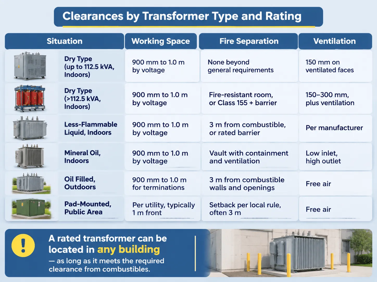
Clearances by Transformer Type and Rating
The information contained in the table is a summation of the information that appears on the drawings, and it is not intended to substitute for the text of the code if your project has local amendments, you still are held to the local provisions.
Type of transformer and location. Range of ratings and sizes of rated transformers will differ due to use. Fire resistance is a function of building design.
| الحالة | Working space | Fire separation | التهوية |
|---|---|---|---|
| Dry type up to 112.5 kVA, indoors | 900 mm to 1.0 m by voltage | None beyond general building requirements | 150 mm on ventilated faces |
| Dry type above 112.5 kVA, indoors | 900 mm to 1.0 m by voltage | Fire-resistant room, or Class 155 plus barrier | 150 to 300 mm, plus room ventilation |
| Less-flammable liquid, indoors | 900 mm to 1.0 m by voltage | 3 m from combustible, or rated barrier | Per manufacturer, room ventilation required |
| Mineral oil, indoors | 900 mm to 1.0 m by voltage | Vault with containment and ventilation | Low inlet, high outlet, sized for losses |
| Oil filled, outdoors | 900 mm to 1.0 m for terminations | 3 m from combustible walls and openings | Free air, clear of screens and vegetation |
| Pad-mounted, public area | Per utility, typically 1 m front | Setback per local rule, often 3 m | Free air, clear of snow accumulation |
As you can see in the second column, rated transformers can be located in any building as long as they meet the required distance from combustibles.
- A rated transformer may be less than or equal to the fire rating.
- A rated transformer is one that has been tested under the manufacturer’s guidelines.
- Manufacturer recommendations for rated dry-type transformers should only be used as a guideline.
- The distance from combustibles for a rated transformer is only one consideration.
- Fire resistance is a function of the building’s design and cannot be used to determine the fire protection level of a rated transformer.
- A higher fire rating does not guarantee that the transformer will provide a higher level of protection than a lower fire-rated transformer.
What a Layout Drawing Has to Show
Five different dimensions are required to be on the drawing. If any of these five dimensions are missing, the drawing will be rejected. The working space in front of the unit has to be shown, along with the voltage and condition that created the working space width in front of the equipment. You will need to show the working space width, with a minimum of 762 mm or the width of the equipment, whichever is greater. The distance to the nearest combustible material or the fire rating of the partition or wall at a barrier must be included as well. The ventilation clearance from each ventilated face of the unit must be shown. You will also need to include the door swing of the unit. If the door opens into the working space, you will not have a working space.
Two other things are best to include to avoid arguments in the future. The cable entry/exit and bending radius; a transformer with a 300 mm space from the wall and a 400 mm cable bend radius would not work. The path for lifting the unit into place; a unit that has to be craned in through a roof opening must have the opening sized prior to erecting the wall.
For a substation package, the typical distribution substation equipment dimensions and clearances are given as part of the enclosure dimensions. The site dimension outside the enclosure is the second part of the drawing and is built by the civil contractor.
Where SUBIAN Fits
We manufacture the transformers that provide these types of clearance in dry or oil-immersed configurations and range from distribution transformers with 100–200kVA up to transformer stations with approximately 5MVA. We only assist in providing the installation information for clearance purposes. Installation information includes transformer heat losses at each rating; ventilation requirements by face; enclosure dimensions (length x width x height); and weight, allowing the facility owner/installer to size the installation prior to shipping.
We cannot provide advice concerning fire protection strategies, i.e., whether a room requires a one-hour rating, whether a vault must be used, or whether a less combustible fluid can be used as an acceptable fluid by the Authority Having Jurisdiction (AHJ). These are questions for the building designer and local AHJ inspectors. Providing answers based on drawings without seeing the actual facility is purely speculative and can be costly if the guess is incorrect.
Where we excel is at the point where the transformer dictates the four elements we require at the request for quotation stage before the transformer will change the room’s design; these include fluid type, enclosure dimensionality, heat losses, and weight. A transformer’s rated voltage ratio and altitude are also important.
الأسئلة المتكررة
How much clearance is required for a 480V panel?
The minimum clearance for a 480V panel according to Condition 1 (live part(s) on one side with no live or grounded part(s) on the opposite side) is at least three feet or 900 millimetres of clearance. The depth of the wall behind the electrician is 1.0 m where it is masonry and 1.2 m where there are electrical appliances on either side. The width must be 762 mm, the width of the equipment, and the height must be 1.98 m.
What is the 80% transformer rule?
It is an industry rule of thumb, not a rule of code, that the transformer be planned for a permanent maximum of approximately 80% of the rating because operating it at above that rating will shorten insulation life and leave no allowance for the load to increase. The code’s equivalent is that the over-current protection and continuous load sizing be at 125%, giving an equivalent buffer in the opposite direction.
What is the clearance requirement between a transformer and a building?
The typical distance between an oil-filled unit and combustible materials outdoors is 3 m or, in lieu of a fire barrier or rated wall, some other distance. The indoor requirement for dry-type equipment is that a room must be fire-resistant for transformers rated at 112.5 kVA or larger; there is no distance requirement. There is a middle ground with units that use Less Flammable Liquids, which must be located 3 m or (if there is a rated barrier) from combustible materials.
What are CEC clearance requirements for transformers?
Rule 2-308 requires that all electrical apparatus be located within a 1 m area with a minimum of 2 m of headroom and a width equal to the electrical apparatus or 750 mm. Rule 26 details the fire separation and vaulting requirements for transformers, and the provincial government may have more stringent regulations than the model code.
Do dry-type transformers require a fire-rated room?
Fire-rated rooms are only required for dry-type transformers rated above 112.5 kVA installed indoors, unless the unit has Class 155 insulation that is separated from combustibles by a fire-resistant barrier. A lower-rated transformer does not need to be installed in a fire-rated room, although such barrier requirements may still exist under the Building Code for other reasons.
Can a transformer be installed in a ceiling space?
Yes, but only for small dry-type transformers in ceilings that qualified personnel can access without removing building materials and can maintain clear working space. Practically speaking, this means sufficient headroom and an access panel, making this one of the most commonly failed installations for retrofits.
المراجع
- NFPA — National Electrical Code Articles 110 and 450
- Siemens Energy — Transformer Installation and Room Design
- Hitachi Energy — Distribution Transformer Application Data
- SGB-SMIT Group — Dry-Type and Liquid Filled Transformers
- Electrical Engineering Portal — Substation and Plant Room Layout
Summary
Three clearances (working space, building fire separation, and ventilation clearance) are associated with transformers (working space is for the individual, building fire separation is for the facility that houses the transformer, and ventilation clearance is to keep the winding temperature down). A layout that optimally accommodates all three clearances is compliant and cool, whereas layouts that accommodate only two will typically be found either “fail” inspections or spark a unit overheating situation.
Throw-in numbers for design review are 1.0 m in front and 112.5 kVA to be room threshold. 3 m for oil transformer outdoors and all of the rest of the clearances are found in the code with inspectors having the code in front of them when conducting the inspections.