


Im Wesentlichen ist ein Hochspannungstransformator ein Gerät, das verwendet wird, um die Spannung von einer eingehenden Leitung auf ein Niveau zu erhöhen, das für die weitere Übertragung elektrischer Energie erforderlich ist. Diese Definition umfasst jedoch auch Überspannung, d.h. eine abnormale Situation, in der die Ausgangsspannung die Nennspannung aufgrund unsachgemäßer Abgriffänderungen oder Lockerung des Neutralleiters des Stromsystems überschreitet. Obwohl im Absatz zwei Situationen beschrieben werden, ist ihre Natur ganz unterschiedlich, und dies kann einen Techniker zu einer falschen Lösung des Problems führen, wie z.B. das Einstellen eines Abgriffwechslers, wenn ein offener Neutralleiter die eigentliche Ursache ist. Ziel dieses Handbuchs ist es, ein umfassendes Verständnis dafür zu vermitteln, wie ein Transformator als Spannungsanhebungseinrichtung funktioniert, was mit dem elektrischen Strom und der elektrischen Last passiert, während die Spannung der Leitung erhöht wird, und welche Auswirkungen dies zur Folge hat.
Kurz gesagt: Wenn ein Transformator die Spannung erhöht, wird die Spannung auf der Sekundärseite höher als die Spannung auf der Primärseite gemäß dem Verhältnis der Windungszahlen — Vs/Vp = Ns/Np — während der Strom im gleichen Verhältnis sinkt. Dies liegt daran, dass der Transformator Leistung überträgt, aber keine Leistung erzeugt. Dieser Aspekt ist die erste und wichtigste Konsequenz der Transformatoren. Nach dieser ersten Konsequenz gibt es vier weitere Konsequenzen. Die Isolierung muss erhöhten dielektrischen Spannungen standhalten, was bedeutet, dass die Wicklung, die bei höherer Spannung arbeitet, eine bessere Isolierung haben muss. Widerstandsgeräte erhalten mehr Energie, da das Quadrat der Spannung wächst, was bedeutet, dass, wenn die Spannung um 5% steigt, die Erwärmung in Widerstandsgeräten um fast 10% steigt. Eine Glühlampe hört auf zu leuchten, wenn die Spannung das zulässige Spannungsniveau überschreitet. Der Kerninduktor sättigt, wenn die Spannung weit über den Entwurfsbereich hinausgeht.
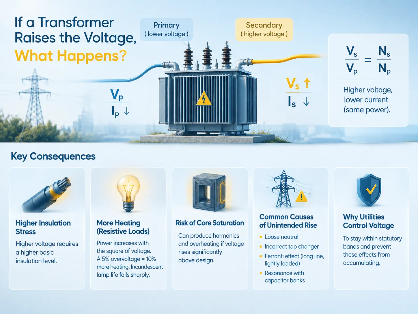
Wie ein Transformator die Spannung erhöht
Transformatoren sind Geräte, die vollständig aus stationären Komponenten bestehen und keine elektrische Verbindung zwischen ihren Wicklungen haben. Sie arbeiten durch elektromagnetische Induktion; mit anderen Worten, in der Primärwicklung fließt ein Wechselstrom, und daher ein sich änderndes Magnetfeld; dieses sich ändernde Magnetfeld erzeugt dann eine Spannung in der Sekundärwicklung. Die erzeugte Spannung entspricht der Primärspannung multipliziert mit dem Verhältnis der Sekundär- und Primärwicklungen.
Die Spannung, die in der Sekundärwicklung eines Transformators erzeugt wird, hängt vom Verhältnis der Windungen seiner Drähte zu den Windungen der Primärwicklung ab. Wenn beispielsweise die Windungen in der Sekundärwicklung doppelt so viele sind wie in der Primärwicklung, ist es richtig zu sagen, dass die Spannung in der Sekundärspule auch doppelt so hoch ist wie die Spannung in der Primärspule. Es ist dieses Verhältnis zwischen dem Windungsverhältnis, das einem Transformator die Fähigkeit verleiht, die Spannung zu erhöhen oder zu senken, und das die Vorteile erklärt, die solche Transformatoren mit sich bringen, einschließlich ihrer Verwendung in umgekehrter Weise.
Die einzige Einschränkung der Größe und Kapazität eines Transformators wird durch das Kern-Design bestimmt. Die magnetische Flussdichte im Kern wächst proportional zur angelegten Spannung an der Spule. Daher gilt: Je höher die Spannung, desto gesättigter wird der Kern. Wenn der Kern den Sättigungspunkt erreicht, kann die Flusslinie nicht mehr hindurchfließen. Das Verständnis der grundlegenden Konstruktion, die diese Grenzen erzeugt, ist der Ausgangspunkt, und es wird in unserem Leitfaden dargelegt. Grundlagen der Verteilungstransformatoren.
Wo das Verhältnis bei der Herstellung festgelegt ist, ist der Parameter, der die tatsächliche Ausgangsspannung bestimmt, die Anzahl der Windungen im Stromkreis an der angezapften Wicklung – der Grund, warum Abgriffwechselrichter existieren. Diese Einstellungen und die restlichen Daten auf dem Typenschild sind Gegenstand unserer Erklärung zu Transformator-Spezifikationen, wo ein Käufer nachsehen sollte, bevor er annimmt, dass ein Spannungsproblem ein Fehler ist.
Die Erhaltungsregel: Spannung hoch, Strom niedrig
Das bedeutendste Ergebnis der Erhöhung der Spannung wird oft übersehen: Der Strom sinkt.
Ein idealer Transformator überträgt Energie ohne Verlust, und daher muss der Wert der Spannung multipliziert mit dem Strom auf beiden Seiten identisch sein. Wenn die Spannung an der Sekundärseite steigt, sinkt der Sekundärstrom, der bei gleichem Strom an der Primärseite fließt, entsprechend. Mit anderen Worten, wenn ein Transformator einen Strom von 100 A bei 240 V auf der Sekundärseite liefert, während er 200 A bei 120 V auf seiner Primärseite verbraucht, ist die Leistung auf beiden Seiten gleich, da kein neuer Strom erzeugt wird.
| Menge | Beziehung | Konsequenz der Erhöhung der Sekundärspannung |
|---|---|---|
| Spannung | Vs/Vp = Ns/Np | Steigt proportional zum Windungsverhältnis |
| Strom | Is/Ip = Np/Ns | Fällt umgekehrt proportional |
| Leistung | VpIp ≈ VsIs | Unverändert, abgesehen von Verlusten |
| Impedanz, die von der Quelle gesehen wird | Zp = (Np/Ns)² × Zs | Transformiert durch das Quadrat des Windungsverhältnisses |
Die Impedanzreihe ist wichtig zu berücksichtigen, da sie die am wenigsten intuitive ist. Eine Last an der Sekundärseite wird von der Quelle nicht als sie selbst, sondern multipliziert mit dem Quadrat des Windungsverhältnisses gesehen. Bei einer zehnfachen Erhöhung der Spannung sieht eine 1Ω-Last aus der Primärseite wie 0,01Ω aus. So erfolgt die Impedanzanpassung in Audio- und RF-Schaltungen, und genau das ist der Grund für das Phänomen eines Hochspannungstransformators, bei dem eine gewisse Menge an fester Last viel höheren Primärstrom zieht, als man aus einfachen Berechnungen erwarten würde.
Im wirklichen Leben erreicht ein echter Transformator keine 100%-Erhaltung. Sowohl Kupferverluste in den Wicklungen als auch Kernverluste im Kernmaterial dissipieren in Form von Wärme, weshalb die Effizienz in Prozent ausgedrückt wird, anstatt als eins angenommen zu werden, und der Grund, warum Transformatoren unter Last warm werden, während sie im offenen Stromkreis kühl bleiben. Die Verluste selbst gehören zu den Mechanismen, die letztendlich die Lebensdauer eines Transformators begrenzen, ein Thema, das in unserem Artikel über was Transformatoren zum Ausfall bringt.
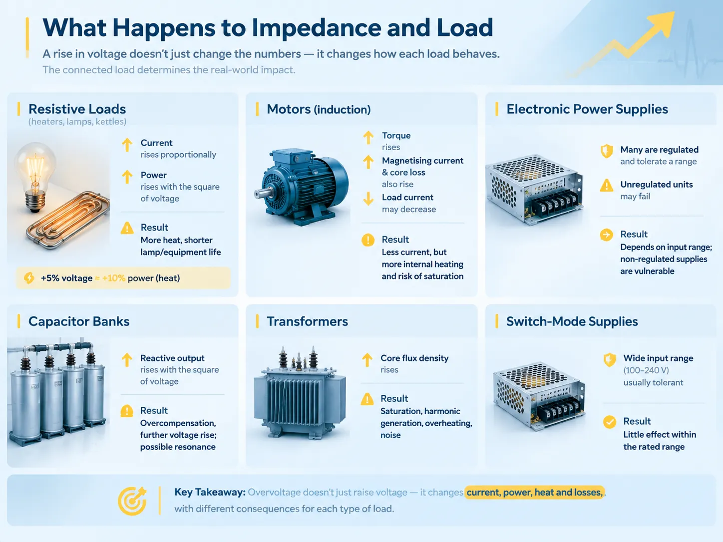
Was mit Impedanz und Last passiert
Die Art der angeschlossenen Last bestimmt vollständig, wie die angeschlossene Last reagiert, und somit wird das Ergebnis des Anstiegs der Spannung von einer Entwurfsspezifikation zu einer betrieblichen Angelegenheit.
| Lasttyp | Verhalten bei Spannungsanstieg | Ergebnis |
|---|---|---|
| Widerstand (Heizgeräte, Glühlampen, Wasserkocher) | Der Strom steigt proportional; die Leistung steigt mit dem Quadrat der Spannung | Erhöhte Erwärmung; die Lebensdauer der Lampe sinkt drastisch |
| Motoren (Induktionsmotoren) | Das Drehmoment steigt, aber auch der Magnetisierungsstrom und der Kernverlust; der Motor kann bei Strom kühler, aber im Kern heißer laufen | Reduzierter Stromverbrauch, aber erhöhte magnetische Verluste; Überhitzung, wenn die Spannung deutlich über dem Nennwert liegt |
| Elektronische Stromversorgungen | Viele sind geregelt und tolerieren einen Bereich; diejenigen, die es nicht sind, können ausfallen | Hängt vollständig vom Eingangsbereich ab; ungeregelte Versorgungen sind anfällig |
| Kondensatorbänke | Reaktive Leistung steigt mit dem Quadrat der Spannung | Überkompensation und weiterer Spannungsanstieg; mögliche Resonanz |
| Transformatoren | Die Flussdichte im Kern steigt; Sättigung und harmonische Erzeugung über dem Entwurfspunkt | Überhitzung, harmonische Verzerrung, hörbare Geräusche |
| Elektronik mit Schaltnetzteilen | In der Regel breiter Eingangsbereich (100-240 V), daher tolerant | Geringe Auswirkungen innerhalb des Nennbereichs |
Die Widerstandsreihe enthält eine interessante Beobachtung. Bei Widerstandsbelastung steht die Leistung im Verhältnis zum Quadrat der Spannung. Daher entspricht jede Überspannung wie 5% etwa 10% mehr erzeugter Wärme. Im Falle eines Heizelements bedeutet dies eine viel kürzere Lebensdauer des Elements sowie höhere Energiekosten. Bei Glühlampen bedeutet dies jedoch eine noch kürzere Lebensdauer aufgrund der starken Abhängigkeit der Lebensdauer von der Überspannung. Dies ist auch der Grund für die Bedeutung der Spannungsregelung für Versorgungsunternehmen, da es für die Nutzer echte, messbare und steigende Kosten aufgrund von Überspannung gibt.
Die Motorreihe ist subtiler, als es auf den ersten Blick scheint. Wenn der Motor mehr Spannung erhält, verbraucht er bei gleichem mechanischen Output weniger Strom, was zunächst gut aussieht, aber in Bezug auf den magnetischen Kreis ist die Situation ganz anders. Der Grund ist, dass die erhöhte Spannung den Kernverlust steigen lässt, der Motor intern überhitzt, trotz des Rückgangs des Stroms, und bei sehr hoher Spannung beginnt die Sättigung des Eisens.
The Physical Effects of Higher Voltage
In addition to the effect(s) on the load, increases in voltage also put stress on the transformer in four ways.
- Stress on insulation. Insulation stress increases with increased voltage, and as insulation stress increases, lifetime of the insulation decreases. As a consequence, a transformer with a higher winding voltage must also have a higher basic insulation level; also, for the same reason, lightning impulse withstand voltage becomes one of the items in the specification and not a detail.
- Partial discharge. When stress is high enough, a void or defect within the insulation may start discharging, which leads to gradual deterioration of that material. Partial discharge serves as a precursor of a failure but it is not a failure itself, and it is one of the side effects of overvoltage.
- Core saturation and harmonics. When a core is driven above its design magnetic flux density (material and configuration of the core determine the level of the magnetic flux that the core can withstand), the magnetizing current becomes distorted and starts containing some odd harmonics that result in increased losses, increased temperature, and may result in resonances somewhere else in the system.
- Increased audible noise. Magnetostriction–the dimensional change of the core due to the magnetization–also increases with increased flux density; thus, an overvoltage transformer produces significantly more audible sound than the same transformer at normal voltage levels.
These four phenomena have the common feature that makes overvoltage dangerous: they are cumulative and pretty much invisible. It happens so that an overvoltage transformer does not give any signs of trouble, it just ages more quickly, and failure happens sooner than expected.
Unintended Voltage Rise: The Causes
There are four chief reasons why voltage levels will be excessive other than being deliberately raised.
| Ursache | Mechanismus | How to recognise it | Response |
|---|---|---|---|
| Incorrect tap changer setting | The tap is set for a different supply voltage than the one present | Consistent, predictable offset across all loads; present at all times | Reset the tap to match the actual supply; verify with a measurement |
| Lost neutral | The neutral reference floats, so voltage divides between legs by load impedance | Voltages on two legs sum to the full line voltage; some loads see high voltage while others see low | Emergency: isolate and treat as a supply fault |
| Ferranti effect | On a long, lightly loaded line the capacitive charging current raises the receiving-end voltage above the sending-end voltage | Voltage rises as load falls; worst at night or in low-demand periods | Reactive compensation, or accept it if within limits |
| Capacitor bank resonance | Power factor correction capacitors resonate with system inductance, amplifying voltage at a harmonic frequency | Distortion and voltage rise correlated with capacitor switching | Detune or retune the bank; investigate harmonics |
| PV or generation backfeed | Embedded generation raises voltage at the point of connection when exporting | Voltage rises when generation is high and local load is low | Transformer tap adjustment, voltage regulation, or export limitation |
The simplest cause is a faulty tap changer. If the tap changer is set incorrectly, the transformer will supply the expected voltage all the time, and the solution would entail resetting it correctly after finding out the true input voltage instead of using the nominal voltage value. In the context of tap changers, there exist off-circuit (can be set only when the transformer is not energized) and on-load tap changers that can allow to perform their operation under load and typically function in accordance with a volt-regulating relay.
The Ferranti effect is another cause that presents a surprise. It is based on the fact that a long-way transmission or power supply line has capacitance distributed along its length, and when the very line is not loaded much, the capacitive current traveling through the inductance of the line will cause the voltage to increase instead of decreasing. The nature of the effect is proportional to the line length and inversely proportional to load capacity meaning that the effect is the most severe in case of long lines and low loads that is why a voltage drop problem can happen at night rather than when consumption is higher.
The Lost Neutral Case
This missed depth is the reason why there may not be general distinctions between this cause and other such reasons, as the answer is different in nature, viz. a crisis rather than an adjustment.
In the case of a split-phase supply, the centre tap of the transformer provides the neutral, which keeps both the line-to-neutral voltages at their normal levels. If the neutral connection is loose, corroded, or open at any point, such as at the transformer, in the service drop, at the weatherhead, at the meter base, or in the panel, the reference is lost. The two line conductors plus the loads connected between them and the neutral are in series for the whole line voltage, and the voltage is distributed depending on the impedances of the loads on either side.
The resulting effect is that a voltage rises on one side and falls on the other side. Thus, loads in the lightly loaded leg will take voltages almost equal to the full line voltage, whereas devices on the heavily loaded leg will note nearly no voltage changes. The voltage differences are due to the nature of the electrical appliances, since whenever any electric device is switched on, the balance is altered. The key symptom is burnt devices on one side and underperforming devices on its opposite side in parallel.
This is why a lost neutral should be viewed as an emergency of the supply and not as a regulation issue.The protective arrangements that limit damage in such events, and the role of the neutral in the grounding scheme, are covered in our guide to Grundlagen der Transformator-Erdung.
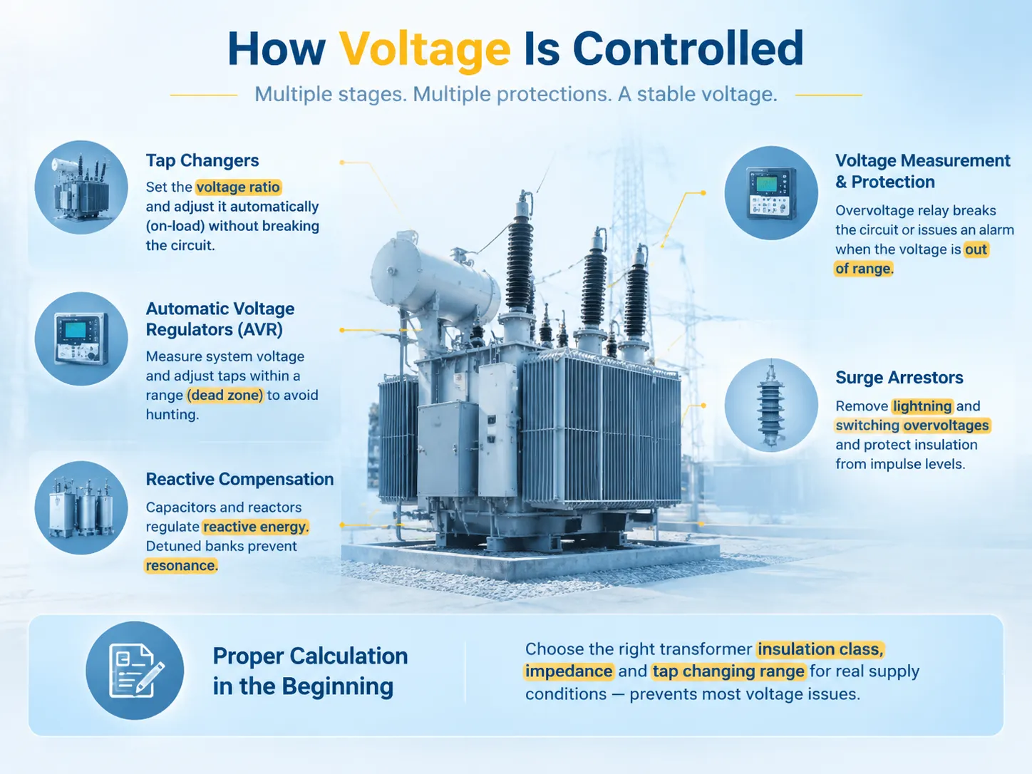
How Voltage Is Controlled
Voltage control is integrated into the system at multiple stages as both the expected and unexpected voltage variations are important.
- Tap changers. Off-circuit tappers set the voltage ratio and on-load tap changers change the ratio without breaking the electrical circuit under the supervision of the automatic voltage regulator.
- Automatic voltage regulators and compensators. They measure the voltage in the system and change tap to maintain the voltage in the range with dead zone to avoid hunting.
- Reactive compensation. Capacitors and reactors regulate the reactive energy which causes voltage variation due to load, detuned battery eliminates the resonance issue.
- Voltage measurements and protection. The overvoltage relay breaks the circuit or indicates the occurrence of the voltage level outside the acceptable range—last opportunity for voltage protection.
- Surge arrestors. They eliminate overvoltage coming from lightning and switching action and do not allow the insulation to operate beyond its impulse level.
- Proper calculation in the beginning. Choosing the transformer of the needed insulation class and impedance as well as the tap changing range for real supply conditions prevents most of the issues described in this article because this is the reason why the specification is the most important step.
For a site installing or replacing a distribution transformer, the practical step is to specify against the measured supply voltage and the expected load profile rather than against nominal figures. Our Verteiltransformatorbereich illustrates the parameters that should be pinned down — rated voltages, tap range, impedance, insulation level and cooling class — because each of them determines how the unit behaves when the supply is not exactly nominal.
Voltage Limits and Standards
Utilities don’t attempt to keep voltage consistent; instead, they keep it within a band and the extent of that band defines what kind of variations equipment can withstand.
In North America, the main specification used is ANSI C84.1, which specifies for example the so-called Range A utilities (roughly ±5% of nominal) as a range within which equipment is expected to work and which is referred to as Range B or (approximately ±5.5%) range that is expected to be tolerated but not sustained. If we take 120 V service we get roughly 114-126 V for Range A and if we take 240 V services we get roughly 228-252 V.
In Europe, EN 50160 specifies the voltage characteristics of voltage in use and which states nominal voltage of 230 V and allowed variations in the surrounding space about ±10% during most of the time and also with the restrictions on harmonics, flicker and unbalance. Able equipment in the circuits designed for the European market will be able to work with these band characteristics of the voltage.
Practically this means that nominal voltage is probably a more exactly defined mean of the voltage which is required from the transformer. The transformer should be chosen in such a way that it provides correct voltage (nominal voltage) at some point in the band of available supply voltage and for the insulation to work normally at the top level of this band and for the load to be compatible with calculating this variation. In case something is happening in the supply and if some company’s supply has always been near a band edge, it would be better to adjust tap.
FAQ
How does a transformer increase the voltage?
Utilizing electromagnetic induction and turns ratio for an electric transformer. It generates a magnetic field in the magnetic core through the process of inducing current. In case the secondary winding of the transformer has more turns than the primary winding, the voltage induced is proportionately high, meaning that the ratio Vs/Vp = Ns/Np applies. There is no logical connection between the branches and energy is not produced and thus the transformer performs the transfer of electrical power in a different circuit with an alteration of voltage – current ratio at the same time.
What would cause a transformer to have high voltage?
There are four main reasons. A tap changer that is incorrectly adjusted will give rise to a constant voltage shift regardless of the situation and can be corrected by resetting the tap based on the supply voltage measured. An interrupted neutral will cause the floating of the reference neutral thus resulting in a rise of voltage in one phase but a fall in another, meaning it is a supply emergency instead of adjustment. Ferranti effect will result in an increase of the receiving end voltage due to capacitive charging in long unloaded lines, reaching the peak in minimal loading. The resonance of the capacitor bank and the inductiveness of the system will boost the voltage. The embedded generator project will export power in unloaded systems as well making it a more frequent cause of voltage rise nowadays.
What happens if the voltage increases?
The scenario can be described as follows: In the case of a transformer operating under a constant load under which the current rises, the current will be inversely proportional for this load as a transformer can provide power without generating it. Constant loads will consume power as resistive load obtaining approximately 10 percent more heat under 5 percent overvoltage. Power varies in direct proportion to voltage in the power square; therefore, resistive load will make heating element life less. Core losses in motors and magnetising current increase while running current smay decrease, therefore motor will be hotter centrally. Insulation will be under greater electric voltage and will undergo wear faster, therefore with prolonged overloading there are chances of getting through the discharges. Saturation takes place in transformers and motors, so they generate harmonics as well as heat. And in any case, the transformer behind the affected one will have louder humming at high flux density.
How does a transformer affect voltage?
The electrical transformer manages the proportion of voltages in the primary and secondary circuits through the turns ratio, and in this mechanism, it performs three major functions. First, the transformer steps up or steps down the voltage, depending on which circuit has a bigger number of turns. Next, it performs voltage regulation not too well, because when the load increases, the output voltage decreases due to the drop in impendant voltage in relation to current value, which is expressed in the percentage of impedance on the nameplate. Finally, the transformer has taps to regulate voltage either off the circuit during installation or when the relay comes to operate. The voltage at the output of the transformer will depend not only on its operation but also on the load profile and state of supply network.
Does raising the voltage reduce losses?
The answer depends on where the losses are taken into account, either in the transmission line or at the receiving end. For any fixed amount of power, increasing the voltage lowers the current, and the resistive losses in a conductor depend on the square of the current, thus leading to significant decrease in the transmission losses. However, this effect takes place only in the transmission part of the line. Once the voltage is increased when the power is being consumed, the resistive load will be consuming more power and increasing the losses in the load. It is important to distinguish between these two conditions; therefore, high voltage can be regarded as efficient in transmitting the power and at the same time overvoltage leads to energy losses and even shorter service lifetime of the equipment used.
Referenzen
- IEEE — Transformer Loading and Insulation Coordination Standards
- International Electrotechnical Commission — IEC 60076 Power Transformers and IEC 60038 Standard Voltages
- ANSI — ANSI C84.1 Electric Power Systems and Equipment Voltage Ratings
- CENELEC — EN 50160 Voltage Characteristics of Electricity Supplied by Public Networks
- U.S. Department of Energy — Power Quality and Distribution System Guidance
Fazit
When it comes to increasing the voltage in a transformer, it is evident that the output voltage will be dependent on the winding ratio. The output current will also decrease at the same ratio as the voltage increase due to the fact that transformers transfer power instead of generating it. After encountering the higher output voltage, the next step is to consider what effect it will make in the equipment operated with it. Resistive installations will require more power with voltage squared and produce more heat. Motors will operate with less current and increased core losses. Higher voltage will result in more quick ageing of insulation, more noise, and excessive harmonics if the voltage exceeds its threshold value. When it comes to the increase generation of this high voltage, the whole system is designed according to these pack of parameters like insulation, winding ratio, and tap. When the generation of high voltage is unintentional, its root cause determines what solution to apply. For instance, switching the faulty tap back to default or compensating for Ferranti effect.