


本質的に、昇圧トランスは、入力ラインからの電圧を、さらなる電力伝送に必要なレベルに引き上げるために使用されるデバイスです。しかし、同じ定義には過電圧も含まれます。つまり、出力電圧が不適切なタップ変更や電力システムの中性点の緩みのために定格を超える異常な状況です。この段落で説明されている二つの状況は異なる性質を持ち、技術者が問題の根本原因が開放中性点であるのにタップチェンジャーを調整するという誤った解決策に導く可能性があります。このマニュアルの目的は、トランスが電圧を上昇させるデバイスとしてどのように機能するか、電圧を上昇させる際に電流と電気負荷に何が起こるか、そしてその結果としてどのような影響が生じるかを徹底的に理解することです。.
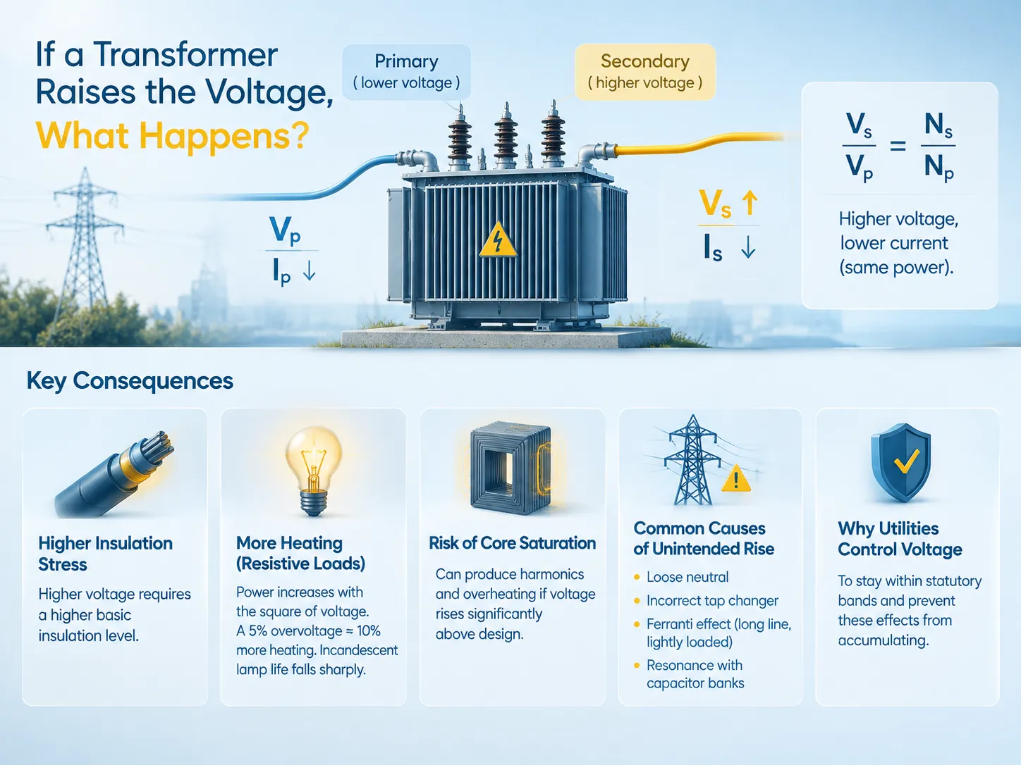
簡潔に言うと:トランスが電圧を上昇させると、二次側の電圧は一次側の電圧よりも高くなり、巻数の比に従います — Vs/Vp = Ns/Np — 一方、電流は同じ比率で低下します。これは、トランスが電力を転送するが、電力を生成しないためです。この側面は、トランスの最初で最も重要な結果です。この最初の結果の後に、さらに四つの結果があります。絶縁体は増加した誘電ストレスに耐えなければならず、つまり高電圧で動作する巻線はより良い絶縁を持たなければなりません。抵抗性機器は、電圧の二乗が増加するため、より多くのエネルギーを受け取ります。つまり、電圧が5%上昇すると、抵抗性機器の加熱はほぼ10%上昇します。電圧が許容電圧レベルを超えると、白熱電球は光を失います。コアインダクタは、電圧が設計範囲を大きく超えると飽和します。.
トランスが電圧を上昇させる方法
トランスは、完全に静的なコンポーネントで構成されており、巻線間に電気的接続がないデバイスです。これは電磁誘導を通じて機能します。言い換えれば、一次巻線には交流が流れ、それによって変化する磁場が生成されます。その後、その変化する磁場が二次巻線に電圧を生成します。生成された電圧は、一次電圧に二次巻線と一次巻線の比を掛けたものに等しいです。.
トランスの二次巻線で生成される電圧は、そのワイヤーの巻数と一次巻線の巻数の関係に依存します。例えば、二次巻線のワイヤーの巻数が一次巻線の二倍であれば、二次コイルの電圧も一次コイルの電圧の二倍であると言えます。この巻数比の関係が、トランスが電圧を昇圧または降圧する能力を与え、トランスがもたらす利点を説明します。これには、逆に使用することも含まれます。.
トランスのサイズと容量の唯一の制限は、コア設計によって決まります。コア内の磁束密度は、コイルに加えられた電圧に比例して増加します。したがって、電圧が高くなるほど、コアはより飽和状態になります。したがって、コアが飽和点に達すると、フラックスのラインはそれを通過できなくなります。これらの制限を生み出す基本的な構造を理解することが出発点であり、私たちのガイドに示されています。 配電トランスの基本.
製造時に比率が固定されている場合、実際の出力電圧を支配するパラメータは、タップ巻線の回路内のターン数です — これがタップチェンジャーが存在する理由です。それらの設定とその他の名板データは、私たちの説明の対象です。 トランスの仕様, 、これはバイヤーが電圧の問題が故障であると仮定する前に見るべき場所です。.
保存の法則: 電圧上昇、電流下降
電圧を上げる最も重要な結果はしばしば見落とされます: 電流が減少します。.
理想的なトランスはエネルギーを損失なく伝達し、したがって両側の電圧と電流の値は同じでなければなりません。二次側の電圧が上がると、一次側で同じ電流が流れている二次側の電流はそれに応じて減少します。言い換えれば、トランスが二次側で240 Vで100 Aの電流を供給し、一次側で120 Vで200 Aを消費している場合、両側の電力は等しいです。なぜなら、新しい電流は生成されないからです。.
| 数量 | 関係 | 二次電圧を上げる結果 |
|---|---|---|
| 電圧 | Vs/Vp = Ns/Np | ターン比に比例して上昇 |
| 電流 | Is/Ip = Np/Ns | 逆比例で減少 |
| 電力 | VpIp ≈ VsIs | 損失を除いて変わらない |
| ソースが見たインピーダンス | Zp = (Np/Ns)² × Zs | ターン比の二乗によって変換される |
インピーダンスの行は考慮すべき重要な要素です。なぜなら、それは最も直感に反するからです。二次側の負荷は、ソースによって自身ではなく、ターン比の二乗で掛けられたものとして見られます。電圧が10倍に増加すると、1Ωの負荷は一次側から見ると0.01Ωのように見えます。これがオーディオおよびRF回路におけるインピーダンスマッチングが発生する方法であり、一定の負荷が単純な計算から予想されるよりもはるかに高い一次電流を引き出すステップアップトランスの現象の正確な理由です。.
実際のトランスは100%の保存を達成しません。巻線の銅損失とコア材料のコア損失は熱の形で放散されるため、効率は1と仮定されるのではなく、パーセンテージで表現されます。これがトランスが負荷の下で温かくなり、開放回路では冷たく保たれる理由です。損失自体は、最終的にトランスの寿命を制限するメカニズムの一部であり、私たちの記事で取り上げられています。 トランスが故障する原因.
インピーダンスと負荷に何が起こるか
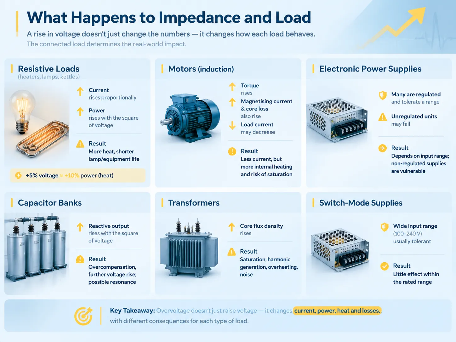
接続された負荷の性質は、接続された負荷がどのように反応するかを完全に支配し、したがって電圧の上昇の結果は設計仕様から運用上の懸念に変わります。.
| 負荷の種類 | 電圧が上昇したときの挙動 | 結果 |
|---|---|---|
| 抵抗負荷(ヒーター、白熱灯、ケトル) | 電流は比例して上昇し、電力は電圧の二乗に比例して上昇する | 加熱が増加し、ランプの寿命が急激に短くなる |
| モーター(誘導) | トルクは上昇するが、励磁電流とコア損失も増加する; モーターは電流では冷却されるが、コアでは熱くなる可能性がある | 電流の引き込みは減少するが、磁気損失は増加する; 電圧が公称値を大きく上回ると過熱する |
| 電子電源 | 多くは調整されており、範囲を許容する; 調整されていないものは故障する可能性がある | 入力範囲に完全に依存する; 非調整電源は脆弱である |
| コンデンサバンク | 無効出力は電圧の二乗に比例して上昇する | 過剰補償とさらなる電圧上昇; 共振の可能性 |
| トランス | コアのフラックス密度が上昇する; 設計点を超えた飽和と高調波生成 | 過熱、高調波歪み、可聴ノイズ |
| スイッチモード電源を持つ電子機器 | 通常、広い入力範囲(100-240 V)を持ち、許容範囲が広い | 定格範囲内ではほとんど影響がない |
抵抗負荷の行は興味深い観察を含んでいる。抵抗負荷では、電力は電圧の二乗に関連している。したがって、5%のような過電圧は、約10%の熱を生成することに相当する。加熱要素の場合、これは要素の寿命が非常に短くなることを意味し、エネルギーコストも高くなる。しかし、白熱灯に関しては、過電圧からの寿命の強い依存性により、さらに短い寿命を意味する。これは、過電圧によるユーザーへの実際の、測定可能で増加するコストのため、電圧調整の重要性の理由でもある。.
モーターの行は、一見すると思われるよりも微妙である。モーターがより多くの電圧を受けると、同じ機械出力で消費する電流が減少し、良いことのように見えるが、磁気回路に関しては状況はかなり異なる。理由は、電圧の上昇がコア損失を増加させ、電流が減少してもモーターが内部で過熱し、非常に高い電圧では鉄の飽和が始まるためである。.
The Physical Effects of Higher Voltage
In addition to the effect(s) on the load, increases in voltage also put stress on the transformer in four ways.
- Stress on insulation. Insulation stress increases with increased voltage, and as insulation stress increases, lifetime of the insulation decreases. As a consequence, a transformer with a higher winding voltage must also have a higher basic insulation level; also, for the same reason, lightning impulse withstand voltage becomes one of the items in the specification and not a detail.
- Partial discharge. When stress is high enough, a void or defect within the insulation may start discharging, which leads to gradual deterioration of that material. Partial discharge serves as a precursor of a failure but it is not a failure itself, and it is one of the side effects of overvoltage.
- Core saturation and harmonics. When a core is driven above its design magnetic flux density (material and configuration of the core determine the level of the magnetic flux that the core can withstand), the magnetizing current becomes distorted and starts containing some odd harmonics that result in increased losses, increased temperature, and may result in resonances somewhere else in the system.
- Increased audible noise. Magnetostriction–the dimensional change of the core due to the magnetization–also increases with increased flux density; thus, an overvoltage transformer produces significantly more audible sound than the same transformer at normal voltage levels.
These four phenomena have the common feature that makes overvoltage dangerous: they are cumulative and pretty much invisible. It happens so that an overvoltage transformer does not give any signs of trouble, it just ages more quickly, and failure happens sooner than expected.
Unintended Voltage Rise: The Causes
There are four chief reasons why voltage levels will be excessive other than being deliberately raised.
| 原因 | 機構 | How to recognise it | Response |
|---|---|---|---|
| Incorrect tap changer setting | The tap is set for a different supply voltage than the one present | Consistent, predictable offset across all loads; present at all times | Reset the tap to match the actual supply; verify with a measurement |
| Lost neutral | The neutral reference floats, so voltage divides between legs by load impedance | Voltages on two legs sum to the full line voltage; some loads see high voltage while others see low | Emergency: isolate and treat as a supply fault |
| Ferranti effect | On a long, lightly loaded line the capacitive charging current raises the receiving-end voltage above the sending-end voltage | Voltage rises as load falls; worst at night or in low-demand periods | Reactive compensation, or accept it if within limits |
| Capacitor bank resonance | Power factor correction capacitors resonate with system inductance, amplifying voltage at a harmonic frequency | Distortion and voltage rise correlated with capacitor switching | Detune or retune the bank; investigate harmonics |
| PV or generation backfeed | Embedded generation raises voltage at the point of connection when exporting | Voltage rises when generation is high and local load is low | Transformer tap adjustment, voltage regulation, or export limitation |
The simplest cause is a faulty tap changer. If the tap changer is set incorrectly, the transformer will supply the expected voltage all the time, and the solution would entail resetting it correctly after finding out the true input voltage instead of using the nominal voltage value. In the context of tap changers, there exist off-circuit (can be set only when the transformer is not energized) and on-load tap changers that can allow to perform their operation under load and typically function in accordance with a volt-regulating relay.
The Ferranti effect is another cause that presents a surprise. It is based on the fact that a long-way transmission or power supply line has capacitance distributed along its length, and when the very line is not loaded much, the capacitive current traveling through the inductance of the line will cause the voltage to increase instead of decreasing. The nature of the effect is proportional to the line length and inversely proportional to load capacity meaning that the effect is the most severe in case of long lines and low loads that is why a voltage drop problem can happen at night rather than when consumption is higher.
The Lost Neutral Case
This missed depth is the reason why there may not be general distinctions between this cause and other such reasons, as the answer is different in nature, viz. a crisis rather than an adjustment.
In the case of a split-phase supply, the centre tap of the transformer provides the neutral, which keeps both the line-to-neutral voltages at their normal levels. If the neutral connection is loose, corroded, or open at any point, such as at the transformer, in the service drop, at the weatherhead, at the meter base, or in the panel, the reference is lost. The two line conductors plus the loads connected between them and the neutral are in series for the whole line voltage, and the voltage is distributed depending on the impedances of the loads on either side.
The resulting effect is that a voltage rises on one side and falls on the other side. Thus, loads in the lightly loaded leg will take voltages almost equal to the full line voltage, whereas devices on the heavily loaded leg will note nearly no voltage changes. The voltage differences are due to the nature of the electrical appliances, since whenever any electric device is switched on, the balance is altered. The key symptom is burnt devices on one side and underperforming devices on its opposite side in parallel.
This is why a lost neutral should be viewed as an emergency of the supply and not as a regulation issue.The protective arrangements that limit damage in such events, and the role of the neutral in the grounding scheme, are covered in our guide to トランス接地の基本.
How Voltage Is Controlled
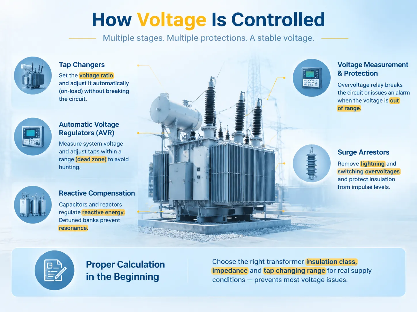
Voltage control is integrated into the system at multiple stages as both the expected and unexpected voltage variations are important.
- Tap changers. Off-circuit tappers set the voltage ratio and on-load tap changers change the ratio without breaking the electrical circuit under the supervision of the automatic voltage regulator.
- Automatic voltage regulators and compensators. They measure the voltage in the system and change tap to maintain the voltage in the range with dead zone to avoid hunting.
- Reactive compensation. Capacitors and reactors regulate the reactive energy which causes voltage variation due to load, detuned battery eliminates the resonance issue.
- Voltage measurements and protection. The overvoltage relay breaks the circuit or indicates the occurrence of the voltage level outside the acceptable range—last opportunity for voltage protection.
- Surge arrestors. They eliminate overvoltage coming from lightning and switching action and do not allow the insulation to operate beyond its impulse level.
- Proper calculation in the beginning. Choosing the transformer of the needed insulation class and impedance as well as the tap changing range for real supply conditions prevents most of the issues described in this article because this is the reason why the specification is the most important step.
For a site installing or replacing a distribution transformer, the practical step is to specify against the measured supply voltage and the expected load profile rather than against nominal figures. Our 配電変圧器の範囲 illustrates the parameters that should be pinned down — rated voltages, tap range, impedance, insulation level and cooling class — because each of them determines how the unit behaves when the supply is not exactly nominal.
Voltage Limits and Standards
Utilities don’t attempt to keep voltage consistent; instead, they keep it within a band and the extent of that band defines what kind of variations equipment can withstand.
In North America, the main specification used is ANSI C84.1, which specifies for example the so-called Range A utilities (roughly ±5% of nominal) as a range within which equipment is expected to work and which is referred to as Range B or (approximately ±5.5%) range that is expected to be tolerated but not sustained. If we take 120 V service we get roughly 114-126 V for Range A and if we take 240 V services we get roughly 228-252 V.
In Europe, EN 50160 specifies the voltage characteristics of voltage in use and which states nominal voltage of 230 V and allowed variations in the surrounding space about ±10% during most of the time and also with the restrictions on harmonics, flicker and unbalance. Able equipment in the circuits designed for the European market will be able to work with these band characteristics of the voltage.
Practically this means that nominal voltage is probably a more exactly defined mean of the voltage which is required from the transformer. The transformer should be chosen in such a way that it provides correct voltage (nominal voltage) at some point in the band of available supply voltage and for the insulation to work normally at the top level of this band and for the load to be compatible with calculating this variation. In case something is happening in the supply and if some company’s supply has always been near a band edge, it would be better to adjust tap.
よくある質問
How does a transformer increase the voltage?
Utilizing electromagnetic induction and turns ratio for an electric transformer. It generates a magnetic field in the magnetic core through the process of inducing current. In case the secondary winding of the transformer has more turns than the primary winding, the voltage induced is proportionately high, meaning that the ratio Vs/Vp = Ns/Np applies. There is no logical connection between the branches and energy is not produced and thus the transformer performs the transfer of electrical power in a different circuit with an alteration of voltage – current ratio at the same time.
What would cause a transformer to have high voltage?
There are four main reasons. A tap changer that is incorrectly adjusted will give rise to a constant voltage shift regardless of the situation and can be corrected by resetting the tap based on the supply voltage measured. An interrupted neutral will cause the floating of the reference neutral thus resulting in a rise of voltage in one phase but a fall in another, meaning it is a supply emergency instead of adjustment. Ferranti effect will result in an increase of the receiving end voltage due to capacitive charging in long unloaded lines, reaching the peak in minimal loading. The resonance of the capacitor bank and the inductiveness of the system will boost the voltage. The embedded generator project will export power in unloaded systems as well making it a more frequent cause of voltage rise nowadays.
What happens if the voltage increases?
The scenario can be described as follows: In the case of a transformer operating under a constant load under which the current rises, the current will be inversely proportional for this load as a transformer can provide power without generating it. Constant loads will consume power as resistive load obtaining approximately 10 percent more heat under 5 percent overvoltage. Power varies in direct proportion to voltage in the power square; therefore, resistive load will make heating element life less. Core losses in motors and magnetising current increase while running current smay decrease, therefore motor will be hotter centrally. Insulation will be under greater electric voltage and will undergo wear faster, therefore with prolonged overloading there are chances of getting through the discharges. Saturation takes place in transformers and motors, so they generate harmonics as well as heat. And in any case, the transformer behind the affected one will have louder humming at high flux density.
How does a transformer affect voltage?
The electrical transformer manages the proportion of voltages in the primary and secondary circuits through the turns ratio, and in this mechanism, it performs three major functions. First, the transformer steps up or steps down the voltage, depending on which circuit has a bigger number of turns. Next, it performs voltage regulation not too well, because when the load increases, the output voltage decreases due to the drop in impendant voltage in relation to current value, which is expressed in the percentage of impedance on the nameplate. Finally, the transformer has taps to regulate voltage either off the circuit during installation or when the relay comes to operate. The voltage at the output of the transformer will depend not only on its operation but also on the load profile and state of supply network.
Does raising the voltage reduce losses?
The answer depends on where the losses are taken into account, either in the transmission line or at the receiving end. For any fixed amount of power, increasing the voltage lowers the current, and the resistive losses in a conductor depend on the square of the current, thus leading to significant decrease in the transmission losses. However, this effect takes place only in the transmission part of the line. Once the voltage is increased when the power is being consumed, the resistive load will be consuming more power and increasing the losses in the load. It is important to distinguish between these two conditions; therefore, high voltage can be regarded as efficient in transmitting the power and at the same time overvoltage leads to energy losses and even shorter service lifetime of the equipment used.
参考文献
- IEEE — Transformer Loading and Insulation Coordination Standards
- International Electrotechnical Commission — IEC 60076 Power Transformers and IEC 60038 Standard Voltages
- ANSI — ANSI C84.1 Electric Power Systems and Equipment Voltage Ratings
- CENELEC — EN 50160 Voltage Characteristics of Electricity Supplied by Public Networks
- U.S. Department of Energy — Power Quality and Distribution System Guidance
結論
When it comes to increasing the voltage in a transformer, it is evident that the output voltage will be dependent on the winding ratio. The output current will also decrease at the same ratio as the voltage increase due to the fact that transformers transfer power instead of generating it. After encountering the higher output voltage, the next step is to consider what effect it will make in the equipment operated with it. Resistive installations will require more power with voltage squared and produce more heat. Motors will operate with less current and increased core losses. Higher voltage will result in more quick ageing of insulation, more noise, and excessive harmonics if the voltage exceeds its threshold value. When it comes to the increase generation of this high voltage, the whole system is designed according to these pack of parameters like insulation, winding ratio, and tap. When the generation of high voltage is unintentional, its root cause determines what solution to apply. For instance, switching the faulty tap back to default or compensating for Ferranti effect.