


スイッチギアとスイッチボードは時々同一視されることがあります。これは契約書、メールでの送信、および特定の回路図に見られます。両者は共通の目的を持っていますが、実際にはそれぞれ独自のUL基準、製造プロセス、価格を持つ2つの異なるカテゴリです。したがって、サイズだけで混同すべきではありません。これら2つのカテゴリの違いは、設置が完了した数週間、数ヶ月、または数年後に明らかになります。時には、設置された機器の再設計に関する図面を受け取ることが原因であり、時には機器の定格と一致しない故障電流に関連する計算を受け取ることが原因であり、またある場合には、メンテナンス担当者がフィーダーのメンテナンスを行うためには、全体のアセンブリを無電圧にしなければならないことに気づくことが原因です。.
基本的に、UL 891 準拠のスイッチボードは「デッドフロント」製品であり、低電圧エネルギーを供給し、成形ケースまたは絶縁ケースの遮断器を使用して主装置およびフィーダー装置に低電圧を分配します(個別またはグループベースで)。一方、UL 1558 準拠のスイッチギアは、より金属製のエンクロージャを持つ低電圧遮断器であり、短絡定格およびバス、遮断器、ケーブルコンパートメントエンクロージャ用のUL 1066 準拠の遮断器を含みます。両方のタイプは1000 V未満での使用を意図しており、両方のタイプは低電圧エネルギーを分配するために設計されているため、一般的に見た目は似ています。ただし、スイッチギアは故障に耐え、故障耐性定格により運転を継続することができます。コストとスペースが要因である場合はスイッチボードを選択し、システムをオフにせずにメンテナンスを行う必要がある場合はスイッチギアを選択してください。同様の原則は、IEEE基準に準拠した金属エンクロージャおよび遮断スイッチギアタイプにも当てはまります。Subian Electricは、オープンカットスイッチギアと低電圧スイッチギアの両方のスタイルの機器を提供しています。.
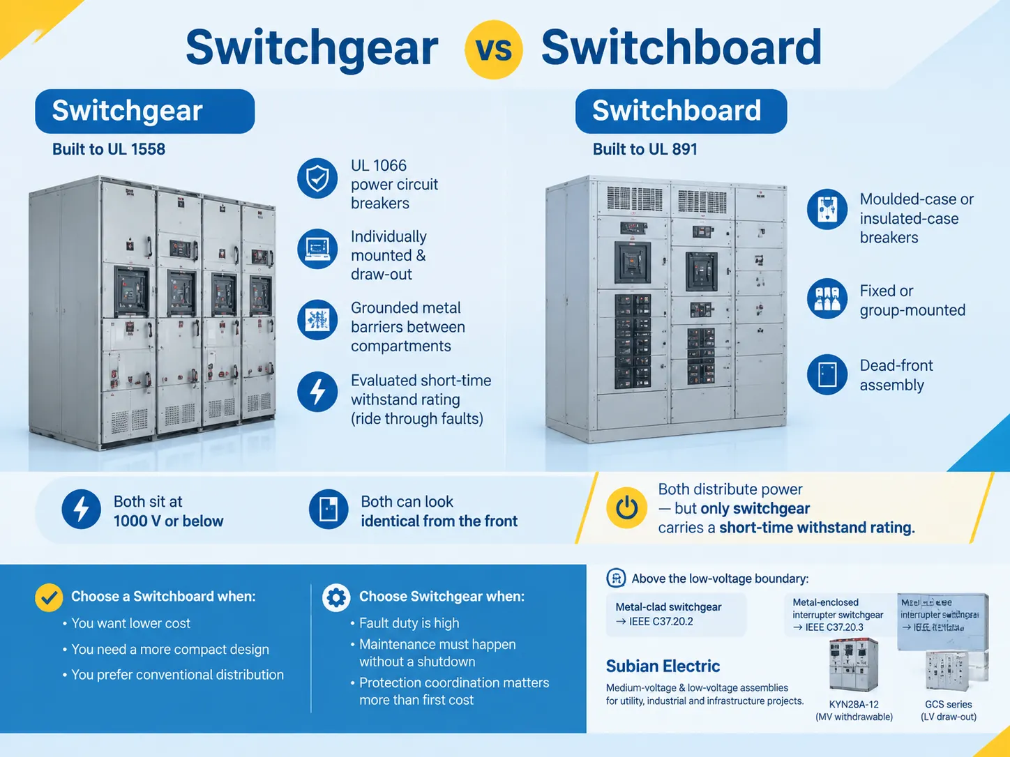
短い答えと、それがサイズに関するものでない理由
スイッチボードは2つのグループの中で比較的安価な機器であり、スイッチギアは高価で大きな機器であると言うことはできますが、これだけでは2つのアイテムの選択をするには不十分です。スイッチボードは最大1000 Vの定格を持ち、最大200,000 Aの利用可能な故障電流に対処できる一方で、スイッチギアのラインは中規模ビジネスが決して必要としない定格を持つことがあります。.
�¤のアイテムの真の区別要因は、故障発生時および保守時のパフォーマンスです。スイッチボードは、ブレーカーがほぼ瞬時にトリップすることによって故障を中断することを目的としています。それに対して、スイッチギアは特定の時間、通常は30サイクルの間、故障を処理できるように製造されており、メインスイッチが閉じたままで他の機器が動作し続ける中で、近くのデバイスによって下流の故障をクリアするのを助けます。.
他のすべての違いのポイントは、このポイントに従います。これには、コンパートメントの区分、使用される接地手段、引き出し機構、変電所内のスペース、アクセスルール、価格が含まれます。機器の運転を停止して保守を行うことが可能であり、ローカル故障が全施設の電力を切断する可能性がある場合、スイッチボードを最良の解決策として提案できます。中断のない運転を確保する必要がある場合、スイッチギアの高い価格は中断のないサービスに投資することを意味します。.
スイッチギアとは何か
北米における低電圧スイッチギアは、UL 1558に準拠し、ANSI/IEEE C37.20.1の構造およびANSI C37.51の試験基準に接続された低電圧金属封入型パワー回路ブレーカースイッチギアを指します。この基準は、1,000 V AC名目未満の機器に適用されます。2025年4月に発表されたUL 1558の第6版には、複数のソーススイッチギアに関する新しい要件も追加され、最初の改訂は2026年6月に行われました。.
それにもかかわらず、ブレーカーは電圧自体よりもカテゴリを定義します。スイッチギアは、UL 1066基準でテストされた低電圧回路ブレーカーで構成されており、100%の定格を持ち、メンテナンスなしでエンクロージャ内で機能し、故障の例外的な場合に完全なリモート操作を提供し、30サイクル連続で故障を通過することができます。通常、ブレーカーは別々に設置され、引き出し設計が施されています。.
構造自体はメンテナンスモデルを反映しています。コンパートメントは接地された金属組立によって互いに分離されており、各ブレーカーは他のブレーカーから隔離されています。ケーブルおよびバス用のコンパートメントも互いに分離されています。バリアの使用により、1つのキュービクルから他のキュービクルへの故障の伝播が排除され、他のタイプのスイッチボードに対してスイッチギアのより深いフットプリントを設計する必要性が生じます。.
通常、スイッチギアのラインアップは、メインサービス機器、重要なフィーダー分配、複数のソースおよびメイン-タイ-メインの配置、発電機の並列接続ポイント、保護リレー、測定機器、通信および監視デバイス、そしてますます頻繁にアークフラッシュ削減アイテムで構成されます。この構造は、最終的にパフォーマーが機器の性能を達成することを可能にし、単にその特性を仮定するのではなくなります。金属封入構造のアセンブリレベルの定義は、私たちのメモに記載されています。 金属封入スイッチギア.
スイッチボードとは何か
北米で知られているスイッチボードは、UL 891に従って構築されたデッドフロントアセンブリです。ULソリューションによると、UL 891は北米におけるデッドフロントスイッチボードの設置に関して最も広く使用されている標準とされています。言及されている標準は、電圧定格が1000Vを超えないスイッチボードに適用されます。故障電流能力に関しては、最大200,000 A rmsの能力があります。ただし、各スイッチボードには独自の特定の定格があり、その定格に関連するマークもあります。2025年3月の改訂では、複数ソーススイッチボード、強制空冷、緊急回路、およびサービス機器に関する追加または更新された要件がありました。.
ここでの主な安全属性はデッドフロントの側面であり、これは標準的な運用条件下で機器の前面からライブ部品にアクセスできないことを意味します。ただし、UL 891は異なるデバイスの区画化要件を規定していません。スイッチボードに見られるブレーカーは一緒にグループ化されており、保護機器は通常、UL 489基準に従ったモールドケースブレーカー、絶縁ケースブレーカー、またはUL 248ヒューズを備えたUL 98スイッチを特徴としています。モールドケースブレーカーは修理できない機器です。つまり、機器が稼働している間は、他のパラメータが明記されていない限り、通常は標準定格の80%で評価されます。.
この種の機器から生じる重要な結論が2つあります。1つ目は、デッドフロントアセンブリは通常、対応する電力の従来のスイッチギアよりも小型であることです。グループマウントにより、面積あたりの電力をより多く設置できるからです。さらに、UL 891は、スイッチボードが故障時に使用できる短時間定格を持つ可能性があることを意味しません。.
スイッチボードの内容物も多岐にわたります:主絶縁またはモールドブレーカー、ヒューズ式主スイッチ、主ラグ、フィーダーブレーカー、ヒューズ式フィーダー、銅またはアルミニウムブッシング、中性および接地ブッシング、カウンターシステム、サージ保護システム、ケーブル引き出しセクション、および監視システムが、スタンドアロンシステムとして配置されています。.
単一の配電システムでの相互作用
多くの組織では、スイッチギアとスイッチボードは同じ場所を争うことはありません。2つのシステムはプロジェクト内で異なる位置に配置されており、大規模プロジェクトでは両方を使用することが一般的です。電力会社から最も強力な機器を通じて電気を配分し、より弱いデバイスに電力を供給する蒸留プロセスが行われます。電力供給者またはサービストランスは、電気機器の主要なエネルギー源です。次のレベルの電力配電回路は下位にあり、その後に分岐回路レベルが続きます。実際、最初のレベルと第二のレベルの区別が、UL 891またはUL 1558機器を使用するかどうかの仕様を決定する要因となります。.
購入プロセスにおいて、バイヤーが誤りを犯す原因となる別の深刻な名称の問題があります。例えば、IECベースの市場では、大規模な主配電システムを「スイッチギア」と呼ぶことが一般的であり、これは変圧器や他の電力線を含む広い用語です。このような場合、バイヤーはUL 891スイッチボードを購入すべきであっても「スイッチギア」という用語を使用します。逆の状況も発生する可能性があり、バイヤーがUL 1558の引き出し式回路ブレーカーを使用する仕様の状況で「スイッチボード」を要求することがあります。このような海外プロジェクトに関わる際には、一般的な用語ではなく、使用される基準に従ってプロジェクトの種類を明確にすることが重要です。.
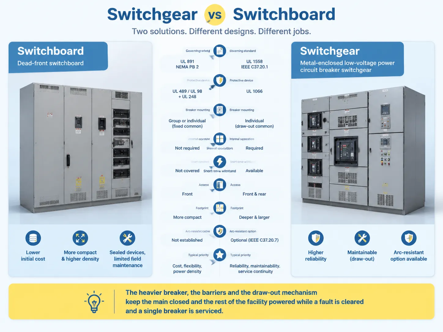
スイッチギア vs スイッチボード: サイドバイサイド
| 要因 | スイッチボード | スイッチギア |
|---|---|---|
| 規定標準 | UL 891; NEMA PB 2 レガシー | UL 1558; IEEE/ANSI C37.20.1; ANSI C37.51 |
| 製品説明 | デッドフロントスイッチボード | 金属封入低電圧電力回路ブレーカー スイッチギア |
| 保護装置 | UL 489 モールドケースまたは絶縁ケースブレーカー; UL 98 スイッチとUL 248 ヒューズ | UL 1066 低電圧電力回路ブレーカー |
| ブレーカー取り付け | グループ取り付けまたは個別取り付け、通常は固定 | 一般的に個別取り付けで引き出し式 |
| 内部分離 | デバイス間の分離は不要 | ブレーカー、バス、ケーブルコンパートメント間にバリアが必要 |
| 短時間耐久 | UL 891の対象外 | 評価された構成で利用可能 |
| 故障動作 | デバイスは高故障時に意図的な遅延なしでトリップ | 故障に耐え、通常は30サイクルまで動作可能 |
| メンテナンスアプローチ | 密閉デバイス、限られた現場メンテナンス | バスが通電している状態でメンテナンス可能な引き出し式ブレーカー |
| アクセス | 前面アクセス標準 | 前面および背面アクセス標準 |
| フットプリント | 通常はよりコンパクトで、高い電力密度 | 通常はより深く、より大きい |
| アーク耐性オプション | Not established by the UL 891 listing | Optional, separately specified and evaluated per IEEE C37.20.7 |
| Typical priority | Installed cost, flexibility, power density | Reliability, maintainability, coordination, service continuity |
By reading alongside the short-time withstand row, the rest of the table makes sense. The heavier circuit breaker, the barriers, and the withdraw mechanism are all designed to do one thing: keep the main circuit closed and the facility energized while a fault downstream is cleared and one circuit breaker is maintained.A representative low-voltage assembly built on that logic is described in our GCS low voltage draw-out switchgear.
The Three Types of Switchgear, and the Three Levels of Switchboard
When it comes to classifying equipment, the next logical step will be enquiring what construction class is being dealt with. As it happens, the construction class criteria are clear and straightforward. There are three construction classes for the switchgear, as defined by the National Electrical Manufacturers Association. The rest, including compact switchgear, arc-resistant design, gas-insulated equipment is just a modified version within the basic classes.
| タイプ | 標準 | 電圧範囲 | Distinguishing feature |
|---|---|---|---|
| 金属封入低電圧電力回路ブレーカー スイッチギア | IEEE C37.20.1 / UL 1558 | Up to 1000 V AC nominal | Compartmentalised LV assembly with UL 1066 draw-out breakers |
| Metal-clad switchgear | IEEE C37.20.2 | 5 kV to 38 kV, extended to 48.3 kV | Draw-out breakers, grounded metal barriers on all four compartments, automatic shutters, mechanical interlocks |
| Metal-enclosed interrupter switchgear | IEEE C37.20.3 | Above 1 kV up to 48.3 kV | Interrupter switches with power fuses; performance-based rather than structurally prescriptive |
The importance of the metal-clad clause must be understood as the standard is more prescriptive than aspirational. Thus, IEEE C37.20.2 realizes that the breaker, main bus, cable, and low-voltage compartments need to be separated by grounded metal barriers with no intentional openings between them; that the interrupting device is removable with connected, test, and disconnected positions; that there are automatic shutters protecting the primary stabs once the breaker is taken out; and that there are mechanical interlocks that prevent any closed breaker from being racked out or a wrong positioned breaker from being closed. The continuous ratings of the main bus generally fall within the ranges of 1200 A, 2000 A, 3000 A, and 4000 A.
Meanwhile, IEEE C37.20.3 does not share the same approach. Unlike the previous standards, this one governs the metal-enclosed assemblies in which switches interrupt load current inside the grounded enclosure using interrupt switches and fuses instead of the draw-out breakers. Metal-enclosed switchgear is lighter, more compact, and less expensive thus providing a desirable solution for feeders operating rarely while being below the fault levels consistent with draw-out breakers. One of the popular warnings within the industry is relevant for the situation with metal-clad switchgear since it is true that all metal-clad switchgear enables one type of metal-enclosed switchgear yet one cannot say vice versa without proving o the compliance with all previous statements.
With respect to cases when arc resistance is called for it should be emphasized that arc resistance would be mentioned in a specific way and that would be covered by IEEE C37.20.7 which refers to arc-resistant switchgear producing voltage of up to 52 kV and defining access ratings, such as: Type 1 serves only the people working in front of it while Type 2 facilitates the safety of people working in the front, behind, and on either side of it. It is worth mentioning that the arc-resistant construction is becoming widely used in data centers and industries in modern times and should be checked and verified independently of the type of equipment used to create the construction.
The rules regarding levels at the switchboard side are going in the opposite direction since the levels depend on their position in the system and not on their construction classification. As for UL 891, those switchboards are used for main and feeder distribution. UL 67 panelboards, rated within 1200 A, have the purpose of distributing the branch circuits while being mounted onto the wall. The commonly used sequence illustrates the power generating plant and transformer powering the switchboard which is further linked to the panel boards.Buyers comparing switchboards against legacy brand-name line-ups often arrive through a specific manufacturer’s catalogue; Siemens switchgear naming and positioning is a useful example of how one vendor organises an overlapping range, covered in our notes on Siemens switchgear.
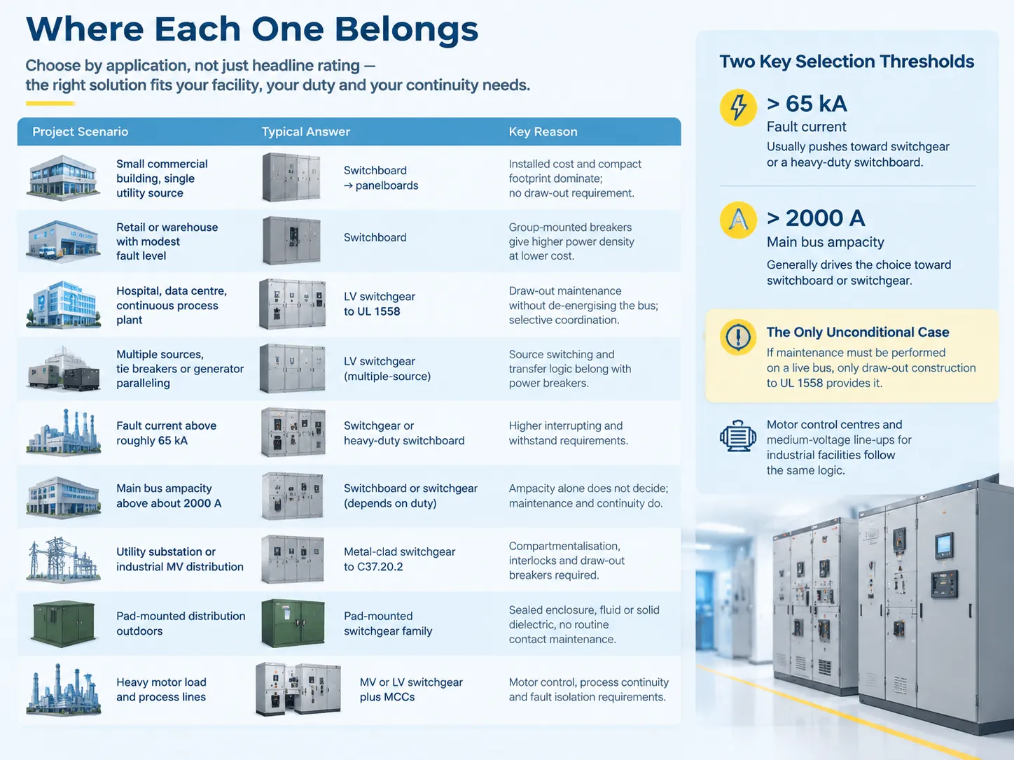
Where Each One Belongs
Deciding by application is more reliable than deciding by headline rating, because the applications cluster naturally around the maintenance and continuity requirements — and in practice they land in the same building types, from industrial manufacturing facilities to hospitals and data halls.
| Project scenario | Typical answer | 理由 |
|---|---|---|
| Small commercial building, single utility source | Switchboard feeding panelboards | Installed cost and compact footprint dominate; no draw-out requirement |
| Retail or warehouse with modest fault level | スイッチボード | Group-mounted breakers give higher power density at lower cost |
| Hospital, data centre, continuous process plant | LV switchgear to UL 1558 | Draw-out maintenance without de-energising the bus; selective coordination |
| Facility with multiple sources, tie breakers or generator paralleling | LV switchgear, multiple-source configuration | Both UL 891 and UL 1558 now address multiple-source arrangements, but source switching and transfer logic belong with power breakers |
| Fault current above roughly 65 kA | Switchgear or heavy-duty switchboard | Higher interrupting and withstand requirements push toward heavier construction |
| Main bus ampacity above about 2000 A | Switchboard or switchgear depending on duty | Ampacity alone does not decide; maintenance and continuity do |
| Utility substation or industrial MV distribution | Metal-clad switchgear to C37.20.2 | Compartmentalisation, interlocks and draw-out breakers required |
| MV feeder that switches infrequently | Metal-enclosed interrupter switchgear to C37.20.3 | Lower cost and smaller footprint suit the duty cycle |
| Pad-mounted distribution outdoors | Pad-mounted switchgear family | Sealed enclosure, fluid or solid dielectric, no routine contact maintenance |
| Industrial plant with heavy motor load and process lines | MV or LV switchgear plus MCCs | Motor control, process continuity and fault isolation requirements |
There are typically two selection limits not only in a way industry sometimes mentions that it’d be good to name them carefully, one of them being that it is not a standard itself. The point is that any projects where current flows in excess of around 65 kA normally find themselves utilizing the switchgear as well as heavy-duty switchboards instead of conventional ones. Moreover, if the choice of the bus is around 2000 A, you can bet it is either switchboard or switchgear and turned down anything that lies in the area of a panelboard.Motor control centres and medium-voltage line-ups for industrial facilities are built to the same logic — an example of the MV and LV assemblies used in that combination is described in our KYN28A-12 withdrawable AC metal-enclosed switchgear.
How to Specify the Right One
The following specifications are presented according to the sequence in which the information on them is finally collected. The commonest way for projects to procure the wrong model is by jumping from the equipment specification to the category, before the fault study has been done.
- Determine the existing fault current. It is a project requirement to conduct a short-circuit analysis. An equipment’s short-circuit rating must match or exceed the fault current at the equipment terminals, as per NEC 408.6. Thus, without this analysis, it is impossible to make reliable decisions regarding any downstream ratings.
- Indicate the equipment designations according to their standard numbers. For example, indicate “dead-front switchboard per UL 891” or “metal-enclosed low-voltage power circuit breaker switchgear per UL 1558 and IEEE C37.20.1”. Naming the standards eliminates ambiguity of the term “switchgear”.
- Define the maintenance approach even before pricing it out. Ask whether it will be possible to service any feeder with the rest of the site being energized. If the answer is “yes”, then the requirement becomes draw-out design, and it can no longer be reversed beyond this point without completely replacing the assembly.
- Confirm the short-time withstand criteria separately. It is important to note that UL 891 does not provide any short-time withstand current ratings, which means that if a design presumes a withstand period, this information should be explicitly mentioned in the UL 1558 specification. Do not assume anything by looking at switchboard quotations.
- Make sure the device class and the coordination study stay together. Selective coordination is possible in certain installations on both platforms, but power circuit breakers provide wider possibilities in terms of settings and delay. In case the design depends upon coordination at high fault levels, the class of the circuit breaker and the study should be treated as a single deliverable.
- Specifically indicate the requirement for arc-resistant construction only if this requirement is present. Arc resistance testing is to be performed in compliance with IEEE C37.20.7, while UL 891 and
- UL 1558 do not include any requirements regarding the arc resistance testing. Indicate the type of the equipment access required, Type 1 or Type 2, and ask for the testing results.
- Coordinate the layout of the entire room rather than only the equipment. Room requirements include space for equipment access, entry direction for incoming cables, back distance, space required for ventilation of forced-ventilated designs, and room needed to remove and reload the circuit breaker.
- Plan procurement in accordance with realistic lead times. Lead times for low-voltage draw-out switchgear reached 70-80 weeks in early 2024, which means that procurement decisions for equipment with long delivery times must be finalized at the schematic design stage. Treating switchgear as a last-minute purchase is how projects lose the commissioning window.
A deceptively common issue in manufacturing needs clearing up. It is when there is a specification for “switchgear” in the plans, but the buyer has instead brought in UL 891 switchboards at lower cost. The one-line diagram has been unaffected. However, the installation cannot achieve all the required ratings and thus operation of the plant can be jeopardized and the problem can go unnoticed until the failure occurs. In case switchgear is needed, it will be best if the plans indicate so and provide relevant standards.
よくある質問
What is another name for switchgear?
The official term is switchgear assembly – switchgear in IEEE C37.100.1 is outlined as term that encompasses switchgear assembly which includes switching, interrupting and controlling, metering, protective and regulating devices and enclosing structures. Similar concept in IEC market is an assembly of devices, hence the word has broader meaning there. For medium voltage construction terms are, respectively: metal-clad switchgear, metal-enclosed interrupter switchgear, compact switchgear related to IEEE C37.20.9. Old drawings of North America would refer to historical names of NEMA SG 3 and SG 5, which IEEE C37.20 has already replaced. At the facility itself the operators usually refer to switchgear simply as “gear”.
Is a breaker considered switchgear?
No. A circuit breaker is a component; switchgear is a component of the complete set. The importance of the distinction is that breakages and switchgear are governed individually, as in the case of UL1066 low voltage power circuit breaker and UL489 moulded case circuit breaker. After fitting, a breakage is part and parcel of a listed assembly, e.g. switchgear or switchboard assembly, and is subject to rating short circuit current capacity. Thus, the breaker class reflects the corresponding category of the installation: power circuit breaker refers to switchgear and case or insulated case circuit breaker refers to switchboard in every situation.
What are the three types of switchgear?
According to the American Institute of Electrical Engineers and the American National Standards Institute standards that provide coverage for construction within North America, there exist three classifications of machinery: namely, metal-enclosed switchgear circuitry that conforms with IEEE C37.20.1 and UL 1558 standards and has a capacity for operating at voltages of up to 1000V AC; metal-clad switchgear recognized as complying with IEEE C37.20.2 standards that operates with voltages within the range of 5kV through 38 kV and has a bus rating of 1200 A to 4000 A; finally, there is metal-enclosed switchgear that utilizes interrupter functions under standards of IEEE C37.20.3, which includes equipment rated higher than 1kV but within a voltage capacity of 48.3 kV. In addition, a third manner to categorize switchgear is by voltage class where switchgear machinery is divided into three groups: low voltage, medium voltage, and high voltage types.
What is the main purpose of a switchgear?
The goal is to provide controllability and survivability to the power system. This can be divided into four functions, which are often confused: constant carrying of the current without too much temperature rise, switching on and off circuits under load, interrupting the short-circuit and isolating the defective section, while keeping the rest of the system energized, and ensuring the safety of switching off so that people can work on the equipment. The construction features of the switchgear (barriers, draw-out mechanism, interlocks, shutters, withstand rating, etc.) are required for the last functions only. Hence, it is possible to use switchgear where unexpected outages are costly and where maintenance is carried out on the live system, while the use of switchboard works wherever it is not true.
参考文献
- IEEE Standards Association — C37.20.1, C37.20.2, C37.20.3, C37.20.7 and C37.100.1
- UL Solutions — UL 891 Switchboards, UL 1558 Switchgear, UL 67 Panelboards
- NEMA — PB 2 Deadfront Distribution Switchboards and SG series
- NFPA — NFPA 70 National Electrical Code, Article 408
- IEC — IEC 61439 and IEC 62271 series for assemblies and switchgear
- Eaton — application guidance on switchgear versus switchboards
- Schneider Electric — low-voltage distribution equipment documentation
- ANSI — C37.51 conformance test procedures
- Electrical Safety Foundation International — workplace electrical injury data
- OSHA — arc flash and electrical safety guidance
結論
Switchgear and Switchboards are two different types of electrical equipment. Each provides a unique function, has its own unique form factor, comes in many different types, etc. There are many different types of switchgear, but they are not the same as a switchboard.In order to ensure you are selecting the proper Switchgear or Switchboard, it is essential to follow the three rules outlined here. The first rule is to use the appropriate standard(s) when using either an Electrical Schematic Diagram or Architectural Document that specifies the switchgear or switchboard. Simply stating the common name of an item is not sufficient. The second principle states that you should select the maintenance program prior to determining the pricing of the equipment. A maintenance program cannot be added to the group type after pricing has been established, because the draw-out feature in a maintenance program, if not originally designed in, cannot be easily retrofitted. Finally, the third principle states that a short circuit analysis should be performed early in the project implementation process, as this analysis will help determine the type of switchgear or switchboard selections.