When a maintenance electrician in a Singapore hospital plugged the portable defibrillator into a regular wall socket to conduct a post-repair test, the technician was not depending on the circuit breaker present in the building to provide protection against electric shock caused by internal ground fault in the defibrillator. He relied on the isolation transformer — a specially designed unit that provided electrical isolation between the OR circuit and the main source of power in the building, provided a floating secondary circuit with no connection to the ground, and was equipped with line isolation monitor (LIM) that continuously monitored the circuit and would issue an alarm in case the impedance to ground went below a safe value. A single fault in the panel board would not cause a trip of the circuit breaker; in an isolated system, it does not generate a high fault current — the only thing that happens is a connection of one point of the floating system to the ground; the functioning of the rest of the system continues undisturbed. The role of LIM is to detect this condition and warn the personnel in order to complete the procedure without any abrupt loss of power in the course of operation. This is the fundamental principle of operation for isolation transformers — it is not only about stepping voltage up or down. An isolation transformer provides an electrically isolated circuit in which the occurrence of a single fault does not injure anyone and does not cause an interruption of the operation of the equipment. Knowledge about the emergence of the necessity of using isolation transformers and their principles of operation as well as the specification and installation of these devices must be possessed by any electrical engineer, facilities manager, or contractor working in a medical or industrial industry.

An isolation transformer can be described as a transformer with a 1:1 turns ratio (or any ratio where the voltages between primary and secondary sides are different), which provides galvanic isolation of primary and secondary windings. The second winding is electrically isolated from the first one (there is no closed circuit) and is generally set floating (ungrounded) or connected to ground through high impedance. This allows it to perform two essential safety functions. First, it ensures personnel safety against electric shock: when standing on a grounded surface, a person who is touching one of the wires of the isolated floating second does not feel any electrical shock, because there is no closed circuit through the ground back to the voltage source. There is an electric shock only when the person touches both conductors at once or when the second ground fault occurs on the other conductor. Second, it protects the equipment from ground-fault currents. In an isolated system, only a single ground fault does not cause a fault current to be too high, and the circuit does not trip. The key requirements for the design and installation of an isolation transformer are the dielectric strength of both windings (which has to withstand at least the operational voltage plus some margin; for example, 1500 V for a 120 V system), an electrostatic shield preventing possible capacitive connection of the primary and secondary sides, grounding of the enclosure and core (with the requirement that the core must be connected to the grounding conductor on the supply side), and use of a line isolation monitor (LIM) on the secondary side of the transformer. According to NEC 517, isolated electric power supplies (which are comprised of transformers, LIMs and ungrounded secondary conductors) have to be used in operating rooms and areas where wet procedures take place in medical facilities. This concept can also be applied in control systems and laboratories.
How an Isolation Transformer Works — and How It Differs from a Standard Transformer
A transformer isolates its two windings in that no direct connection exists between the two circuits and energy transfer takes place through the magnetic field of the core. But a conventional transformer is made to ensure that the secondary winding is grounded. The main reason for grounding is to provide a low-impedance path for fault current, so that any ground fault will result in a large current trip the overcurrent device immediately. This method is efficient and safe in many cases, but it has one drawback. When a person touches a live circuit while on a grounded object, they become a part of the fault circuit, and even if the current is very low, it still may cost him a life. However, an isolation transformer works in a different way. By providing the floating secondary winding, that is unconnected to the ground and connected through a high impedance, there is no low-impedance path between the conductors of the secondary and the ground. So even if a person touches one of the conductors while on a grounded surface, he is not breaking the circuit, because the secondary has no grounding.Dangerous current can only pass through a person if that person are in contact with both of the secondary conductors at the same time, or if a second ground fault occurs in the second conductor, while the first fault still holds. This principle (which indicates that a single ground fault cannot cause a shock, and therefore does not lead to the circuit being tripped) is the reason why the isolation transformers are utilized in places where a sudden stop of electric supply can result in an accident, and where ground-fault shocks can take place because of water, conductive liquids, or the presence of patients who are unable to leave the place.
The physical differences between regular transformer and isolation transformer are not great, but they still can be significant. Isolation transformer usually contains electrostatic shield, which is grounded conductive foil (screen) placed between primary and secondary windings and preventing capacitive coupling of the windings. The electrostatic shield is connected to the supply side grounding conductor, which allows diverting capacitive current to ground before it can reach the secondary circuit. Insulation system of the transformer should have a capability to sustain the full voltage between primary and secondary coils, plus some safety factor (in practice it is required to sustain 1,500 V AC or more for the 120 V system and 2,500 V AC or more for the 240 V system).For a look at the full range of isolation transformers and specialty transformers available for different applications, see the product catalogue at スビアン電気.

Where Isolation Transformers Are Required — and Where They Are Recommended
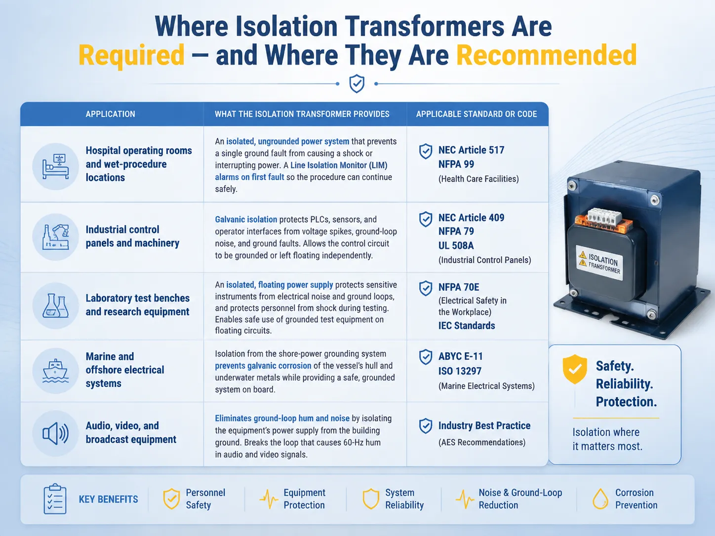
The table below summarises the most common applications for isolation transformers, the specific safety or operational requirement that the transformer addresses, and the applicable standard or code that governs the installation.
| アプリケーション | What the Isolation Transformer Provides | Applicable Standard or Code |
|---|---|---|
| Hospital operating rooms and wet‑procedure locations | An isolated, ungrounded power system that prevents a single ground fault from causing a shock or interrupting power. A line isolation monitor (LIM) continuously checks the impedance to ground and alarms if a first fault occurs. The system allows the surgical procedure to continue safely while the faulty equipment is identified and removed. | NEC Article 517 (Health Care Facilities), NFPA 99 (Health Care Facilities Code). The NEC requires isolated power systems in operating rooms and other wet‑procedure locations, unless the facility is designed under the “essential electrical system” provisions that allow an alternative approach. |
| Industrial control panels and machinery | Galvanic isolation of the control circuit from the power circuit, which protects the PLC, the sensors, and the operator interface from voltage spikes, ground‑loop noise, and ground faults on the power side. The isolation transformer also allows the control circuit to be grounded or left floating independently of the power system. | NEC Article 409 (Industrial Control Panels), NFPA 79 (Electrical Standard for Industrial Machinery). UL 508A is the standard for industrial control panel construction and requires that control transformers provide isolation between the power and the control circuits. |
| Laboratory test benches and research equipment | An isolated, floating power supply that protects sensitive instruments from electrical noise and ground loops, and that protects personnel from shock when working with exposed, energised conductors during testing and development. An isolation transformer allows the experimenter to connect a grounded oscilloscope probe to a floating circuit without creating a ground fault. | No single mandatory standard applies to all laboratories, but the principles of NFPA 70E (Electrical Safety in the Workplace) and the relevant IEC standards for laboratory equipment apply. Many universities and research institutions require isolation transformers on all test‑bench power supplies. |
| Marine and offshore electrical systems | Isolation from the shore‑power grounding system, which prevents galvanic corrosion of the vessel’s hull and underwater metals by the shore‑side ground current. The isolation transformer breaks the metallic connection between the shore‑side grounding conductor and the vessel’s grounding system, while still providing a grounded secondary for the vessel’s electrical system through the vessel’s own ground reference. | American Boat and Yacht Council (ABYC) Standard E‑11 (AC and DC Electrical Systems on Boats), ISO 13297 (Small Craft — Electrical Systems — Alternating Current Installations). Marine isolation transformers are a specific product category designed for the wet, corrosive, and vibration‑prone marine environment. |
| Audio, video, and broadcast equipment | Elimination of ground‑loop hum and noise by isolating the equipment’s power supply from the building’s grounding system. An isolation transformer breaks the ground loop that would otherwise allow 60‑Hz current to flow through the shields of the audio or video cables, which would introduce a hum into the signal. | No mandatory electrical code requires isolation transformers for audio equipment, but they are standard practice in professional recording studios, broadcast facilities, and live‑sound systems. The Audio Engineering Society (AES) publishes recommended practices for grounding and interfacing that reference isolation transformers. |

How to Specify and Install an Isolation Transformer Correctly
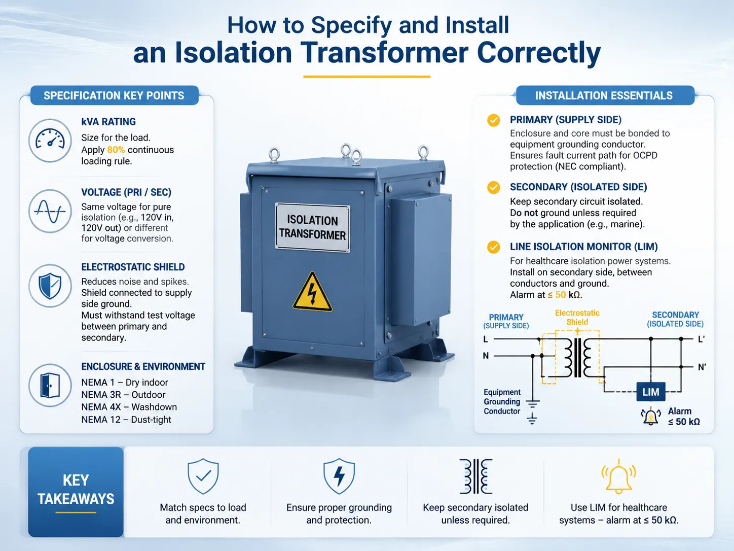
Proper specification and installation of isolation transformers require matching the electrical properties of the isolation transformer to the load and the appropriate protection scheme, as well as complying with the relevant grounding and bonding requirements. Among the key specifications are kVA rating (which must take into account the connected load — 80% continuous loading rule must be applied to ensure an adequate thermal margin and allow for the future increase in load) primary voltage and secondary voltage (the voltage may be either the same voltage in both primary and secondary sides — e.g. 120 V in, V out, in case of pure isolation — or different if it is necessary to convert voltage), electrostatic shield (especially during installation in applications where electrical noise, voltage spikes, or common-mode current on primary side can negatively influence the functioning of equipment on secondary side — the shield must be connected to the ground of supply side, and it must be capable of sustaining test voltage between primary and secondary), and enclosure type and environmental conditions (an isolation transformer in an electrical room can be installed in an open style, while isolation transformer in a factory or laboratory or in an environment requires enclosure with relevant rating — NEMA 1 is for dry indoor locations, NEMA 3R is for outdoor use, NEMA 4X is for washdown), and NEMA 12 is for dust-tight industrial enclosures.
The installation requirements are important for safety and good functioning of the isolated system. The enclosure and the core of transformer have to be in contact with the equipment grounding conductor on the supply side in accordance with NEC requirements for all transformers, including isolation transformers, so that the upstream overcurrent device will clear the fault occurring from primary to core short circuiting. The secondary circuit has to be wired and arranged as an isolated circuit, being grounded only if it is specified by means of some particular application (e.g. in marine applications when the secondary neutral needs to be grounded to the vessel grounding bus). On the other hand, line isolation monitor (LIM) for healthcare isolation power system has to be installed on secondary side, connected between secondary conductors and ground, and equipped with an alarm triggered at a prescribed threshold — practically 50 kΩ.
よくある質問
What is the difference between an isolation transformer and a standard transformer?
A traditional distribution transformer gives rise to a secondary circuit with a grounded neutral line. In this case, the neutral is kept in direct contact with the earth, such that a ground fault incident results in a large current which causes tripping of the overcurrent device.A separate type of transformer called an isolation transformer provides an ungrounded or floating line while other types of isolation transformers give rise to a grounded line with high resistance (i.e. high impedance). Hence, in case of a fault, a high fault current is not generated and no shock occurs or circuit tripping happens. Both kinds of transformers help provide galvanic isolation of the primary circuit from that of the secondary one.
Do I need a line isolation monitor with an isolation transformer?
According to the NEC, when the isolation transformer is utilized in a medical institution within an isolated power system, it is required that a line isolation monitor (LIM) be provided. However, in the case of industrial, laboratory, laboratory, and naval applications it is not always obligatory according to the code, although having it installed in all situations where it is important to ensure that the power supply remains undisturbed during a one-phase ground fault is highly recommended.
Can an isolation transformer be used for voltage conversion as well?
It is correct. The isolation transformer is capable of having any turns ratio, whether it steps up or down the voltage and yet provide galvanic isolation. A transformer with a turns ratio of 2:1 would provide isolation and step the voltage from 240 V to 120 V. The isolation and voltage conversion tasks are independent of each other and thus the transformer can achieve any of these tasks or both.
What is the electrostatic shield in an isolation transformer?
An electrostatic shield consists of a conductive grounded shield, usually in the form of copper foil or a screen, which is positioned between the primary and secondary windings. Its purpose is to minimize the capacitive coupling between windings, thereby blocking high-frequency electrical noise, voltage spikes, and common-mode currents created on the primary side from reaching the secondary side through the inter-winding capacitance. The shield is connected to the grounding conductor on the supply side in accordance with most of the isolation transformer standards applicable in the medical, laboratory, and industrial control field.
参考文献
- NFPA 70 (NEC) — Article 517 (Health Care Facilities) and Article 250 (Grounding and Bonding). The National Electrical Code requirements for isolated power systems in healthcare, and the grounding and bonding requirements for transformers and separately derived systems.
- NFPA 99 — Health Care Facilities Code. The comprehensive standard for electrical systems, including isolated power systems, in hospitals and other healthcare facilities.
- UL 60601 — Medical Electrical Equipment Safety Standard. The standard that defines the design, testing, and performance requirements for isolation transformers used in medical applications, including the dielectric withstand and the leakage‑current limits.
- ABYC E‑11 — AC and DC Electrical Systems on Boats. The American Boat and Yacht Council standard that requires isolation transformers or galvanic isolators on shore‑power connections to prevent galvanic corrosion and to protect personnel from shock in the marine environment.
The isolation transformer holds an exceptional position in the domain of electrical safety. Unlike with other products, where the breaker gets activated upon encountering a ground fault, the transformer does not cause the ground fault at all. In the event of detecting a hazard, the device does not automatically stop functioning, instead, it sounds an alarm and allows the people in the room to act on the information. Apart from that, instead of just separating two circuits, the isolation transformer creates a floating electric island with different properties compared to the rest of the building. From the aforementioned points, it is easy to see why, for the operation room, industrial control panel, laboratory desk or a ship, using the isolation transformer is not an option, but an obligation according to safety standards. Therefore, Subian Electric Company makes isolation transformers for medical, industrial, laboratories, and shipbuilding spheres.