


Um operador de subestação olhou para seu medidor eletrônico hoje quando uma tempestade chegou e mudou a linha de 110 kV de energia de 108 kV para 116 kV. Apesar disso, o barramento de 20 kV no lado secundário mostrou valores entre 19,9 e 20,1 kV ao mesmo tempo. O instrumento que funciona lá é chamado de comutador sob carga: a relação do transformador é corrigida passo a passo.
O artigo interpreta o que é a relação do transformador, como é calculada, qual é a relação entre relação do transformador e a estabilidade de tensão, como os comutadores mantêm a relação do transformador estável naquele exato momento, e quais consequências podem ocorrer se houver um erro na relação do transformador. Exemplos de cálculos são fornecidos no artigo juntamente com referências às normas IEC 60076 e IEEE C57, faixa típica de comutação, custo dos comutadores, entre outros.
O que é Relação do Transformador? (Definição e Fórmula)
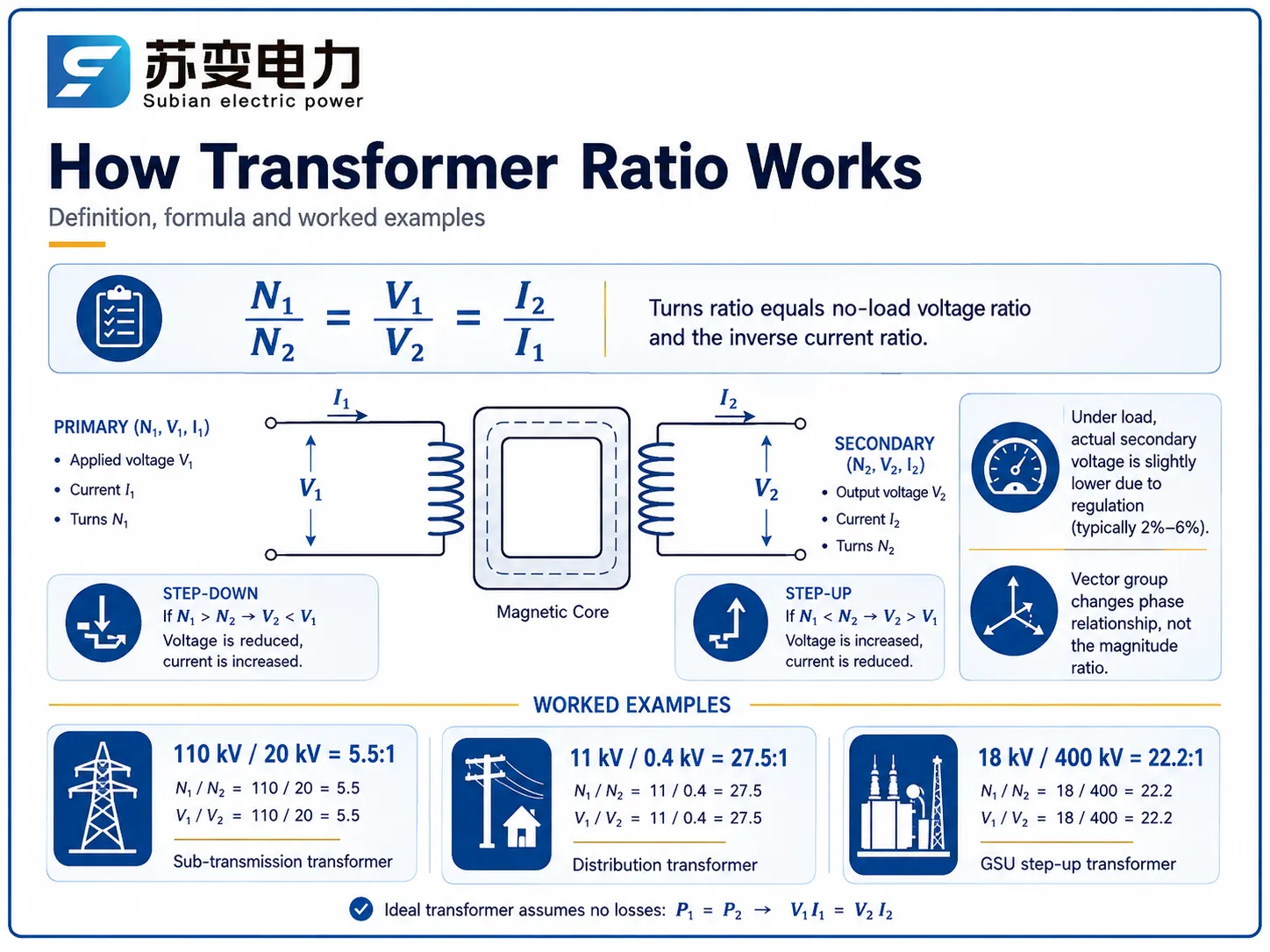
A relação do transformador ou relação de espiras define a relação entre o número de espiras do enrolamento primário e o número de espiras do enrolamento secundário. É igual à relação entre a tensão primária e a tensão secundária e à relação inversa das correntes primária e secundária no caso teórico.
N1/N2 = V1/V2 = I2/I1.
Transformadores reais não são ideais. Em transformadores reais, a reatância de fuga e a resistência do enrolamento geram quedas de tensão, fazendo com que a tensão real seja menor do que a tensão em vazio. A diferença na tensão em porcentagem é chamada de regulação de tensão que está em torno de 2%-6% dependendo das características dos transformadores.
A seguinte definição é usada de forma intercambiável nos contratos:
| Termo | Significado | Exemplo |
|---|---|---|
| Relação de enrolamentos | N1 / N2 (geometria pura do enrolamento) | 550 / 100 = 5.5 |
| Relação de tensão | V1 / V2 em vazio | 110 kV / 20 kV = 5.5 |
| Regulação | Queda de tensão de vazio para carga total | 2.5%–6% |
Como Calcular a Relação do Transformador: Exemplos Práticos
Determinar a relação é fácil se alguém conhece a tensão ou o número de espiras.
Por exemplo:
Um transformador de tensão 110 kV/20 kV tem 110:20 com 2200 espiras no primário, o que significa que há 400 espiras no secundário.
No caso de um transformador de alta tensão 18 kV – 400 kV, a relação se torna (400/18 = 22.2).
O transformador de distribuição geralmente tem uma relação de tensão de 11 kV/0,4 kV, o que significa que a relação é 11/0,4 = 27,5:1.
Devido à construção do autotransformador, que compartilha uma parte do sistema de enrolamento, ele tem um número menor de espiras para a mesma relação de tensão de 2:1.
No caso de transformadores que operam em um sistema trifásico, a tensão linha a linha deve ser usada, enquanto o grupo vetorial (Dyn11, YNd11) é importante em termos de determinar a relação do deslocamento de fase e a relação de magnitude do sistema.
Por que a Relação é a Válvula Reguladora da Rede
As flutuações de tensão em uma linha de transmissão ocorrem devido a vários fatores, nomeadamente modificações na carga, falhas de gerador, perdas de potência reativa e distância da fonte. Sem ajuste na relação, um alimentador pode experimentar flutuações de tensão de 5% a 10% ao longo de um único dia. A relação do transformador atua como o meio prático de compensar as vantagens da variabilidade de tensão, uma vez que há uma relação direta entre as voltas e a tensão de saída, com quaisquer alterações levando a flutuações correspondentes.
Os operadores do sistema devem manter a tensão dentro dos limites legais estabelecidos pelas regulamentações, que exigem manter a tensão em ± 5% no setor de distribuição e ± 10% no setor de transmissão. O método mais amplamente utilizado nesse processo é o OLTC, que ajusta a relação do transformador. De fato, o OLTC é tão amplamente utilizado que ter um transformador sem OLTC necessita de uma justificativa por escrito.
Mudadores de Tap: O Mecanismo Que Ajusta a Relação
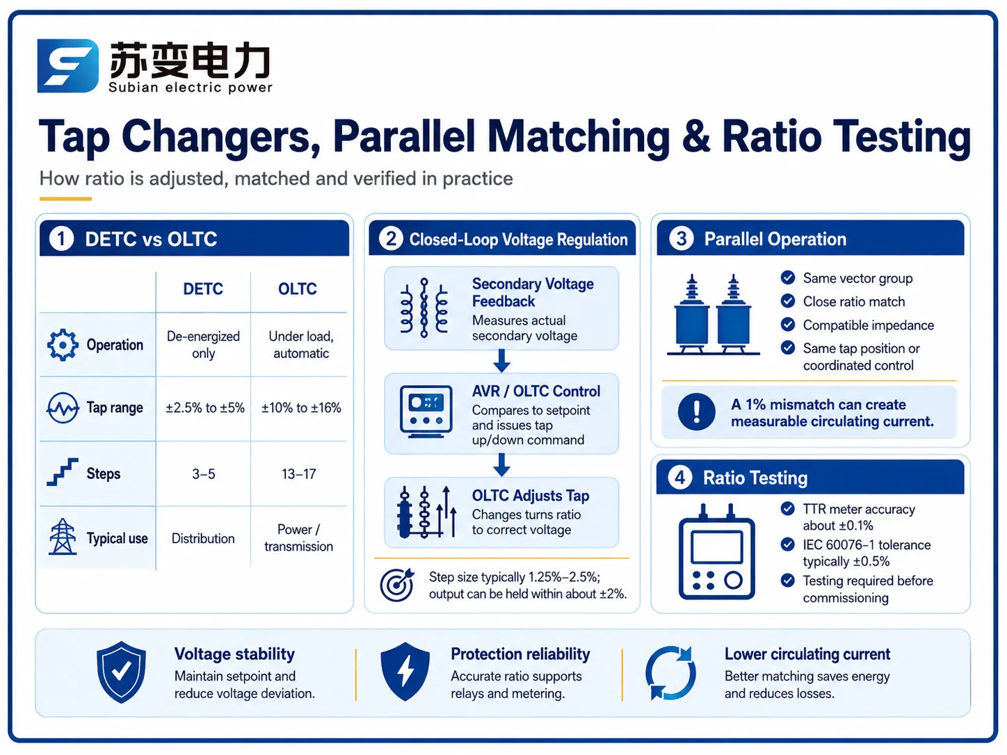
Existem duas famílias de mudadores de tap, e escolher entre elas é principalmente uma questão de ciclo de trabalho:
| Aspecto | Fora de Circuito (DETC) | Sob Carga (OLTC) |
|---|---|---|
| Operação | Desenergizado apenas | Sob carga, automatizado |
| Faixa típica de tap | ±2.5% a ±5% | ±10% a ±16% |
| Passos | 3–5 | 13–17 (1.25%–2.5% cada) |
| Capacidade de regulação | Somente sazonal | Contínuo, automático (±2% mantendo) |
| Prêmio de preço | Base de referência | +$15,000–$60,000 dependendo da classificação |
| Comum em | Transformadores de distribuição | Transformadores de potência ≥5 MVA |
Enquanto os OLTCs estão operando com corrente elétrica, eles usam resistores ou reatores e interruptores a vácuo rápidos para minimizar o arco elétrico nos contatos principais no processo de comutação de taps fixos. Um OLTC controlado por motor contemporâneo leva aproximadamente de 2 a 10 segundos para concluir um ciclo. Pode-se notar que o controlador, neste caso, usa feedback de tensão do lado secundário do transformador.
Correspondência de Relação para Operação Paralela
Ao usar dois transformadores para alimentar o mesmo barramento simultaneamente, as relações precisam ser ajustadas para serem próximas. Uma diferença nas relações de Δ% gera uma chamada corrente circulante (participando do circuito mesmo em condição de inatividade).
Um conselho é garantir que mantenhamos a corrente circulante abaixo de 10% da capacidade do transformador menor.
O efeito de uma diferença de 1% na relação é geralmente uma corrente circulante de 2%-5% da capacidade de dois transformadores com capacidade de 20 MVA / 110 kV, que depende da impedância (normalmente 10%).
Os transformadores devem ser operados de acordo com algumas condições básicas para isso, a saber: mesmo grupo de vetor, a relação deve corresponder e a impedância não deve variar mais do que 10%, se é que varia.
Para levar isso em conta, os operadores precisam mudar a posição do tap para cada transformador para torná-los iguais, e muitos dos AVR modernos têm um esquema de mestre-seguidor para esse propósito.
Efeitos de Relação Errada: Corrente Circulante e Problemas de Proteção
A operação incorreta do relé, devido à classificação do relé, pode levar ao mau funcionamento das proteções com configurações errôneas do relé, resultando em operação do protetor sem falha adequada ou falha em detectar defeitos internos reais devido a erros de 2%-5%.
Mudanças de tensão podem forçar a tensão ao longo do riacho para limites externos.
O desequilíbrio na situação de carga implica que uma unidade com uma relação mais alta consome uma parte considerável de potência ativa e reativa, levando à aceleração do seu envelhecimento.
É por isso que a verificação da relação se tornou um dos passos da comissionamento de acordo com os requisitos da IEC 60076-1, afirmando que a relação de tensão no tap principal não deve diferir em mais de ±0.5% do valor de projeto e cada tap deve ser verificado em relação aos dados da placa de identificação.
Métodos e Padrões de Teste de Relação
O teste de campo padrão é o teste de relação de espiras realizado com um medidor de relação de espiras de transformador (TTR):
| Método | Princípio | Precisão | Uso Típico |
|---|---|---|---|
| Medidor TTR (teste TTR) | Compara a tensão injetada e induzida em cada tap | ±0,1% | Comissionamento, manutenção de rotina |
| Verificação da relação de tensão sem carga | Aplicar tensão reduzida, medir ambos os lados | ±0,3% | Verificação no local |
| Relação de capacitância / teste de baixa tensão | Relação equivalente via acoplamento capacitivo | ±0,5% | Testes de tipo de fábrica |
Tanto os testes de fábrica quanto os testes no local se originam da IEC 60076-1 e IEEE C57.12.90. O teste TTR é considerado um teste diagnóstico primário, pois o movimento na relação entre diferentes testes realizados na mesma unidade muitas vezes indica uma espira em curto no enrolamento, tornando os testes anuais de relação um elemento essencial de monitoramento.
Relações Típicas e Faixas de Tap por Aplicação
| Aplicação | Relação Típica | Faixa de Tap | Mudador de Tap |
|---|---|---|---|
| GSU em uma usina de energia | 18/400 kV (22,2:1) | ±7.5% em 5 etapas | Fora de circuito, às vezes OLTC |
| Subestação de transmissão | 220/110 kV (2:1) | ±16% em 17 etapas | OLTC |
| Sub-transmissão | 110/20 kV (5,5:1) | ±12% em 13 etapas | OLTC |
| Potência industrial | 33/11 kV (3:1) | ±10% em 9 etapas | OLTC ou fora de circuito |
| Distribuição | 11/0,4 kV (27,5:1) | ±2.5% fora de circuito | Fora de circuito |
Transformadores de distribuição requerem apenas ajustes periódicos, portanto, tomadas fora de carga em passos de ±2.5% e ±5% são adequadas para contabilizar a variação sazonal da carga. Em contraste, transformadores de transmissão e subtransmissão são configurados com OLTC porque grandes grupos de clientes são diretamente afetados pela ação da tensão de transmissão sobre eles.
Impacto do Preço do Mudador de Tomada & Transformador
A escolha do mudador de tomada é um item real em qualquer orçamento de transformador. Faixas de planejamento:
| Transformador | Sem OLTC | Com OLTC | Premium |
|---|---|---|---|
| 5 MVA / 33 kV | $55.000–$90.000 | $75.000–$130.000 | +$15.000–$40.000 |
| 20 MVA / 110 kV | $150.000–$260.000 | $175.000–$320.000 | +$20.000–$60.000 |
| 50 MVA / 110 kV | $360.000–$700.000 | $400.000–$800.000 | +$25.000–$90.000 |
As taxas diferem de acordo com o tipo de especificações, a marca e a área. O alto custo envolvido em unidades conectadas à rede se paga em pouco tempo: o comutador sob carga (OLTC) pode recuperar rapidamente o custo porque mantém a tensão regulada e diminui as perdas de energia nos alimentadores.
Marcas & Como o Design de Relação Difere
A matemática da relação permanece a mesma, independentemente da empresa de origem — a física não está em negociação; no entanto, os fabricantes se distinguem com base no tipo de design do comutador, controle, gestão de qualidade e preços. Os padrões de confiabilidade são estabelecidos pelos comutadores MR (Maschinenfabrik Reinhausen) e ABB, à medida que empresas asiáticas utilizam cada vez mais designs de OLTC licenciados ou desenvolvidos internamente a preços mais baixos.
| Marca | País | Forças do Comutador | Preço Indicativo (20 MVA/110 kV, com OLTC) |
|---|---|---|---|
| Hitachi Energy | Suíça/Japão | OLTC proprietário, integração de AVR | $450.000–$700.000 |
| Siemens Energy | Alemanha | Opções de OLTC MR, controle digital | $430.000–$680.000 |
| Schneider Electric | França | Foco em distribuição, unidades MV | $280.000–$450.000 |
| TBEA | China | OLTC interno, escala | $180.000–$320.000 |
| Jiangsu Subian Electric Power | China | Relações e comutações personalizadas, OLTC MR ou interno | $160.000–$300.000 |
O custo é determinado pela especificação e área. Em projetos que requerem especificações de relação e comutação personalizadas – grupos vetoriais únicos, faixas de comutação especiais ou marcas específicas de OLTC – a Jiangsu Subian Electric Power é um parceiro confiável: fabrica transformadores de distribuição e potência com capacidade de 50 kva a 220 kV, fornece cotações para configurações de comutação individuais e instala os comutadores sob carga MR ou similares necessários. Cada unidade é entregue com registros de teste de relação em todos os comutadores sob a norma IEC 60076-1, e os preços de fábrica são geralmente 30%-50% mais baixos do que os preços para empresas europeias.
Perguntas Frequentes
Como é calculada a relação do transformador?
A relação do transformador é determinada pelo número de voltas na bobina primária dividido pelo número de voltas na bobina secundária (N1/N2), que é igual à relação de tensão sem carga (V1/V2). Por exemplo, o transformador aplicado a 110 kV/20 kV terá uma relação de 5,5:1, enquanto para o transformador de 11 kV/0,4 kV a relação é de 27,5:1. Devido à relação inversa, é evidente que em um transformador elevador (relação menor que um; como 0,045 para o transformador com tensão de 18/400 kV), a tensão de saída será alta enquanto a corrente de saída é baixa.
Qual é a tolerância na relação do transformador?
De acordo com a IEC 60076-1, a relação no comutador principal deve estar dentro de ±0,5% do valor da placa de identificação, e a mesma tolerância se aplica em cada posição de comutação, a menos que especificado de outra forma. Medidores de TTR de campo medem até ±0,1%, portanto, uma variação além de 0,5% em um teste de comissionamento justifica investigação para voltas em curto ou uma conexão errada.
Por que os transformadores precisam de comutadores para regulação de tensão?
Devido a flutuações na tensão da linha com base na carga, geração e distância da fonte, sem o ajuste de razão, o alimentador de distribuição pode flutuar 5%–10% ao longo do dia. O OLTC varia a razão em 1.25%–2.5% em etapas dentro de uma faixa de ±10% a ±16% para fornecer uma tensão secundária de cerca de ±2% automaticamente. Isso garante que os motores, eletrônicos e o equipamento do cliente estejam seguros contra sobretensão e subtensão.
O que acontece se dois transformadores em paralelo tiverem razões diferentes?
Uma corrente elétrica circula entre as duas unidades, mesmo quando não há carga vindo de fora. Em outras palavras, uma corrente circulante flui em um transformador mesmo quando está em modo de espera. Quando consideramos o caso de unidades de 20 MVA/110 kV, até mesmo uma discrepância de razão de 1% causará uma corrente circulante de cerca de 2%-5% da corrente nominal de plena carga. Além disso, se a discrepância aumentar, a corrente circulante também aumentará proporcionalmente. A ação dos operadores, que igualam a razão através do processo de seleção de tap, evitará que as correntes circulantes aumentem mais do que 10% da classificação do pequeno transformador.
Quanto um trocador de tap em carga adiciona ao custo do transformador?
O OLTC geralmente torna possível adicionar entre $15,000 e $60,000 ao custo de transformadores de potência classificados entre 5 MVA e 50 MVA, com transformadores de maior classificação custando mais. O investimento geralmente compensa devido ao melhor controle de tensão e menores perdas de energia, além da ausência de falhas de equipamento.
Referências
- IEC 60076-1: Transformadores de Potência — Geral — Define razão, tolerâncias, taps e requisitos de teste.
- IEC 60076-8: Guia de Aplicação — Orientação sobre tapping, operação em paralelo e aplicação de transformadores de potência.
- IEEE C57.12.00: Requisitos Gerais para Transformadores Imersos em Líquido — Requisitos norte-americanos para especificações de razão e tap.
- Fábrica de Máquinas Reinhausen (MR) — Referência da indústria para design e controle de trocadores de tap em carga.
- IEEE C57.12.90: Código de Teste para Transformadores de Distribuição, Potência e Reguladores Imersos em Líquido — Os procedimentos de teste incluindo testes de razão.
- US EPA: Programas de Eficiência de Transformadores — Contexto sobre por que o controle de tensão e transformadores eficientes são importantes em grande escala.
Conclusão
A razão do transformador funciona como um dispositivo de controle no sistema de energia – uma pequena e precisa mudança na razão de espiras feita pelos trocadores de tap permite manter a tensão dentro dos limites legais enquanto garante o fornecimento de energia ao longo de centenas de quilômetros de linhas de energia. O conhecimento da medição da razão, seus limites e operação em paralelo é crucial para todos os profissionais que especificam, testam ou prestam serviços a transformadores.
A razão também é a razão de tensão sem carga. Transformadores de distribuição podem operar com 5.5:1 até 27.5:1.
Transformadores com trocadores de tap em carga modificam a razão de -10% a +16% e posicionam a alavanca de tap em 13-17 etapas.
Transformadores devem ter a mesma razão e impedância para evitar a circulação da corrente. O teste de razão é obrigatório (IEC 60076-1, tolerância de ±0.5%) e permite detectar espiras em curto.
Se o seu projeto requer um transformador com uma relação específica, faixa de tomadas ou configuração de OLTC, Jiangsu Subian Electric Power pode projetar e fornecer transformadores de distribuição e potência de 50 kVA a 220 kV, com relatórios completos de teste de relação em cada unidade.