


Токовый трансформатор (CT) — это устройство, используемое в системе измерения/защиты для измерения больших значений тока/уровней, которые не могут быть измерены напрямую; он преобразует ток от 400, 1000 и 3000 A в полезное значение 5 или 1 A. Это изменение происходит при определенных условиях, которые должны соблюдаться устройством CT: полярность должна быть правильной, нагрузка должна быть точной, вторичная проводка никогда не должна быть подвержена открытому контурному соединению, пока ток течет. В руководстве содержатся спецификации о подключении проводки CT к измерительным, релейным и мониторинговым устройствам, как поэтапно настроить проводку и как должны быть подключены трехфазные модели.
В случае, если первичный ток или проводник, подключенный к устройству, допускается проходить через трансформатор P1 и P2, то показания, зафиксированные на вторичных клеммах P1 и P2, могут быть неверными из-за того, что S1 может не совпадать с P1 во всех случаях, что приводит к измерению напряжения тока на соединениях S1 S2. При использовании одного трансформатора оба соединения S1 и S2 не используются относительно всех трехфазных соединений. Нет необходимости в каком-либо другом методе подключения, если используется один CT, так как это всегда будет прямое соединение для двух S1 и S2. В случае трехфазной проводки трансформатор должен быть подключен с использованием метода соединения “Y” или звезда, при этом S1 подключается к трем входам приборов, где использование соединений S2 осуществляется в точке соединения, где S2 будет подключен к общему звездному пункту независимо от того, какой из двух вышеуказанных методов используется.
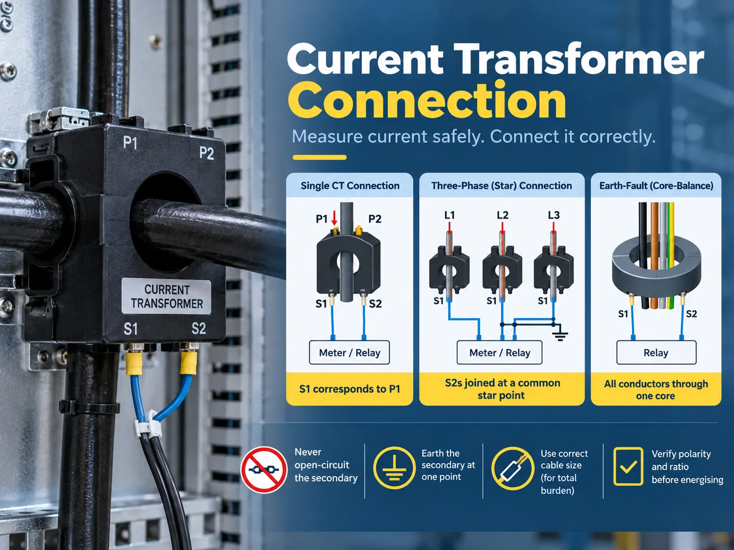
Что делает токовый трансформатор и почему важно подключение
CT — это специализированные трансформаторы, которые могут работать только одним способом: принимая первичный ток и производя пропорциональный вторичный ток, гарантируя изоляцию от первичной цепи. Токовый трансформатор 400/5 производит пять ампер на вторичной стороне, когда первичный ток составляет 400 ампер. Кроме того, он обеспечивает два с половиной ампера при половинной нагрузке, и подключенный счетчик или реле интерпретируют эту информацию и возвращают ее к первичному.
| Тип CT | Конструкция | Типичное использование |
|---|---|---|
| Барный первичный (окно) CT | Первичный — это фиксированный бар или шина, проходящая через окно | Распределительное оборудование, панельное измерение, модернизация вокруг существующих шин |
| Обмоточный первичный CT | Первичный — это обмотка, выведенная на клеммы (P1/P2) | Приложения с низким и специальным коэффициентом |
| Разделенный сердечник CT | Зажимы вокруг существующего проводника без отключения | Модернизация мониторинга энергии, субизмерение |
| Вводной CT | Встроен в ввод трансформатора или выключателя | Защита трансформатора и распределительного оборудования |
| Ядро-баланс (нулевая последовательность) CT | Все фазные проводники проходят через одно ядро | Обнаружение земного короткого замыкания и чувствительное измерение утечки |
Существует два важных фактора, которые показывают, как должен быть подключен трансформатор тока (CT). Соотношение для вторичного тока означает, сколько тока CT будет предоставлять для определенного первичного тока (например, 400/5 или 1,000/1). Нагрузка в VA указывает на количество нагрузки (учет и релейная защита), которая должна быть подключена к CT без влияния на его производительность. Таким образом, если CT работает в соответствии с правильным соотношением, но неправильно нагружен, показания не будут точными.
Клеммы и полярность: P1, P2, S1, S2
Клеммы CT следуют установленной конвенции, согласно которой проводка всегда однозначна, как только буквы поняты:
| Клемма | Значение | Правило подключения |
|---|---|---|
| P1 | Первичная сторона, помеченная полярностью | Обычно обращена к источнику (входная сторона проводника) |
| P2 | Первичная сторона, не помеченная | Обращена к нагрузке |
| S1 | Вторичная, соответствует P1 | Подключается к входу прибора, помеченному S1 (или входу “линии”/полярности) |
| S2 | Вторичная, соответствует P2 | Подключается к входу прибора, помеченному S2, или к звезде/общей точке в трехфазных схемах |
Правило полярности является основной причиной сбоев при наладке. Поскольку S1 всегда должен соответствовать входу S1 прибора, а P1 - источнику, изменение ориентации CT или перехода от S1 к S2 приведет к тому, что измеренные токи будут перевернуты. Приложения с защитой, чувствительной к направлению, могут также потерпеть неудачу, как и показания мощности (кВт), где импорт может отображаться как экспорт. С другой стороны, K и L как обозначения могут использоваться некоторыми производителями, принцип остается тем же (K соответствует P1, а L - P2), что означает, что табличка должна диктовать проводку, а не образ жизни.
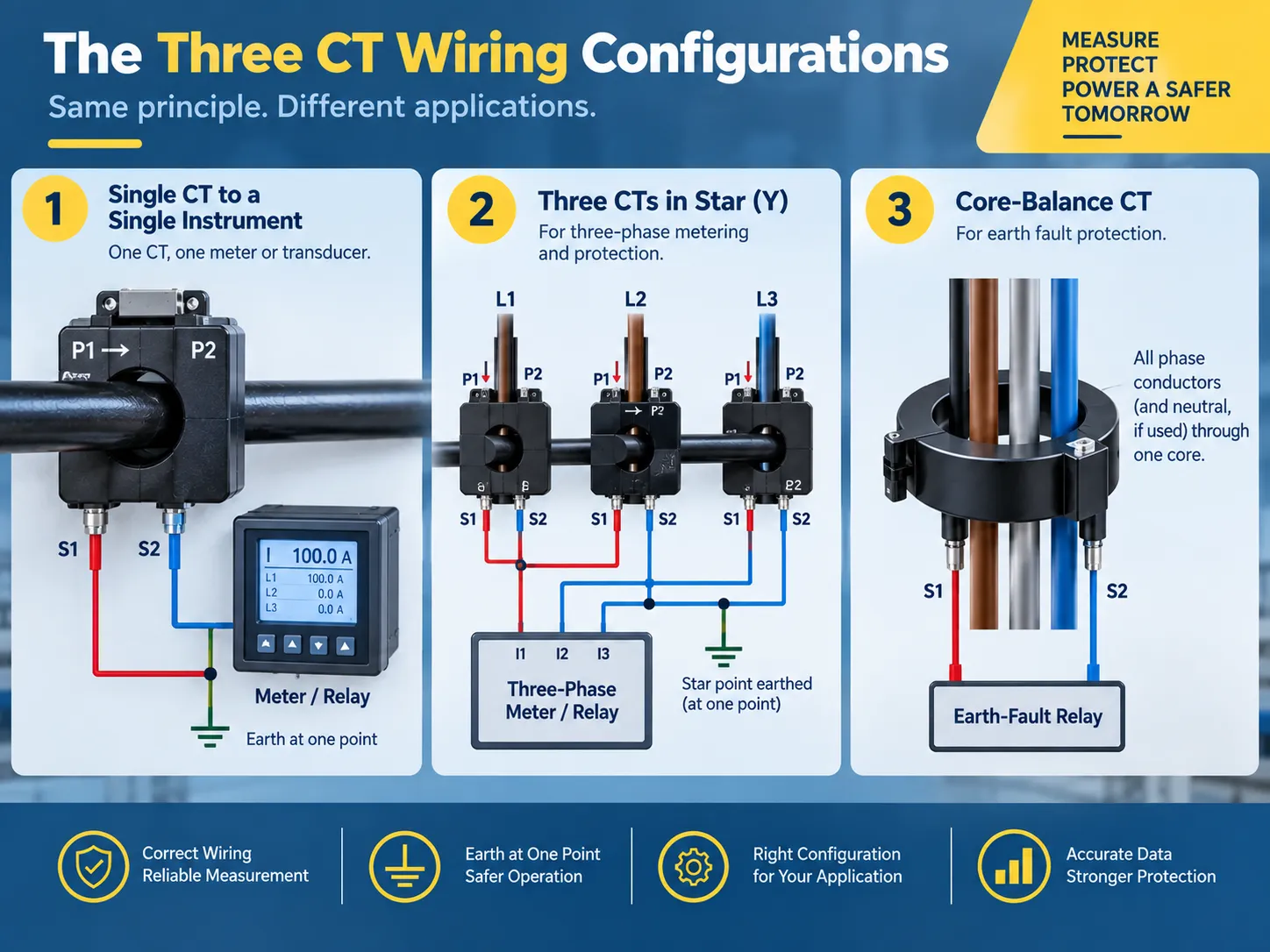
Три конфигурации проводки, которые вы на самом деле будете использовать
Почти каждая установка CT делится на три типа конфигурации:
- Один CT используется в сочетании с одним прибором. Один CT с измерителем или датчиком: S1 подключается к S1 прибора, а S2 подключается к S2 прибора, в то время как вторичная сторона заземляется в одном месте (обычно на панели прибора). Это стандартный способ использования для выделенной панели питания или мониторинга тока двигателя. Та же процедура повторяется три раза в случае трехфазного, четырехпроводного учета.
- Использование трех CT в Y-конфигурации для трехфазного учета и защиты. Здесь все три провода S1 подключены к соответствующему входу тока прибора, в то время как все три провода S2 соединены в одну звезду. Эта звезда - это точка, где вторичная сторона заземляется. Звездная конфигурация используется как стандартная конфигурация для трехфазных счетчиков энергии и счетчиков мощности, так как она обеспечивает точное копирование фазных токов и также предоставляет путь для токовых дисбалансов.
- Трансформатор с балансировкой сердечника используется для обнаружения земляных коротких замыканий. В этом случае все три фазных проводника (и нейтраль, в зависимости от применения) проходят через один сердечник трансформатора. В нормальном состоянии векторная сумма токов равна нулю, и, следовательно, вторичная обмотка трансформатора показывает ноль; любое земляное короткое замыкание приводит к тому, что некоторый ток возвращается через землю вместо нейтрали и создает остаточный сигнал, который обнаруживается реле защиты от земляных коротких замыканий. Проводка в этой конфигурации менее сложная (только два вторичных провода идут к реле), но необходимо соблюдать определенные физические правила: никакие другие провода не могут проходить через сердечник, и экран или броня кабеля не могут создавать параллельный путь, который отменяет остаточный ток.
Если тот же трансформатор должен предоставлять данные как для счетчика, так и для реле защиты, то два нагрузки соединяются последовательно (сначала счетчик, затем реле, или с использованием альтернативных сердечников, если у трансформатора есть несколько вторичных обмоток) и не параллельно или с неиспользуемыми сердечниками. Философия защиты, лежащая в основе остаточных соединений, объясняется далее в нашем основах защиты от земляных замыканий руководстве.
Схема подключения трансформатора, объясненная
Необходимо читать схему подключения трансформатора, начиная с первичной стороны и заканчивая прибором. Вот пример того, как будет выглядеть установка трехфазного учета, представленная в виде схемы:
| От | Чтобы | Проводник |
|---|---|---|
| Phase A conductor (source side) | CT-A P1 | Primary circuit — not CT wiring |
| CT-A S1 | Meter current input IA (S1) | 2.5-4 mm² copper, 600 V rated |
| CT-A S2 | Star point | Same size as S1 |
| CT-B S1 | Meter current input IB (S1) | Same size |
| CT-B S2 | Star point | Same size |
| CT-C S1 | Meter current input IC (S1) | Same size |
| CT-C S2 | Star point | Same size |
| Star point | Earth (one point only) | Grounding conductor per local code |
| Each S1/S2 pair | Shorting/test terminal block | Installed between CT and instrument |
If your project has a supplied wiring diagram, it should be used as the primary source document. However, all of the following three conventions should be used to verify it before you finalize the installation: use of S1 to S1 pairing, use of a single earth point, and presence of a shorting mechanism in the circuit. Any discrepancies in these three aspects can lead to improper commissioning and create unsafe conditions.
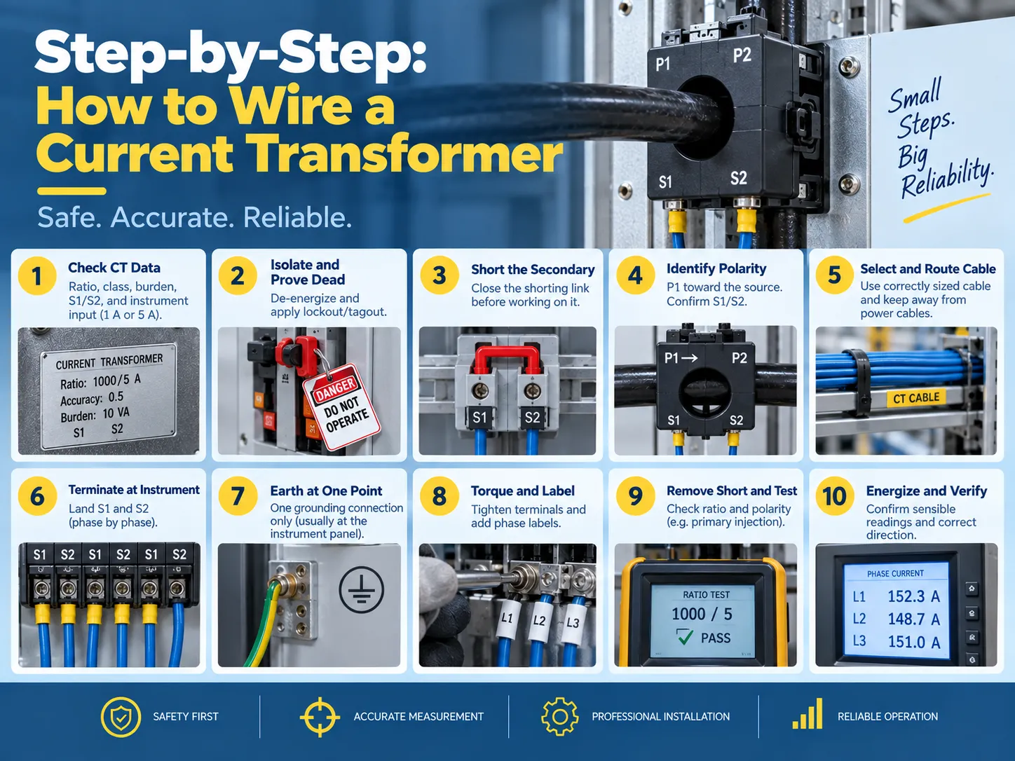
Step-by-step: how to wire a current transformer
- The first step is to verify the CT data and check the instrument demands. Check the nameplate for the ratio, accuracy rating, burden (VA), and polarity markings. Confirm the input rating of the instrument (1 A or 5 A) is consistent with the CT secondary because if a 5 A CT is connected to a 1 A input, the instrument will read inaccurately by a factor of five and may saturate the input.
- The device must be isolated, followed by the verification of the dead condition. The primary circuit must be de-powered, and proper lockout/tagout measures must be applied. It is important to remember that “even if the primary circuit has been isolated, there may still be a live CT secondary that is energized from another source” and hence it is important to consider every CT circuit live until proven otherwise.
- The next step is to short the secondary circuit. The shorting link on the testing terminal block needs to be closed or a proper shorting device may be used to connect S1 and S2. This procedure eliminates the danger of CT failure.
- The next step is to find the polarity that involves locating the points P1 and P2 of the primary as well as S2 and S1 for the secondary. It is essential to confirm that the primary orientation (where P1 points toward the source) and the physical arrangement matches the diagram.
- Select the proper secondary cable. Copper conductors of the appropriate size need to be used for both the burden and run length (standard 2.5 mm², 600 volts) with the goal of avoiding running power conductors in the sheath while achieving all three phases.
- Termination needs to happen at the instrument with S1 in the S1 (polarity) input on the instrument and S2 on the second input.
- Ensure that there is a grounding at only one point, typically at either the instrument or relay panel.
- Check the terminals for torque settings according to the manufacturer and apply labels to the phases including the ratio label.
- The shorting link must be removed before testing commences with the verification of the ratio and polarity.
- Turn the energizing circuit on so the circuit is reading correctly on the instrument with all three phases being noted at the current reading.
Burden and cable sizing: the calculation most installers skip
Current transformers (CTs) have a rated burden above which they will not be accurate. The burden total includes all devices connected to the secondary and the resistance of the secondary wiring:
- Instrument burden: this is the VA burden (or ohmic) specified by the manufacturer of the meter or relay. It can vary by instrument type, but is generally in the range of 0.2-1 VA per current input for modern electronic instruments and higher burdens for older electromechanical relays.
- Wiring burden: the wiring resistance is calculated as follows: 2 x one-way length x resistance per meter (for example, the resistance for 2.5 mm2 copper wiring is approximately 7.4 ohm/km), times the square of the secondary current. Depending on the run length, it is not uncommon for the instrument burden to be exceeded simply due to wiring burden.
- Connection burden: the resistance across the terminals and test blocks is generally small, but if the wiring total is close to the CT burden, this value should be included.
If the total burden exceeds the rating of the CT, it cannot provide accurate readings and may saturate during fault currents – which is when protection is needed most. Possible remedies include a shorter cable run, a larger conductor, using a lower-burden instrument, or buying a CT with a higher VA rating.
The accuracy classes themselves — 0.5 and 1 for metering, 5P and 10P for protection — are explained in our transformer accuracy classes guide.
And the ratio-selection logic for a given installation, from load current and fault level to the final nameplate choice, is covered in our current transformer ratio selection статье.
Testing and verification
Three tests are used to ensure that a CT is installed correctly before it is allowed to carry load:
| Испытание | What it proves | Метод |
|---|---|---|
| Ratio test | The CT produces the expected secondary current for a known primary current | Primary injection at a fraction of rated current, or a secondary-voltage method for large CTs |
| Polarity test | S1 truly corresponds to P1 and the instrument reads forward power correctly | DC pulse or primary injection with a polarity-sensitive instrument |
| Insulation and continuity | No shorted or open secondary conductors, and adequate insulation to earth | Insulation resistance and continuity checks before energization |
Post-energization verification is equally important because you should compare the readings of the CT with a reading from a clamp meter on the primary side, verify that the readings are consistent across all three phases, and confirm that the earth-fault circuits register zero residuals on a healthy feeder.Where the CT is part of a protection scheme, that coordination — and the grounding references it depends on — is the subject of our основах заземления трансформаторов руководстве.
Safety rules, and the mistakes that damage equipment
The secondaries of current transformers only flow small amounts of current at low voltages—until something goes wrong. The following are mandatory guidelines for dealing with current transformer circuits:
- Never open the current transformer circuit secondaries while the primary circuit is energized. The current transformer will attempt to generate very high voltages (hundreds or thousands of volts) across the secondary terminals when it is open, leading to an extreme overvoltage situation, core saturation, overheating, and potentially explosion and fire.
- Ground the current transformer secondary only at one point. Connecting the ground at two points will cause unnecessary current to circulate through the ground contributing to an incorrect measurement and potentially causing an unnecessary trip of protection equipment.
- Avoid installing a switch or fuse in the current transformer circuit that is not a shorting type of test block. Standard circuits may fail open which creates the same condition as an open circuit.
- Do not leave spare current transformer cores open. Short the unused coils and note them on the drawing, or future technicians may be incorrectly leading service personnel to assume that they are open circuits.
- Be sure to observe proper polarity at each connection. The S1-to-S1 and P1-to-source connections are not arbitrary conventions that may be changed later.
- Keep current transformer wires away from power and variable frequency drive (VFD) cables, and do not pass the current transformer around just a single part of the conductor in a core balance scheme.
Two other practical points to remember are that a current transformer must be hooked up with the instrument input rating matching the transformer’s secondary rating (either 1A or 5A) and that the primary conductor must pass through the window in one direction only. Passing a bar or cable back through the core backwards will reverse the effective polarity of the current transformer.For meters that must be removed for calibration, the test block should be the type that automatically shorts the CT when the instrument is unplugged; the wiring practices around metering and instrument transformers are also covered in our current transformer installation guide.
Часто задаваемые вопросы
What are the disadvantages of using a current transformer?
There are several drawbacks; having an open-circuit secondary is dangerous since it creates the possibility of serious injury; calculation of the connected load must be done correctly, or else inaccurate readings will be produced; incorrect polarity can result not only in inaccurate readings but also in malfunctioning protection devices; there is a small phase shift introduced by the CT that results in a slight inaccuracy in measurements; added expense and panel space; proper sizing is necessary, otherwise, the CT will saturate during a fault condition. Although modern electronic meters do reduce some of the problems associated with these drawbacks, all of them cannot be eliminated.
How are current transformers wired?
To connect the primary conductor through the CT there is P1 (the source side) and P2 (the load side) or the line is passed through the bar / window. The secondary side will be S1 and S2 with S1 corresponding to P1. The S1 and S2 will lead to either a meter, relay, or transducer directly for a single CT or in a star configuration for three-phase metering (three S1s to the meter and three S2s coupled to one grounded star point, etc.). There is a shorting/test terminal block mounted at the juncture of the CT and the instrument.
Does it matter which wire goes where on a transformer?
For any transformer it does; however, CTs have unique requirements. This is due to the leads having a specific polarity (i.e., S1 correlating to P1). By reversing these two leads, it causes current to flow in the opposite direction creating inaccurate power readings along with the possibility of malfunctioning protection devices. This is applicable in both transformers with respect to the primary and secondary leads.
How do you connect an electrical transformer?
In the case of an instrument transformer such as a CT: verify the ratio and the burden, isolate the transformer and prove it to be dead, short out the secondary side, identify which lead corresponds to P1 and which lead corresponds to S1; connect the correctly sized secondary cable such that S1 and S2 lead to the instrument’s respective inputs, ground the secondary at one point, label and torque the connection, remove the ground; and finally inject a known standard into the system to verify polarity and ratio. The process for connecting a power transformer differs from this procedure but still requires the individual to verify ratings, polarity, grounding, and testing before energizing load.
Ссылки
- IEEE — C57.13, Standard Requirements for Instrument Transformers
- IEC — 61869 Series, Instrument Transformers
- NFPA — National Electrical Code (Instrument Transformer Circuits)
- NETA — Acceptance Testing Specifications for Electrical Power Equipment
Заключение
The installation of the current transformer carries a lot of weight although it may seem like an unimportant task. The function of the current transformer is to reduce the amount of primary current flowing through the wire to a safe reading for the meter or relay. Therefore, you can see how important this task is in the long run. For the primary wire (P1) you will have to run wire to the source while the secondary wire (S1) will run from the current transformer to the meter or relay. If you are wiring three-phase meters, the circuits must be wired in a star pattern and grounded at a single point to earth. Use a core-balance CT for residual currents; make sure you size the secondary wire appropriately according to the burden load. Always use a test block to short out the circuit before energizing it and never break the circuit as long as current is flowing through the primary side. Make sure that you check the readings first using primary injection and then record the ratio on the sheet for future reference.