


يتم أحيانًا الخلط بين معدات التبديل ولوحة التبديل على أنها واحدة ونفس الشيء؛ يمكن رؤية ذلك في مستندات العقود، وفي الإرساليات عبر البريد الإلكتروني وفي بعض المخططات الخطية المحددة. بينما تخدم الكيانين غرضًا مشتركًا، إلا أنهما في الواقع فئتان متميزتان لهما معايير UL الخاصة بهما، وعمليات التصنيع، والأسعار؛ لذلك، لا ينبغي الخلط بينهما بناءً على الحجم فقط. يصبح الفرق بين هاتين الفئتين واضحًا بعد أسابيع أو أشهر أو حتى سنوات من اكتمال التركيب؛ في بعض الأحيان يكون ذلك بسبب تلقي رسومات تعيد تصميم المعدات المثبتة، وفي أوقات أخرى يكون بسبب تلقي حسابات تتعلق بالتيار القصير لا تتطابق مع تصنيف المعدات، وفي بعض الحالات، يكون ذلك بسبب إدراك موظفي الصيانة أنه من أجل إجراء الصيانة على المغذي، يجب إيقاف تشغيل التجميع بالكامل.
بشكل أساسي، تعتبر لوحة التبديل المتوافقة مع UL 891 منتجًا ‘مغلق الواجهة’ يتم تزويده بالطاقة منخفضة الجهد ويوزع الجهد المنخفض إلى الأجهزة الرئيسية والمغذيات باستخدام قواطع دوائر ذات حالة مصبوبة أو قواطع دوائر معزولة (على أساس فردي أو جماعي). من ناحية أخرى، تعتبر معدات التبديل المتوافقة مع UL 1558 قاطع دوائر منخفض الجهد مع غلاف معدني أكثر وستتضمن قواطع دوائر متوافقة مع UL 1066 لتصنيف التيار القصير وغلافات الحافلات والقواطع والكابلات. كلا النوعين مخصصان للاستخدام عند أقل من 1000 فولت، وعادة ما تبدو كلا النوعين متشابهة حيث تم تصميم كلاهما لتوزيع الطاقة منخفضة الجهد؛ ومع ذلك، ستكون معدات التبديل قادرة على تحمل الأعطال والاستمرار في العمل بفضل تصنيفها لتحمل الأعطال. يجب عليك اختيار لوحة التبديل عندما تكون المال والمساحة عوامل؛ عندما تحتاج إلى إجراء صيانة على النظام دون إيقاف تشغيل النظام، اختر معدات التبديل. نفس المبدأ ينطبق على أنواع معدات التبديل ذات الغلاف المعدني التي تتوافق مع معايير IEEE. تقدم شركة Subian Electric كلا النمطين من المعدات (معدات التبديل المفتوحة ومعدات التبديل منخفضة الجهد).
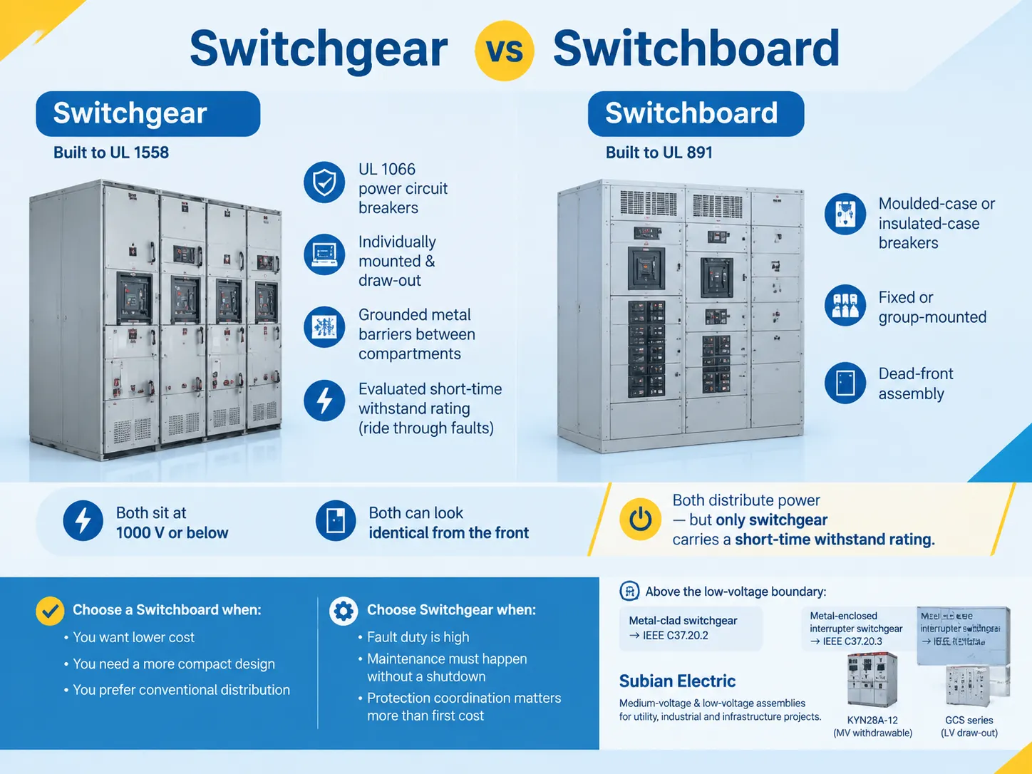
الإجابة القصيرة، ولماذا لا يتعلق الأمر بالحجم
من الصحيح أن المرء يمكن أن يقول إن لوحات التبديل هي المعدات الأقل تكلفة من بين المجموعتين بينما معدات التبديل هي المعدات الأكثر تكلفة والأكبر حجمًا؛ ومع ذلك، فإن هذا ليس كافيًا لاتخاذ قرار بين العنصرين. يمكن أن تحتوي لوحة التبديل على تصنيف يصل إلى 1000 فولت وتكون قادرة على التعامل مع تيار قصير متاح يصل إلى 200,000 أمبير، بينما قد تحتوي سلسلة معدات التبديل على تصنيفات لن تحتاجها مرافق الشركات المتوسطة الحجم أبدًا.
العامل المميز الحقيقي بين العنصرين هو أداؤهما أثناء حدوث العطل والصيانة. من المفترض أن يقوم اللوحة الكهربائية بقطع العطل عن طريق جعل قواطعها تنفصل تقريبًا على الفور. بالمقابل، يتم تصنيع معدات التبديل لتحمل العطل لفترة محددة، والتي عادة ما تكون 30 دورة، وتساعد في إزالة العطل في الأسفل بواسطة جهاز قريب حتى بينما يبقى المفتاح الرئيسي مغلقًا وتستمر المعدات الأخرى في العمل.
تتبع جميع نقاط الاختلاف الأخرى هذه النقطة، بما في ذلك تقسيم الغرف، ووسائل التأريض المستخدمة، وآلية السحب، والمساحة داخل المحطة الفرعية، وقواعد الوصول والسعر. إذا كان من الممكن إيقاف تشغيل المعدات للصيانة وقد يتسبب عطل محلي في قطع الطاقة عن المنشأة بأكملها دون التأثير على التشغيل، يمكن اقتراح استخدام اللوحة الكهربائية كأفضل حل. إذا كنت بحاجة إلى ضمان التشغيل المستمر، فإن السعر الأعلى لمعدات التبديل يعني أنك تستثمر في خدمة غير منقطعة.
ما هي معدات التبديل
تشير معدات التبديل منخفضة الجهد في أمريكا الشمالية إلى معدات قواطع الدائرة الكهربائية المعدنية المغلقة منخفضة الجهد، والتي تخضع لمعايير UL 1558 ومتصلة بمعايير البناء ANSI/IEEE C37.20.1 ومعايير اختبار ANSI C37.51. ينطبق هذا المعيار على المعدات المصنفة تحت 1,000 فولت AC اسمي. تم إضافة متطلبات جديدة لمعدات التبديل متعددة المصادر أيضًا في الطبعة السادسة من UL 1558 التي صدرت في شهر أبريل 2025، حيث تم إجراء أول تعديل في يونيو 2026.
ومع ذلك، فإن القاطع يحدد الفئة بدلاً من الجهد نفسه. تتكون معدات التبديل من قواطع دوائر منخفضة الجهد، تم اختبارها وفقًا لمعايير UL 1066، والتي تصنف 100% ويمكن أن تعمل في الحاوية دون صيانة وتقدم تشغيلًا كاملًا عن بُعد في حالات الفشل الاستثنائية وقد تمر عبر أعطال لمدة 30 دورة متتالية. عادةً ما يتم تثبيت القواطع بشكل منفصل وتكون بتصاميم سحب.
البناء نفسه يعكس نموذج الصيانة. يتم فصل الغرف عن بعضها البعض بواسطة تجميع معدني مؤرض وكل قاطع معزول عن الآخرين. كما يتم فصل غرف الكابلات والحافلات عن بعضها البعض. إن استخدام الحواجز يقضي على انتشار الأعطال من كابينة إلى أخرى مما يخلق ضرورة لتصميم مساحة أعمق لمعدات التبديل مقارنةً بأنواع أخرى من اللوحات الكهربائية.
عادةً ما تتكون أي مجموعة من معدات التبديل من معدات الخدمة الرئيسية، وتوزيع التغذية الحرجة، وترتيبات متعددة المصادر والرئيسية-الرئيسية، ونقاط توصيل المولدات، والمرحل الحماية، ومعدات القياس، وأجهزة الاتصال والمراقبة، وأكثر فأكثر، عناصر تقليل وميض القوس. يسمح البناء في النهاية للأداء بتحقيق أداء المعدات بدلاً من مجرد افتراض خصائصها. يتم تغطية تعريفات مستوى التجميع للبناءات المعدنية المغلقة في ملاحظتنا حول معدات التبديل المعدنية المغلقة.
ما هي اللوحة الكهربائية
لوحة التوزيع، كما تُعرف في أمريكا الشمالية، هي مجموعة أمامية ميتة مُصممة وفقًا لمعيار UL 891. وفقًا لحلول UL، يُعتبر UL 891 هو المعيار الأكثر استخدامًا فيما يتعلق بتركيب لوحات التوزيع الأمامية الميتة في أمريكا الشمالية. المعيار المشار إليه ينطبق على لوحات التوزيع التي لديها تصنيفات جهد لا تزيد عن 1000 فولت. من حيث قدرة تيار العطل، يمكن أن تصل إلى 200,000 أمبير RMS. ومع ذلك، كل لوحة توزيع لها تصنيفها الخاص، وأيضًا العلامة التي تتوافق مع تصنيفها. في مراجعة مارس 2025، كانت هناك متطلبات إضافية أو محدثة تتعلق بلوحات التوزيع متعددة المصادر، وتبريد الهواء القسري، والدورات الطارئة، ومعدات الخدمة.
السمة الرئيسية للسلامة هنا هي جانب الجبهة الميتة، مما يعني أنه لا يوجد وصول إلى الأجزاء الحية من الجانب الأمامي للمعدات تحت ظروف التشغيل القياسية. ومع ذلك، لا ينص UL 891 على متطلبات تقسيم الأجهزة المختلفة. يتم تجميع القواطع التي يمكن العثور عليها في لوحة التوزيع معًا، بينما عادةً ما تحتوي المعدات الواقية على قواطع مصبوبة وفقًا لمعايير UL 489، أو قواطع عازلة، أو مفاتيح UL 98 التي تأتي مع مصاهر UL 248. القواطع المصبوبة هي معدات لا يمكن إصلاحها. وهذا يعني، مع ذلك، أنه بينما تكون المعدات قيد التشغيل، عادةً ما تكون مصنفة عند 80% من التصنيف القياسي ما لم يتم ذكر معلمة أخرى.
هناك استنتاجان مهمان ينشأان من هذا النوع من المعدات. الأول هو أن التجميعات الأمامية الميتة عادةً ما تكون أصغر من معدات التوزيع التقليدية للقوة المقابلة، حيث يسمح التركيب الجماعي بتثبيت المزيد من الطاقة لكل منطقة. بالإضافة إلى ذلك، لا يعني UL 891 أن لوحات التوزيع قد تحتوي أيضًا على تصنيفات قصيرة المدى تمكنها من استخدامها في حالات العطل.
محتويات لوحات التوزيع أيضًا عديدة: قواطع رئيسية معزولة أو مصبوبة، بالإضافة إلى مفاتيح رئيسية قابلة للصهر، وأطراف رئيسية، وقواطع تغذية، وقواطع قابلة للصهر، وموصلات نحاسية أو ألمنيوم، وموصلات محايدة وأرضية، ونظام عد، ونظام حماية من الارتفاعات، وقسم سحب الكابلات، ونظام مراقبة، مرتبة في نظام مستقل.
كيف تعمل معًا في نظام توزيع واحد
في العديد من المنظمات، لا تتنافس معدات التوزيع ولوحات التوزيع على نفس المكان. يتم وضع النظامين بشكل مختلف داخل المشروع، حيث من الشائع أن تستخدم المشاريع الكبيرة كلاهما. تمر عملية التقطير من شركة المرافق عبر أقوى المعدات، وتوزع الكهرباء إلى الأجهزة الأقل قوة. مزود الخدمة أو المحول الكهربائي هو المصدر الرئيسي للطاقة للمعدات الكهربائية. سيكون المستوى التالي من دائرة توزيع الطاقة أقل، يليه مستوى الدوائر المتفرعة. في الواقع، التمييز بين المستوى الأول والثاني هو ما يجعل تحديد ما إذا كان يجب استخدام معدات UL 891 أو UL 1558.
هناك مشكلة خطيرة أخرى في التسمية بسببها يمكن أن يرتكب المشترون أخطاء في عملية الشراء. على سبيل المثال، كانت ممارسة شائعة في الأسواق المعتمدة على IEC الإشارة إلى أنظمة التوزيع الرئيسية الكبيرة باسم “معدات التبديل”، وهو مصطلح أوسع يشمل المحولات وخطوط الطاقة الأخرى. في مثل هذه الحالات، يستخدم المشترون مصطلح “معدات التبديل” حتى لو كان ينبغي عليهم شراء لوحة توزيع UL 891. قد تحدث الحالة المعاكسة أيضًا عندما يطلب المشترون “لوحة توزيع” في حالة تتطلب استخدام قواطع دوائر UL 1558 القابلة للسحب. عند التعامل مع مثل هذه المشاريع في الخارج، من المهم تحديد نوع المشروع وفقًا للمعايير المستخدمة، بدلاً من وفقًا للكلمة الشائعة.
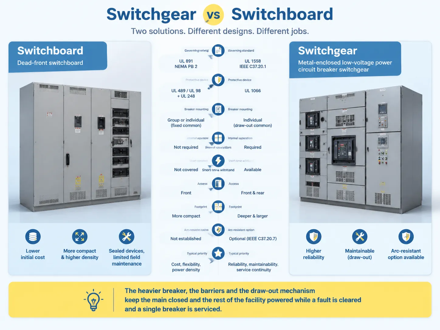
معدات التبديل مقابل لوحة التوزيع: جنبًا إلى جنب
| العامل | لوحة التوزيع | معدات التبديل |
|---|---|---|
| المعيار الحاكم | UL 891؛ NEMA PB 2 إرث | UL 1558؛ IEEE/ANSI C37.20.1؛ ANSI C37.51 |
| وصف المنتج | لوحة توزيع ذات واجهة ميتة | معدات قواطع دوائر الطاقة منخفضة الجهد محاطة بالمعادن |
| جهاز الحماية | قواطع UL 489 ذات الحالة المصبوبة أو المعزولة؛ مفاتيح UL 98 مع مصاهر UL 248 | قواطع دوائر الطاقة منخفضة الجهد UL 1066 |
| تركيب القواطع | مثبتة في مجموعة أو مثبتة بشكل فردي، غالبًا ما تكون ثابتة | عادة ما تكون مثبتة بشكل فردي وقابلة للسحب |
| الفصل الداخلي | غير مطلوب بين الأجهزة | الحواجز مطلوبة بين القواطع، والحافلات، وأقسام الكابلات |
| التحمل لفترة قصيرة | غير مشمولة بـ UL 891 | متاحة في تكوينات تم تقييمها |
| سلوك العطل | الأجهزة تنفصل دون تأخير متعمد عند حدوث عطل كبير | يمكنها تحمل العمل خلال عطل، عادة حتى 30 دورة |
| نهج الصيانة | أجهزة محكمة الغلق، صيانة ميدانية محدودة | قواطع قابلة للسحب يمكن صيانتها مع تشغيل الحافلة |
| الوصول | وصول أمامي قياسي | وصول أمامي وخلفي قياسي |
| البصمة | عادة ما تكون أكثر إحكامًا، وكثافة طاقة أعلى | عادة ما تكون أعمق وأكبر |
| خيار مقاوم للشرر | Not established by the UL 891 listing | Optional, separately specified and evaluated per IEEE C37.20.7 |
| Typical priority | Installed cost, flexibility, power density | Reliability, maintainability, coordination, service continuity |
By reading alongside the short-time withstand row, the rest of the table makes sense. The heavier circuit breaker, the barriers, and the withdraw mechanism are all designed to do one thing: keep the main circuit closed and the facility energized while a fault downstream is cleared and one circuit breaker is maintained.A representative low-voltage assembly built on that logic is described in our GCS low voltage draw-out switchgear.
The Three Types of Switchgear, and the Three Levels of Switchboard
When it comes to classifying equipment, the next logical step will be enquiring what construction class is being dealt with. As it happens, the construction class criteria are clear and straightforward. There are three construction classes for the switchgear, as defined by the National Electrical Manufacturers Association. The rest, including compact switchgear, arc-resistant design, gas-insulated equipment is just a modified version within the basic classes.
| النوع | معيار | نطاق الجهد | Distinguishing feature |
|---|---|---|---|
| معدات قواطع دوائر الطاقة منخفضة الجهد محاطة بالمعادن | IEEE C37.20.1 / UL 1558 | Up to 1000 V AC nominal | Compartmentalised LV assembly with UL 1066 draw-out breakers |
| Metal-clad switchgear | IEEE C37.20.2 | 5 kV to 38 kV, extended to 48.3 kV | Draw-out breakers, grounded metal barriers on all four compartments, automatic shutters, mechanical interlocks |
| Metal-enclosed interrupter switchgear | IEEE C37.20.3 | Above 1 kV up to 48.3 kV | Interrupter switches with power fuses; performance-based rather than structurally prescriptive |
The importance of the metal-clad clause must be understood as the standard is more prescriptive than aspirational. Thus, IEEE C37.20.2 realizes that the breaker, main bus, cable, and low-voltage compartments need to be separated by grounded metal barriers with no intentional openings between them; that the interrupting device is removable with connected, test, and disconnected positions; that there are automatic shutters protecting the primary stabs once the breaker is taken out; and that there are mechanical interlocks that prevent any closed breaker from being racked out or a wrong positioned breaker from being closed. The continuous ratings of the main bus generally fall within the ranges of 1200 A, 2000 A, 3000 A, and 4000 A.
Meanwhile, IEEE C37.20.3 does not share the same approach. Unlike the previous standards, this one governs the metal-enclosed assemblies in which switches interrupt load current inside the grounded enclosure using interrupt switches and fuses instead of the draw-out breakers. Metal-enclosed switchgear is lighter, more compact, and less expensive thus providing a desirable solution for feeders operating rarely while being below the fault levels consistent with draw-out breakers. One of the popular warnings within the industry is relevant for the situation with metal-clad switchgear since it is true that all metal-clad switchgear enables one type of metal-enclosed switchgear yet one cannot say vice versa without proving o the compliance with all previous statements.
With respect to cases when arc resistance is called for it should be emphasized that arc resistance would be mentioned in a specific way and that would be covered by IEEE C37.20.7 which refers to arc-resistant switchgear producing voltage of up to 52 kV and defining access ratings, such as: Type 1 serves only the people working in front of it while Type 2 facilitates the safety of people working in the front, behind, and on either side of it. It is worth mentioning that the arc-resistant construction is becoming widely used in data centers and industries in modern times and should be checked and verified independently of the type of equipment used to create the construction.
The rules regarding levels at the switchboard side are going in the opposite direction since the levels depend on their position in the system and not on their construction classification. As for UL 891, those switchboards are used for main and feeder distribution. UL 67 panelboards, rated within 1200 A, have the purpose of distributing the branch circuits while being mounted onto the wall. The commonly used sequence illustrates the power generating plant and transformer powering the switchboard which is further linked to the panel boards.Buyers comparing switchboards against legacy brand-name line-ups often arrive through a specific manufacturer’s catalogue; Siemens switchgear naming and positioning is a useful example of how one vendor organises an overlapping range, covered in our notes on Siemens switchgear.
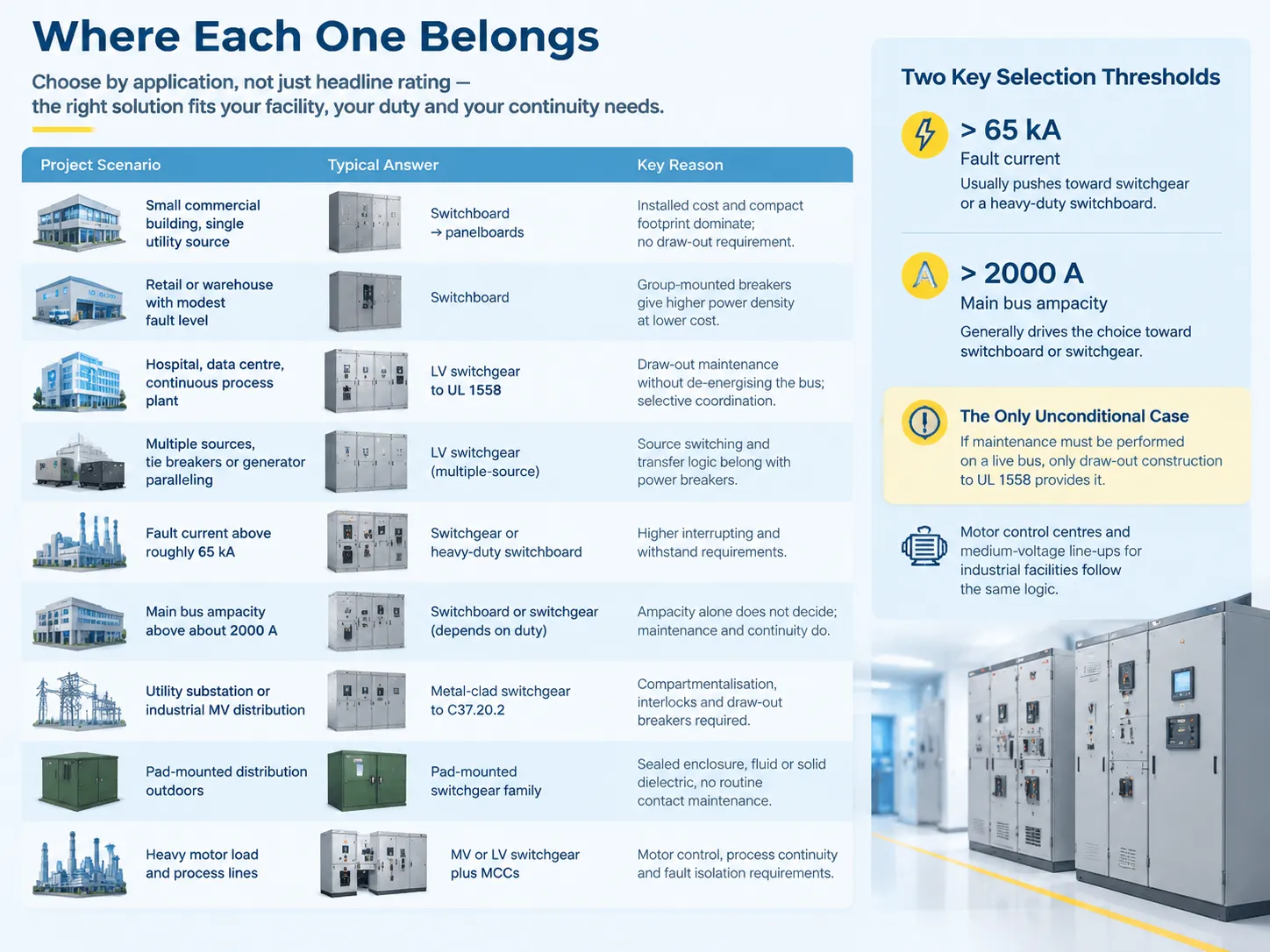
Where Each One Belongs
Deciding by application is more reliable than deciding by headline rating, because the applications cluster naturally around the maintenance and continuity requirements — and in practice they land in the same building types, from industrial manufacturing facilities to hospitals and data halls.
| Project scenario | Typical answer | السبب |
|---|---|---|
| Small commercial building, single utility source | Switchboard feeding panelboards | Installed cost and compact footprint dominate; no draw-out requirement |
| Retail or warehouse with modest fault level | لوحة التوزيع | Group-mounted breakers give higher power density at lower cost |
| Hospital, data centre, continuous process plant | LV switchgear to UL 1558 | Draw-out maintenance without de-energising the bus; selective coordination |
| Facility with multiple sources, tie breakers or generator paralleling | LV switchgear, multiple-source configuration | Both UL 891 and UL 1558 now address multiple-source arrangements, but source switching and transfer logic belong with power breakers |
| Fault current above roughly 65 kA | Switchgear or heavy-duty switchboard | Higher interrupting and withstand requirements push toward heavier construction |
| Main bus ampacity above about 2000 A | Switchboard or switchgear depending on duty | Ampacity alone does not decide; maintenance and continuity do |
| Utility substation or industrial MV distribution | Metal-clad switchgear to C37.20.2 | Compartmentalisation, interlocks and draw-out breakers required |
| MV feeder that switches infrequently | Metal-enclosed interrupter switchgear to C37.20.3 | Lower cost and smaller footprint suit the duty cycle |
| Pad-mounted distribution outdoors | Pad-mounted switchgear family | Sealed enclosure, fluid or solid dielectric, no routine contact maintenance |
| Industrial plant with heavy motor load and process lines | MV or LV switchgear plus MCCs | Motor control, process continuity and fault isolation requirements |
There are typically two selection limits not only in a way industry sometimes mentions that it’d be good to name them carefully, one of them being that it is not a standard itself. The point is that any projects where current flows in excess of around 65 kA normally find themselves utilizing the switchgear as well as heavy-duty switchboards instead of conventional ones. Moreover, if the choice of the bus is around 2000 A, you can bet it is either switchboard or switchgear and turned down anything that lies in the area of a panelboard.Motor control centres and medium-voltage line-ups for industrial facilities are built to the same logic — an example of the MV and LV assemblies used in that combination is described in our KYN28A-12 withdrawable AC metal-enclosed switchgear.
How to Specify the Right One
The following specifications are presented according to the sequence in which the information on them is finally collected. The commonest way for projects to procure the wrong model is by jumping from the equipment specification to the category, before the fault study has been done.
- Determine the existing fault current. It is a project requirement to conduct a short-circuit analysis. An equipment’s short-circuit rating must match or exceed the fault current at the equipment terminals, as per NEC 408.6. Thus, without this analysis, it is impossible to make reliable decisions regarding any downstream ratings.
- Indicate the equipment designations according to their standard numbers. For example, indicate “dead-front switchboard per UL 891” or “metal-enclosed low-voltage power circuit breaker switchgear per UL 1558 and IEEE C37.20.1”. Naming the standards eliminates ambiguity of the term “switchgear”.
- Define the maintenance approach even before pricing it out. Ask whether it will be possible to service any feeder with the rest of the site being energized. If the answer is “yes”, then the requirement becomes draw-out design, and it can no longer be reversed beyond this point without completely replacing the assembly.
- Confirm the short-time withstand criteria separately. It is important to note that UL 891 does not provide any short-time withstand current ratings, which means that if a design presumes a withstand period, this information should be explicitly mentioned in the UL 1558 specification. Do not assume anything by looking at switchboard quotations.
- Make sure the device class and the coordination study stay together. Selective coordination is possible in certain installations on both platforms, but power circuit breakers provide wider possibilities in terms of settings and delay. In case the design depends upon coordination at high fault levels, the class of the circuit breaker and the study should be treated as a single deliverable.
- Specifically indicate the requirement for arc-resistant construction only if this requirement is present. Arc resistance testing is to be performed in compliance with IEEE C37.20.7, while UL 891 and
- UL 1558 do not include any requirements regarding the arc resistance testing. Indicate the type of the equipment access required, Type 1 or Type 2, and ask for the testing results.
- Coordinate the layout of the entire room rather than only the equipment. Room requirements include space for equipment access, entry direction for incoming cables, back distance, space required for ventilation of forced-ventilated designs, and room needed to remove and reload the circuit breaker.
- Plan procurement in accordance with realistic lead times. Lead times for low-voltage draw-out switchgear reached 70-80 weeks in early 2024, which means that procurement decisions for equipment with long delivery times must be finalized at the schematic design stage. Treating switchgear as a last-minute purchase is how projects lose the commissioning window.
A deceptively common issue in manufacturing needs clearing up. It is when there is a specification for “switchgear” in the plans, but the buyer has instead brought in UL 891 switchboards at lower cost. The one-line diagram has been unaffected. However, the installation cannot achieve all the required ratings and thus operation of the plant can be jeopardized and the problem can go unnoticed until the failure occurs. In case switchgear is needed, it will be best if the plans indicate so and provide relevant standards.
الأسئلة الشائعة
What is another name for switchgear?
The official term is switchgear assembly – switchgear in IEEE C37.100.1 is outlined as term that encompasses switchgear assembly which includes switching, interrupting and controlling, metering, protective and regulating devices and enclosing structures. Similar concept in IEC market is an assembly of devices, hence the word has broader meaning there. For medium voltage construction terms are, respectively: metal-clad switchgear, metal-enclosed interrupter switchgear, compact switchgear related to IEEE C37.20.9. Old drawings of North America would refer to historical names of NEMA SG 3 and SG 5, which IEEE C37.20 has already replaced. At the facility itself the operators usually refer to switchgear simply as “gear”.
Is a breaker considered switchgear?
No. A circuit breaker is a component; switchgear is a component of the complete set. The importance of the distinction is that breakages and switchgear are governed individually, as in the case of UL1066 low voltage power circuit breaker and UL489 moulded case circuit breaker. After fitting, a breakage is part and parcel of a listed assembly, e.g. switchgear or switchboard assembly, and is subject to rating short circuit current capacity. Thus, the breaker class reflects the corresponding category of the installation: power circuit breaker refers to switchgear and case or insulated case circuit breaker refers to switchboard in every situation.
What are the three types of switchgear?
According to the American Institute of Electrical Engineers and the American National Standards Institute standards that provide coverage for construction within North America, there exist three classifications of machinery: namely, metal-enclosed switchgear circuitry that conforms with IEEE C37.20.1 and UL 1558 standards and has a capacity for operating at voltages of up to 1000V AC; metal-clad switchgear recognized as complying with IEEE C37.20.2 standards that operates with voltages within the range of 5kV through 38 kV and has a bus rating of 1200 A to 4000 A; finally, there is metal-enclosed switchgear that utilizes interrupter functions under standards of IEEE C37.20.3, which includes equipment rated higher than 1kV but within a voltage capacity of 48.3 kV. In addition, a third manner to categorize switchgear is by voltage class where switchgear machinery is divided into three groups: low voltage, medium voltage, and high voltage types.
What is the main purpose of a switchgear?
The goal is to provide controllability and survivability to the power system. This can be divided into four functions, which are often confused: constant carrying of the current without too much temperature rise, switching on and off circuits under load, interrupting the short-circuit and isolating the defective section, while keeping the rest of the system energized, and ensuring the safety of switching off so that people can work on the equipment. The construction features of the switchgear (barriers, draw-out mechanism, interlocks, shutters, withstand rating, etc.) are required for the last functions only. Hence, it is possible to use switchgear where unexpected outages are costly and where maintenance is carried out on the live system, while the use of switchboard works wherever it is not true.
المراجع
- IEEE Standards Association — C37.20.1, C37.20.2, C37.20.3, C37.20.7 and C37.100.1
- UL Solutions — UL 891 Switchboards, UL 1558 Switchgear, UL 67 Panelboards
- NEMA — PB 2 Deadfront Distribution Switchboards and SG series
- NFPA — NFPA 70 National Electrical Code, Article 408
- IEC — IEC 61439 and IEC 62271 series for assemblies and switchgear
- Eaton — application guidance on switchgear versus switchboards
- Schneider Electric — low-voltage distribution equipment documentation
- ANSI — C37.51 conformance test procedures
- Electrical Safety Foundation International — workplace electrical injury data
- OSHA — arc flash and electrical safety guidance
الخاتمة
Switchgear and Switchboards are two different types of electrical equipment. Each provides a unique function, has its own unique form factor, comes in many different types, etc. There are many different types of switchgear, but they are not the same as a switchboard.In order to ensure you are selecting the proper Switchgear or Switchboard, it is essential to follow the three rules outlined here. The first rule is to use the appropriate standard(s) when using either an Electrical Schematic Diagram or Architectural Document that specifies the switchgear or switchboard. Simply stating the common name of an item is not sufficient. The second principle states that you should select the maintenance program prior to determining the pricing of the equipment. A maintenance program cannot be added to the group type after pricing has been established, because the draw-out feature in a maintenance program, if not originally designed in, cannot be easily retrofitted. Finally, the third principle states that a short circuit analysis should be performed early in the project implementation process, as this analysis will help determine the type of switchgear or switchboard selections.