


Ein Stromwandler (CT) ist ein Gerät, das mit einem Mess-/Schutzsystem zur Messung großer Strommengen/Niveaus verwendet wird, die nicht direkt messbar sind; er wandelt Strom von 400, 1000 und 3000 A in einen nutzbaren Wert von 5 oder 1 A um. Diese Änderung erfolgt unter bestimmten Bedingungen, die vom CT-Gerät eingehalten werden müssen: Die Polarität muss korrekt sein, die Last muss genau sein, die sekundäre Verdrahtung sollte niemals einem offenen Stromkreis ausgesetzt werden, während Strom fließt. Das Handbuch enthält Spezifikationen zur Verdrahtungsverbindung von CTs mit Mess-, Relais- und Überwachungsgeräten, wie die Verdrahtung schrittweise eingerichtet werden sollte und wie dreiphasige Modelle verdrahtet werden sollten.
Falls der Primärstrom oder der mit dem Gerät verbundene Leiter durch den Transformator P1 und P2 geleitet wird, könnte die an den sekundären Anschlüssen P1 und P2 aufgezeichnete Messung aufgrund der Tatsache falsch sein, dass S1 in allen Fällen möglicherweise nicht mit P1 übereinstimmt, was zu einer Spannungsmessung des Stroms an den S1 S2-Verbindungen führt. Bei Verwendung eines einzelnen Transformators sind sowohl die S1- als auch die S2-Anschlüsse in Bezug auf alle dreiphasigen Verbindungen ungenutzt. Es besteht keine Anforderung für eine andere Verbindungsart, wenn ein einzelner CT verwendet wird, da es immer eine direkte Verbindung für die beiden von S1 und S2 sein wird. Im Falle einer dreiphasigen Verdrahtung sollte der Transformator mit der “Y”- oder Sternverbindungsart verbunden werden, wobei S1 mit den drei Instrumenteneingängen verbunden ist, während die Verwendung der S2-Anschlüsse an dem Verbindungspunkt erfolgt, an dem S2 am gemeinsamen Sternpunkt angeschlossen wird, unabhängig davon, welche der beiden oben genannten Methoden verwendet wird.
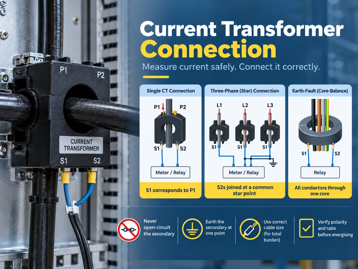
Was ein Stromwandler tut und warum die Verbindung wichtig ist
CTs sind spezialisierte Transformatoren, die nur auf eine Weise arbeiten können: Sie nehmen den Primärstrom auf und erzeugen einen proportionalen Sekundärstrom, während sie die Isolation vom Primärkreis gewährleisten. Ein 400/5 CT produziert fünf Ampere am Sekundäranschluss, wenn der Primärstrom 400 Ampere beträgt. Darüber hinaus liefert er zweieinhalb Ampere bei halber Last, und das angeschlossene Messgerät oder Relais interpretiert diese Informationen und leitet sie zurück zum Primärkreis.
| CT-Typ | Konstruktion | Typische Verwendung |
|---|---|---|
| Stab-Primär (Fenster) CT | Der Primärstrom ist ein fester Stab oder die Sammelschiene, die durch das Fenster verläuft | Schaltanlagen, Panelmessung, Nachrüstung um bestehende Stäbe |
| Gewickelter Primär-CT | Der Primärstrom ist eine Wicklung, die zu den Anschlüssen (P1/P2) geführt wird | Niedrigverhältnis- und Spezialverhältnis-Anwendungen |
| Geteilter Kern CT | Klemmen um einen bestehenden Leiter ohne Trennung | Nachgerüstete Energiemessung, Untermessung |
| Durchführungs-CT | In einen Transformator oder eine Schalterdurchführung eingebaut | Schutz von Transformatoren und Schaltanlagen |
| Kern-Balance (Null-Sequenz) CT | Alle Phasenleiter verlaufen durch einen Kern | Erdschlussüberwachung und empfindliche Leckagemessung |
Es gibt zwei wichtige Faktoren, die zeigen, wie ein CT angeschlossen werden sollte. Das Verhältnis für den sekundären Strom bedeutet, wie viel Strom der CT für einen bestimmten Primärstrom bereitstellt (zum Beispiel 400/5 oder 1.000/1). Die Last in VA gibt die Menge an Last (Messung und Relais) an, die an den CT angeschlossen werden muss, ohne seine Leistung zu beeinträchtigen. Wenn ein CT also gemäß dem richtigen Verhältnis arbeitet, aber falsch belastet ist, werden die Messwerte nicht genau sein.
Anschlüsse und Polarität: P1, P2, S1, S2
CT-Anschlüsse halten sich an eine etablierte Konvention, bei der die Verdrahtung immer eindeutig ist, sobald die Beschriftungen verstanden sind:
| Anschluss | Bedeutung | Anschlussregel |
|---|---|---|
| P1 | Primär, polaritätsmarkierte Seite | Zeigt normalerweise zur Quelle (der eingehenden Seite des Leiters) |
| P2 | Primär, nicht markierte Seite | Zeigt zur Last |
| S1 | Sekundär, entspricht P1 | Wird mit dem Instrumenteneingang S1 (oder dem “Leitungs”/Polaritätseingang) verbunden |
| S2 | Sekundär, entspricht P2 | Wird mit dem Instrumenteneingang S2 verbunden oder mit dem Stern-/Gemeinschaftspunkt in dreiphasigen Schaltungen |
Die Polaritätsregel ist eine Hauptursache für Inbetriebnahmefehler. Da S1 immer mit dem S1-Eingang des Instruments übereinstimmen muss und P1 mit der Quelle, führt eine Änderung entweder in der Ausrichtung des CT oder der Verbindung von S1 zu S2 dazu, dass die gemessenen Ströme umgekehrt werden. Richtungsabhängige Schutzanwendungen können ebenfalls fehlschlagen, ebenso wie die Messwerte der Leistung (kW), bei denen der Import als Export angezeigt werden kann. Andererseits können K & L als Markierungen von einigen Herstellern verwendet werden, das Prinzip bleibt dasselbe (K entspricht P1 und L entspricht P2), was bedeutet, dass das Typenschild die Verdrahtung diktieren muss und nicht die Lebensweise.
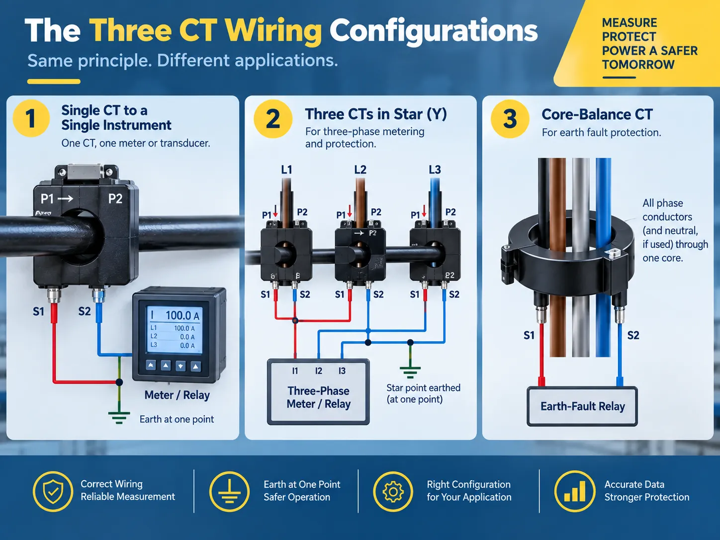
Die drei Verdrahtungskonfigurationen, die Sie tatsächlich verwenden werden
Fast jede Installation von CT wird in drei Arten von Konfigurationen unterteilt:
- Ein CT, der in Verbindung mit einem einzelnen Instrument verwendet wird. Ein CT mit einem Zähler oder Sensor: S1 wird mit S1 des Instruments verbunden, und S2 wird mit S2 des Instruments verbunden, während die sekundäre Seite an einem Punkt geerdet ist (normalerweise am Instrumentenpanel). Dies ist die Standardmethode, um es für ein dediziertes Speisepanel oder zur Überwachung des Motorstroms zu verwenden. Das gleiche Verfahren wird dreimal wiederholt, im Falle von dreiphasiger, vieradriger Messung.
- Verwendung von drei CTs in einer Y-Konfiguration für dreiphasige Messung und Schutz. Hier sind alle drei S1-Leitungen mit dem entsprechenden Instrumenteneingang für den Strom verbunden, während alle drei S2-Leitungen zu einem einzigen Sternpunkt geführt werden. Dieser Sternpunkt ist der Punkt, an dem die Sekundärseite geerdet ist. Die Sternkonfiguration wird als Standardkonfiguration für dreiphasige Energiemesser und Leistungsmesser verwendet, da sie eine genaue Kopie der Phasenströme liefert und auch einen Weg für Stromungleichgewichte bietet.
- Ein Kern-Balance-CT wird zur Erdfehlererkennung verwendet. In diesem Fall werden alle drei Phasenleiter (und der Neutralleiter, abhängig von der Anwendung) durch den einen CT-Kern geführt. Unter normalen Bedingungen entspricht die Vektorsumme der Ströme null, und somit zeigt der CT-Sekundärwert null an; jeder Erdfehler führt dazu, dass ein Teil des Stroms über die Erde anstatt über den Neutralleiter zurückfließt und ein Restsignal erzeugt, das vom Erdfehlerrelais erkannt wird. Die Verdrahtung ist in diesem Setup weniger kompliziert (nur zwei Sekundärdrähte gehen zum Relais), aber bestimmte physikalische Regeln müssen beachtet werden: Es dürfen keine anderen Drähte durch den Kern geführt werden, und der Kabelschirm oder die Rüstung darf keinen parallelen Weg schaffen, der den Reststrom ausgleicht.
Wenn derselbe CT Daten sowohl für ein Messgerät als auch für ein Schutzrelais bereitstellen muss, werden die beiden Lasten in Reihe geschaltet (zuerst das Messgerät, dann das Relais, oder durch Verwendung alternativer Kerne, wenn der CT mehrere Sekundärwicklungen hat) und nicht parallel oder mit ungenutzten Kernen. Die Schutzphilosophie hinter den Restverbindungen wird weiter in unserem Grundlagen des Erdfehler-Schutzes Leitfaden erklärt.
Das CT-Anschlussdiagramm, erklärt
Man muss ein CT-Schaltbild lesen, beginnend von der Primärseite und endend beim Messgerät. Dies ist ein Beispiel dafür, wie eine dreiphasige Messinstallation in einem Diagramm dargestellt werden würde:
| Von | Um | Leiter |
|---|---|---|
| Phase A conductor (source side) | CT-A P1 | Primary circuit — not CT wiring |
| CT-A S1 | Meter current input IA (S1) | 2.5-4 mm² copper, 600 V rated |
| CT-A S2 | Star point | Same size as S1 |
| CT-B S1 | Meter current input IB (S1) | Same size |
| CT-B S2 | Star point | Same size |
| CT-C S1 | Meter current input IC (S1) | Same size |
| CT-C S2 | Star point | Same size |
| Star point | Earth (one point only) | Grounding conductor per local code |
| Each S1/S2 pair | Shorting/test terminal block | Installed between CT and instrument |
If your project has a supplied wiring diagram, it should be used as the primary source document. However, all of the following three conventions should be used to verify it before you finalize the installation: use of S1 to S1 pairing, use of a single earth point, and presence of a shorting mechanism in the circuit. Any discrepancies in these three aspects can lead to improper commissioning and create unsafe conditions.
Step-by-step: how to wire a current transformer
- The first step is to verify the CT data and check the instrument demands. Check the nameplate for the ratio, accuracy rating, burden (VA), and polarity markings. Confirm the input rating of the instrument (1 A or 5 A) is consistent with the CT secondary because if a 5 A CT is connected to a 1 A input, the instrument will read inaccurately by a factor of five and may saturate the input.
- The device must be isolated, followed by the verification of the dead condition. The primary circuit must be de-powered, and proper lockout/tagout measures must be applied. It is important to remember that “even if the primary circuit has been isolated, there may still be a live CT secondary that is energized from another source” and hence it is important to consider every CT circuit live until proven otherwise.
- The next step is to short the secondary circuit. The shorting link on the testing terminal block needs to be closed or a proper shorting device may be used to connect S1 and S2. This procedure eliminates the danger of CT failure.
- The next step is to find the polarity that involves locating the points P1 and P2 of the primary as well as S2 and S1 for the secondary. It is essential to confirm that the primary orientation (where P1 points toward the source) and the physical arrangement matches the diagram.
- Select the proper secondary cable. Copper conductors of the appropriate size need to be used for both the burden and run length (standard 2.5 mm², 600 volts) with the goal of avoiding running power conductors in the sheath while achieving all three phases.
- Termination needs to happen at the instrument with S1 in the S1 (polarity) input on the instrument and S2 on the second input.
- Ensure that there is a grounding at only one point, typically at either the instrument or relay panel.
- Check the terminals for torque settings according to the manufacturer and apply labels to the phases including the ratio label.
- The shorting link must be removed before testing commences with the verification of the ratio and polarity.
- Turn the energizing circuit on so the circuit is reading correctly on the instrument with all three phases being noted at the current reading.

Burden and cable sizing: the calculation most installers skip
Current transformers (CTs) have a rated burden above which they will not be accurate. The burden total includes all devices connected to the secondary and the resistance of the secondary wiring:
- Instrument burden: this is the VA burden (or ohmic) specified by the manufacturer of the meter or relay. It can vary by instrument type, but is generally in the range of 0.2-1 VA per current input for modern electronic instruments and higher burdens for older electromechanical relays.
- Wiring burden: the wiring resistance is calculated as follows: 2 x one-way length x resistance per meter (for example, the resistance for 2.5 mm2 copper wiring is approximately 7.4 ohm/km), times the square of the secondary current. Depending on the run length, it is not uncommon for the instrument burden to be exceeded simply due to wiring burden.
- Connection burden: the resistance across the terminals and test blocks is generally small, but if the wiring total is close to the CT burden, this value should be included.
If the total burden exceeds the rating of the CT, it cannot provide accurate readings and may saturate during fault currents – which is when protection is needed most. Possible remedies include a shorter cable run, a larger conductor, using a lower-burden instrument, or buying a CT with a higher VA rating.
The accuracy classes themselves — 0.5 and 1 for metering, 5P and 10P for protection — are explained in our transformer accuracy classes guide.
And the ratio-selection logic for a given installation, from load current and fault level to the final nameplate choice, is covered in our current transformer ratio selection Artikel zusammengefasst.
Testing and verification
Three tests are used to ensure that a CT is installed correctly before it is allowed to carry load:
| Test | What it proves | Methode |
|---|---|---|
| Ratio test | The CT produces the expected secondary current for a known primary current | Primary injection at a fraction of rated current, or a secondary-voltage method for large CTs |
| Polarity test | S1 truly corresponds to P1 and the instrument reads forward power correctly | DC pulse or primary injection with a polarity-sensitive instrument |
| Insulation and continuity | No shorted or open secondary conductors, and adequate insulation to earth | Insulation resistance and continuity checks before energization |
Post-energization verification is equally important because you should compare the readings of the CT with a reading from a clamp meter on the primary side, verify that the readings are consistent across all three phases, and confirm that the earth-fault circuits register zero residuals on a healthy feeder.Where the CT is part of a protection scheme, that coordination — and the grounding references it depends on — is the subject of our Grundlagen der Transformator-Erdung Leitfaden erklärt.
Safety rules, and the mistakes that damage equipment
The secondaries of current transformers only flow small amounts of current at low voltages—until something goes wrong. The following are mandatory guidelines for dealing with current transformer circuits:
- Never open the current transformer circuit secondaries while the primary circuit is energized. The current transformer will attempt to generate very high voltages (hundreds or thousands of volts) across the secondary terminals when it is open, leading to an extreme overvoltage situation, core saturation, overheating, and potentially explosion and fire.
- Ground the current transformer secondary only at one point. Connecting the ground at two points will cause unnecessary current to circulate through the ground contributing to an incorrect measurement and potentially causing an unnecessary trip of protection equipment.
- Avoid installing a switch or fuse in the current transformer circuit that is not a shorting type of test block. Standard circuits may fail open which creates the same condition as an open circuit.
- Do not leave spare current transformer cores open. Short the unused coils and note them on the drawing, or future technicians may be incorrectly leading service personnel to assume that they are open circuits.
- Be sure to observe proper polarity at each connection. The S1-to-S1 and P1-to-source connections are not arbitrary conventions that may be changed later.
- Keep current transformer wires away from power and variable frequency drive (VFD) cables, and do not pass the current transformer around just a single part of the conductor in a core balance scheme.
Two other practical points to remember are that a current transformer must be hooked up with the instrument input rating matching the transformer’s secondary rating (either 1A or 5A) and that the primary conductor must pass through the window in one direction only. Passing a bar or cable back through the core backwards will reverse the effective polarity of the current transformer.For meters that must be removed for calibration, the test block should be the type that automatically shorts the CT when the instrument is unplugged; the wiring practices around metering and instrument transformers are also covered in our current transformer installation guide.
FAQ
What are the disadvantages of using a current transformer?
There are several drawbacks; having an open-circuit secondary is dangerous since it creates the possibility of serious injury; calculation of the connected load must be done correctly, or else inaccurate readings will be produced; incorrect polarity can result not only in inaccurate readings but also in malfunctioning protection devices; there is a small phase shift introduced by the CT that results in a slight inaccuracy in measurements; added expense and panel space; proper sizing is necessary, otherwise, the CT will saturate during a fault condition. Although modern electronic meters do reduce some of the problems associated with these drawbacks, all of them cannot be eliminated.
How are current transformers wired?
To connect the primary conductor through the CT there is P1 (the source side) and P2 (the load side) or the line is passed through the bar / window. The secondary side will be S1 and S2 with S1 corresponding to P1. The S1 and S2 will lead to either a meter, relay, or transducer directly for a single CT or in a star configuration for three-phase metering (three S1s to the meter and three S2s coupled to one grounded star point, etc.). There is a shorting/test terminal block mounted at the juncture of the CT and the instrument.
Does it matter which wire goes where on a transformer?
For any transformer it does; however, CTs have unique requirements. This is due to the leads having a specific polarity (i.e., S1 correlating to P1). By reversing these two leads, it causes current to flow in the opposite direction creating inaccurate power readings along with the possibility of malfunctioning protection devices. This is applicable in both transformers with respect to the primary and secondary leads.
How do you connect an electrical transformer?
In the case of an instrument transformer such as a CT: verify the ratio and the burden, isolate the transformer and prove it to be dead, short out the secondary side, identify which lead corresponds to P1 and which lead corresponds to S1; connect the correctly sized secondary cable such that S1 and S2 lead to the instrument’s respective inputs, ground the secondary at one point, label and torque the connection, remove the ground; and finally inject a known standard into the system to verify polarity and ratio. The process for connecting a power transformer differs from this procedure but still requires the individual to verify ratings, polarity, grounding, and testing before energizing load.
Referenzen
- IEEE — C57.13, Standard Requirements for Instrument Transformers
- IEC — 61869 Series, Instrument Transformers
- NFPA — National Electrical Code (Instrument Transformer Circuits)
- NETA — Acceptance Testing Specifications for Electrical Power Equipment
Fazit
The installation of the current transformer carries a lot of weight although it may seem like an unimportant task. The function of the current transformer is to reduce the amount of primary current flowing through the wire to a safe reading for the meter or relay. Therefore, you can see how important this task is in the long run. For the primary wire (P1) you will have to run wire to the source while the secondary wire (S1) will run from the current transformer to the meter or relay. If you are wiring three-phase meters, the circuits must be wired in a star pattern and grounded at a single point to earth. Use a core-balance CT for residual currents; make sure you size the secondary wire appropriately according to the burden load. Always use a test block to short out the circuit before energizing it and never break the circuit as long as current is flowing through the primary side. Make sure that you check the readings first using primary injection and then record the ratio on the sheet for future reference.