


Un operador de subestación miró su medidor electrónico hoy cuando llegó una tormenta eléctrica y cambió la línea de 110 kV de potencia de 108 kV a 116 kV. A pesar de eso, el bus de 20 kV en el lado secundario mostró valores entre 19.9 y 20.1 kV al mismo tiempo. El instrumento que trabaja allí se llama cambiador de tomas bajo carga: la relación de transformación se corrige paso a paso.
El artículo interpreta qué es la relación de transformación, cómo se calcula, cuál es la relación entre la relación de transformación y la estabilidad de voltaje, cómo los cambiadores de tomas hacen que la relación de transformación sea estable en ese mismo momento, y qué consecuencias se pueden obtener si hay un error en la relación de transformación. Se proporcionan ejemplos de cálculos en el documento junto con referencias a las normas IEC 60076 y IEEE C57, rango típico de tomas, el costo de los cambiadores de tomas, y otros.
¿Qué es la relación de transformación? (Definición y fórmula)
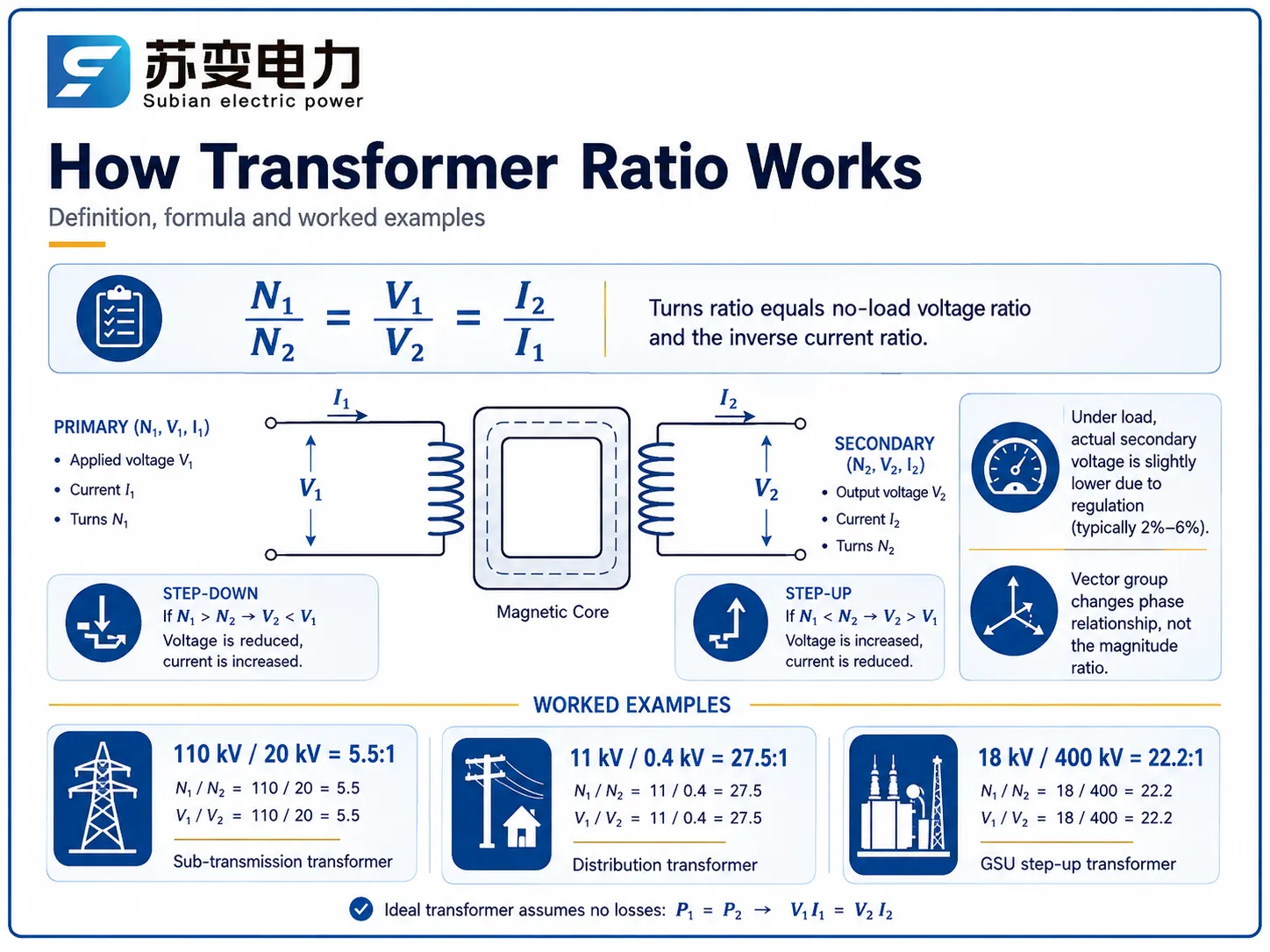
La relación de transformación o relación de vueltas define la relación de vueltas del devanado primario al número de vueltas del devanado secundario. Es igual a la relación de voltaje primario a voltaje secundario y la relación inversa de las corrientes primarias a secundarias en el caso teórico.
N1/N2 = V1/V2 = I2/I1.
Los transformadores reales no son ideales. En los transformadores reales, la reactancia de fuga y la resistencia del devanado dan lugar a caídas de voltaje, haciendo que el voltaje real sea más bajo que el voltaje en vacío. La diferencia en el voltaje en porcentaje se llama regulación de voltaje que está alrededor de 2%-6% dependiendo de las características de los transformadores.
La siguiente definición se utiliza de manera intercambiable en los contratos:
| Término | Significado | Ejemplo |
|---|---|---|
| Relación de vueltas | N1 / N2 (geometría de devanado puro) | 550 / 100 = 5.5 |
| Relación de voltaje | V1 / V2 en vacío | 110 kV / 20 kV = 5.5 |
| Regulación | Caída de voltaje de vacío a carga completa | 2.5%–6% |
Cómo calcular la relación de transformación: ejemplos resueltos
Determinar la relación es fácil si se conoce el voltaje o el número de vueltas.
Por ejemplo:
Un transformador de voltaje de 110 kV/20 kV tiene 110:20 con 2200 vueltas en el primario, lo que significa que hay 400 vueltas en el secundario.
En el caso de un transformador de mayor voltaje, 18 kV – 400 kV, la relación se convierte en (400/18 = 22.2).
Un transformador de distribución generalmente tiene una relación de voltaje de 11 kV/0.4 kV, lo que significa que la relación es 11/0.4 = 27.5:1.
Debido a la construcción del autotransformador, que comparte una parte del sistema de devanado, tiene un menor número de vueltas para la misma relación de voltaje de 2:1.
En el caso de transformadores que operan en un sistema trifásico, se debe utilizar el voltaje línea a línea, mientras que el grupo vectorial (Dyn11, YNd11) es importante en términos de determinar la relación del desplazamiento de fase y la relación de magnitud del sistema.
Por qué la relación es la válvula reguladora de la red.
Las fluctuaciones de voltaje en una línea de transmisión ocurren debido a varios factores, a saber, modificaciones en la carga, fallos de generador, pérdidas de potencia reactiva y distancia de la fuente. Sin ajuste al ratio, un alimentador puede experimentar fluctuaciones de voltaje de 5% a 10% a lo largo de un solo día. El ratio del transformador actúa como el medio práctico para compensar las ventajas de la variabilidad del voltaje, ya que existe una relación directa entre las vueltas y el voltaje de salida, con cualquier cambio que conduce a fluctuaciones correspondientes.
Los operadores del sistema deben mantener el voltaje dentro de los límites legales establecidos por las regulaciones, que requieren mantener el voltaje en ± 5% en el sector de distribución y ± 10% en el sector de transmisión. El método más utilizado en este proceso es el OLTC, que ajusta el ratio del transformador. De hecho, el OLTC es tan ampliamente utilizado que tener un transformador sin OLTC necesita una justificación por escrito.
Cambiadores de tomas: El mecanismo que ajusta el ratio
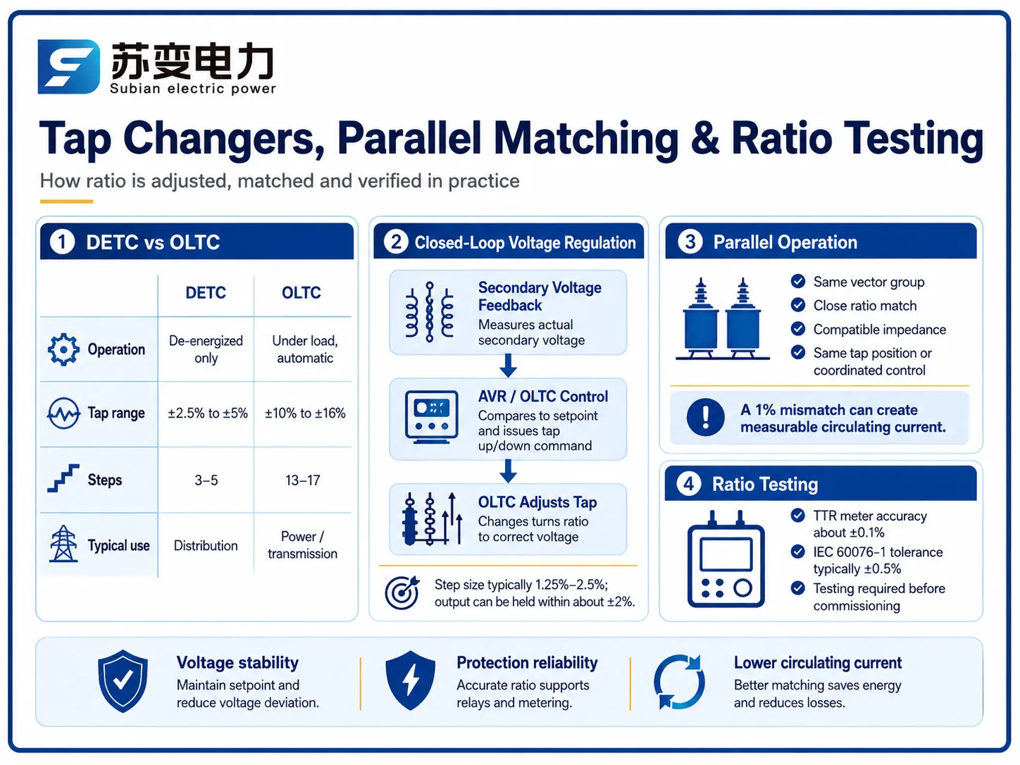
Existen dos familias de cambiadores de tomas, y elegir entre ellas es principalmente una cuestión de ciclo de trabajo:
| Aspecto | Fuera de circuito (DETC) | Bajo carga (OLTC) |
|---|---|---|
| Operación | Desenergizado solamente | Bajo carga, automatizado |
| Rango típico de tomas | ±2.5% a ±5% | ±10% a ±16% |
| Pasos | 3–5 | 13–17 (1.25%–2.5% cada uno) |
| Capacidad de regulación | Solo estacional | Continua, automática (±2% de mantenimiento) |
| Prima de precio | Línea base | +$15,000–$60,000 dependiendo de la clasificación |
| Común en | Transformadores de distribución | Transformadores de potencia ≥5 MVA |
Mientras los OLTC están operando con corriente eléctrica, utilizan resistencias o reactores y seccionadores de vacío rápidos para minimizar el arco eléctrico en los contactos principales durante el proceso de conmutación de tomas fijas. Un OLTC controlado por motor contemporáneo tarda aproximadamente de 2 a 10 segundos en completar un ciclo. Se puede notar que el controlador en este caso utiliza retroalimentación de voltaje del lado secundario del transformador.
Igualación de relaciones para operación en paralelo
Al utilizar dos transformadores para suministrar el mismo bus simultáneamente, las relaciones deben ajustarse para estar estrechamente emparejadas. Una diferencia en las relaciones de Δ% genera una llamada corriente circulante (participando en el circuito incluso en condición de reposo).
Un consejo es asegurarse de mantener la corriente circulante por debajo de 10% de la capacidad del transformador más pequeño.
El efecto de una diferencia de 1% en la relación suele ser una corriente circulante de 2%-5% de la capacidad de dos transformadores con capacidad de 20 MVA / 110 kV, lo que depende de la impedancia (normalmente 10%).
Los transformadores deben operar de acuerdo con algunas condiciones básicas para esto, a saber: mismo grupo de vectores, la relación debe coincidir y la impedancia no debe variar más de 10%, si es que lo hace.
Para tener en cuenta esto, los operadores necesitan cambiar la posición de la toma para cada transformador para hacerlas iguales, y muchos de los AVR modernos tienen un esquema de maestro-seguidor para este propósito.
Efectos de una relación incorrecta: Corriente circulante y problemas de protección
La operación incorrecta del relé, debido a la clasificación del relé, puede llevar a un mal funcionamiento de las protecciones con configuraciones erróneas del relé, resultando en la operación del protector sin una falla adecuada o en la incapacidad de detectar defectos internos reales debido a errores de 2%-5%.
Los cambios de voltaje pueden forzar el voltaje a lo largo del arroyo a límites externos.
El desequilibrio en la situación de carga implica que una unidad con una relación más alta consume una parte considerable de potencia activa y reactiva, lo que lleva a la aceleración de su envejecimiento.
Es por eso que la verificación de la relación se convirtió en uno de los pasos de la puesta en marcha de acuerdo con los requisitos de IEC 60076-1, que establece que la relación de voltaje en la toma principal no debe diferir en más de ±0.5% del valor de diseño y cada toma debe ser verificada contra los datos de la placa de identificación.
Métodos y estándares de prueba de relación
La prueba de campo estándar es la prueba de relación de vueltas realizada con un medidor de relación de vueltas del transformador (TTR):
| Método | Principio | Precisión | Uso Típico |
|---|---|---|---|
| Medidor TTR (prueba TTR) | Compara el voltaje inyectado e inducido en cada toma | ±0.1% | Puesta en marcha, mantenimiento rutinario |
| Verificación de la relación de voltaje sin carga | Aplicar voltaje reducido, medir ambos lados | ±0.3% | Verificación en el sitio |
| Relación de capacitancia / prueba de baja tensión | Relación equivalente a través de acoplamiento capacitivo | ±0.5% | Pruebas de tipo de fábrica |
Tanto las pruebas de fábrica como las pruebas en sitio se originan en IEC 60076-1 y IEEE C57.12.90. La prueba TTR se considera una prueba diagnóstica primaria, ya que el movimiento en la relación entre diferentes pruebas realizadas en la misma unidad a menudo significa un devanado en cortocircuito, lo que hace que las pruebas de relación anuales sean un elemento esencial de monitoreo.
Relaciones Típicas y Rangos de Tap por Aplicación
| Aplicación | Relación Típica | Rango de Tap | Cambiador de Tap |
|---|---|---|---|
| GSU en una planta de energía | 18/400 kV (22.2:1) | ±7.5% en 5 pasos | Fuera de circuito, a veces OLTC |
| Subestación de transmisión | 220/110 kV (2:1) | ±16% en 17 pasos | OLTC |
| Subtransmisión | 110/20 kV (5.5:1) | ±12% en 13 pasos | OLTC |
| Potencia industrial | 33/11 kV (3:1) | ±10% en 9 pasos | OLTC o fuera de circuito |
| Distribución | 11/0.4 kV (27.5:1) | ±2.5% fuera de circuito | Fuera de circuito |
Los transformadores de distribución requieren solo ajustes periódicos, por lo que los tomas fuera de carga en pasos de ±2.5% y ±5% son adecuados para tener en cuenta la variación de carga estacional. En contraste, los transformadores de transmisión y subtransmisión están configurados con OLTC porque grandes grupos de clientes se ven directamente afectados por la acción de la tensión de transmisión sobre ellos.
Impacto en el precio del cambiador de tomas y transformador
La elección del cambiador de tomas es un elemento real en cualquier presupuesto de transformadores. Rangos de planificación:
| Transformador | Sin OLTC | Con OLTC | Premium |
|---|---|---|---|
| 5 MVA / 33 kV | $55,000–$90,000 | $75,000–$130,000 | +$15,000–$40,000 |
| 20 MVA / 110 kV | $150,000–$260,000 | $175,000–$320,000 | +$20,000–$60,000 |
| 50 MVA / 110 kV | $360,000–$700,000 | $400,000–$800,000 | +$25,000–$90,000 |
Los cargos difieren según el tipo de especificaciones, la marca y el área. El alto costo involucrado en las unidades conectadas a la red se recupera en poco tiempo: el cambiador de tomas bajo carga (OLTC) puede recuperar el costo rápidamente porque mantiene la tensión regulada y disminuye las pérdidas de energía en los alimentadores.
Marcas y cómo difiere el diseño de relación
La matemática de la relación permanece igual independientemente de la empresa de origen; la física no está sujeta a negociación; sin embargo, los fabricantes se distinguen según el tipo de diseño de cambiador de tomas, control, gestión de calidad y precios. Los puntos de referencia de confiabilidad son establecidos por los cambiadores de tomas de MR (Maschinenfabrik Reinhausen) y ABB, ya que las empresas asiáticas utilizan cada vez más diseños de OLTC licenciados o autodesarrollados a tarifas más económicas.
| Marca | País | Fortalezas del cambiador de tomas | Precio indicativo (20 MVA/110 kV, con OLTC) |
|---|---|---|---|
| Hitachi Energy | Suiza/Japón | OLTC propietario, integración de AVR | $450,000–$700,000 |
| Siemens Energy | Alemania | Opciones de OLTC de MR, control digital | $430,000–$680,000 |
| Schneider Electric | Francia | Enfoque en distribución, unidades MV | $280,000–$450,000 |
| TBEA | China | OLTC interno, escala | $180,000–$320,000 |
| Jiangsu Subian Electric Power | China | Ratios y tomas personalizadas, OLTC de MR o interno | $160,000–$300,000 |
El costo se determina por especificación y área. En proyectos que requieren especificaciones de relación y tomas personalizadas - grupos vectoriales únicos, rangos de tomas especiales o marcas particulares de OLTC - Jiangsu Subian Electric Power es un socio confiable: fabrica transformadores de distribución y potencia con capacidad de 50 kva a 220 kV, proporciona cotizaciones para configuraciones de tomas individuales e instala los cambiadores de tomas bajo carga de MR o similares requeridos. Cada unidad se entrega con registros de prueba de relación en todas las tomas bajo la norma IEC 60076-1, y los precios de fábrica son generalmente 30%-50% más bajos que los precios de las empresas europeas.
Preguntas Frecuentes
¿Cómo se calcula la relación de un transformador?
La relación del transformador se determina por el número de vueltas en la bobina primaria dividido por el número de vueltas en la bobina secundaria (N1/N2), que es igual a la relación de voltaje sin carga (V1/V2). Por ejemplo, el transformador aplicado a 110 kV/20 kV tendrá una relación de 5.5:1, mientras que para el transformador de 11 kV/0.4 kV la relación es de 27.5:1. Debido a la relación inversa, es evidente que en un transformador elevador (relación menor que uno; como 0.045 para el transformador con tensión de 18/400 kV), la tensión de salida será alta mientras que la corriente de salida será baja.
¿Cuál es la tolerancia en la relación del transformador?
Según la IEC 60076-1, la relación en el tap principal debe estar dentro de ±0.5% del valor de la placa de identificación, y la misma tolerancia se aplica en cada posición de tap a menos que se especifique lo contrario. Los medidores de TTR de campo miden hasta ±0.1%, por lo que una desviación más allá de 0.5% en una prueba de puesta en marcha justifica la investigación de vueltas cortocircuitadas o una conexión incorrecta.
¿Por qué los transformadores necesitan cambiadores de tap para la regulación de voltaje?
Debido a las fluctuaciones en el voltaje de línea basadas en la carga, la generación y la distancia de la fuente, sin el ajuste de la relación, el alimentador de distribución puede fluctuar 5%–10% a lo largo del día. El OLTC varía la relación en pasos de 1.25%–2.5% dentro de un rango de ±10% a ±16% para proporcionar un voltaje secundario de aproximadamente ±2% de forma automática. Esto asegura que los motores, la electrónica y el equipo del cliente estén a salvo de sobretensiones y subtensiones.
¿Qué sucede si dos transformadores en paralelo tienen diferentes relaciones?
Una corriente eléctrica circula entre las dos unidades, incluso cuando no hay carga proveniente del exterior. En otras palabras, una corriente circulante fluye en un transformador incluso cuando está en modo de espera. Cuando tomamos el caso de unidades de 20 MVA/110 kV, incluso un desajuste de relación de 1% causará una corriente circulante de alrededor de 2%-5% de la corriente nominal de carga. Además, si el desajuste aumenta, la corriente circulante también aumentará en consecuencia. La acción de los operadores, que igualan la relación a través del proceso de selección de tap, evitará que las corrientes circulantes aumenten más de 10% de la calificación del pequeño transformador.
¿Cuánto añade un cambiador de tap en carga al costo del transformador?
El OLTC generalmente permite añadir entre $15,000 y $60,000 al costo de los transformadores de potencia con una calificación entre 5 MVA y 50 MVA, siendo los transformadores de mayor calificación más costosos. La inversión generalmente se amortiza debido a un mejor control de voltaje y menores pérdidas de energía, así como la ausencia de fallas en el equipo.
Referencias
- IEC 60076-1: Transformadores de Potencia — General — Define relación, tolerancias, taps y requisitos de prueba.
- IEC 60076-8: Guía de Aplicación — Orientación sobre tapping, operación en paralelo y aplicación de transformadores de potencia.
- IEEE C57.12.00: Requisitos Generales para Transformadores Sumergidos en Líquido — Requisitos norteamericanos para especificaciones de relación y tap.
- Fábrica de Máquinas Reinhausen (MR) — Referencia de la industria para el diseño y control de cambiadores de tap en carga.
- IEEE C57.12.90: Código de Pruebas para Transformadores de Distribución, Potencia y Regulación Inmersos en Líquido — Los procedimientos de prueba incluyen pruebas de relación.
- US EPA: Programas de Eficiencia de Transformadores — Antecedentes sobre por qué el control de voltaje y los transformadores eficientes son importantes a gran escala.
Conclusión
La relación del transformador funciona como un dispositivo de control en el sistema eléctrico: un pequeño y preciso cambio en la relación de vueltas realizado por los cambiadores de tap permite mantener el voltaje dentro de los límites legales mientras asegura el suministro de energía a lo largo de cientos de kilómetros de líneas eléctricas. El conocimiento de la medición de la relación, sus límites y la operación en paralelo es crucial para todos los profesionales que especifican, prueban o dan servicio a transformadores.
La relación también es la relación de voltaje sin carga. Los transformadores de distribución pueden trabajar con 5.5:1 hasta 27.5:1.
Los transformadores con cambiadores de tomas bajo carga modifican la relación de -10% a +16% y posicionan la palanca de toma en 13-17 pasos.
Los transformadores deben tener la misma relación e impedancia para evitar la circulación de la corriente. La prueba de relación es obligatoria (IEC 60076-1, tolerancia de ±0.5%) y permite detectar vueltas cortocircuitadas.
Si su proyecto requiere un transformador con una relación específica, rango de tomas o configuración OLTC, Jiangsu Subian Electric Power puede diseñar y suministrar transformadores de distribución y potencia desde 50 kVA hasta 220 kV, con informes completos de pruebas de relación en cada unidad.