


Les transformateurs subissent une série de tests à différents moments de leur cycle de vie, chacun de ces tests appartenant à une catégorie différente, et la réussite est mesurée avec des critères différents par test. Par exemple, tester un simple transformateur de contrôle de 12 V à l'aide d'un multimètre n'est pas du tout similaire à la mise en service d'un transformateur de distribution de 1 MVA, à part le fait que le résultat est le même dans les deux cas. Cet article explique ce que chaque test permet d'atteindre, ce qui est nécessaire pour les réaliser, comment interpréter les résultats, et les règles qui doivent être observées par tous ceux ayant une certaine conscience de la sécurité.
Réponse en bref : Le multimètre est capable d'effectuer des vérifications de continuité, de résistance des enroulements et de rapport de tension pour les petits transformateurs, ce qui couvre la plupart des fonctions. Pour les plus grands, cependant, il est nécessaire d'utiliser une batterie standard ; celle-ci doit vérifier le rapport de transformation dans une plage de ±0,5% par rapport à la plaque signalétique pour chaque prise, la résistance des enroulements pour phase à phase et avec les valeurs d'usine, la résistance d'isolation avec un indice de polarisation supérieur à 2,0. Les transformateurs remplis d'huile doivent être testés pour leur résistance à l'isolation et l'analyse des gaz dissous conformément aux normes d'usine spécifiées dans la norme IEC 60076 et IEEE C57.12.90.
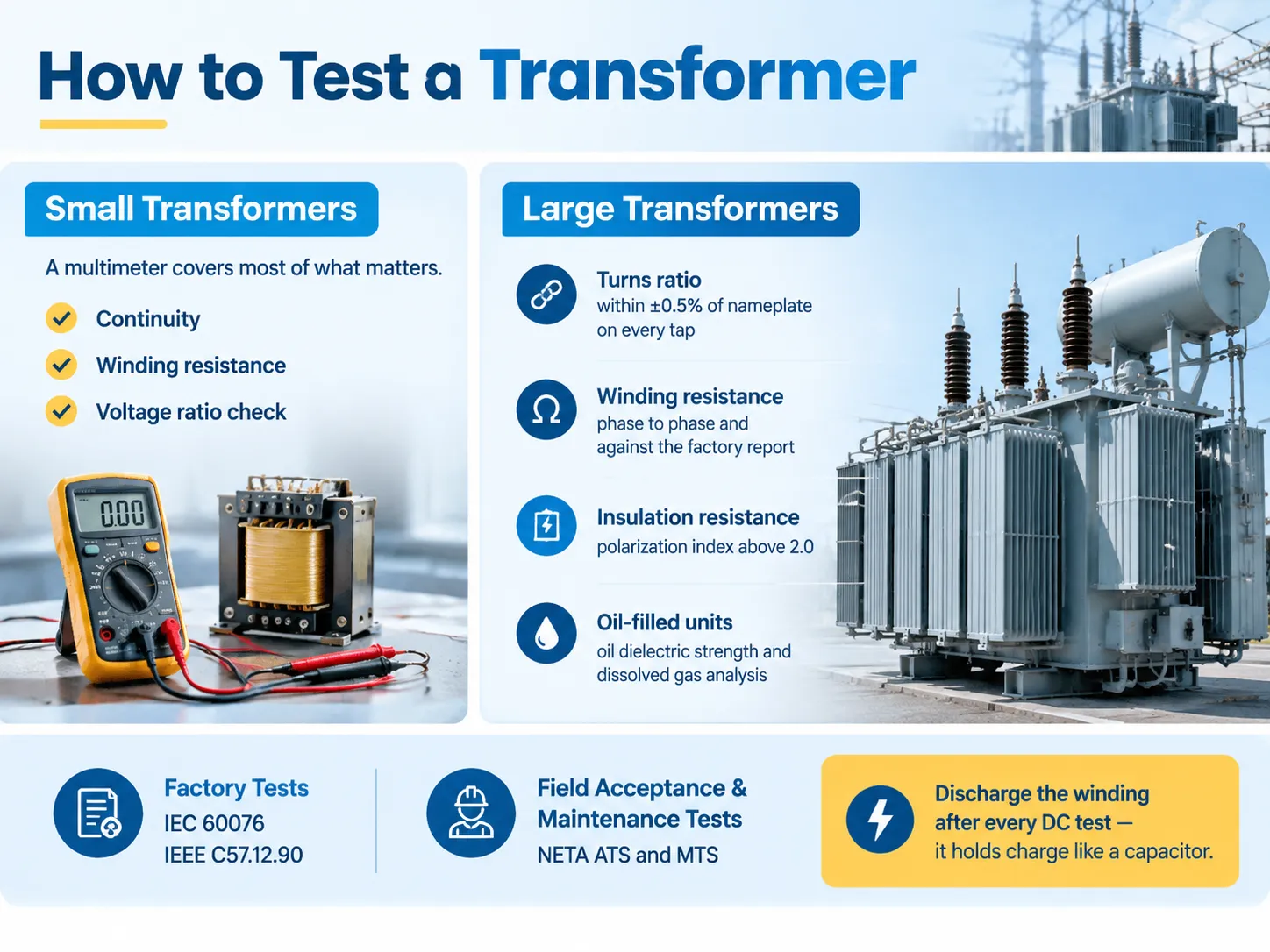
Les quatre types de tests de transformateurs
Trier les tests par moment où ils sont réalisés est le moyen le plus rapide de comprendre pourquoi il y en a tant.
| Catégorie | Objectif | est négligeable | Références réglementaires |
|---|---|---|---|
| Tests de routine (en usine) | Contrôle de qualité sur chaque unité construite | Pendant la fabrication, chaque unité | IEC 60076-1, IEEE C57.12.00 |
| Tests de type (conception) | Prouver qu'une conception répond à ses spécifications | Une fois par conception, ou sur un prototype | IEC 60076-3, IEEE C57.12.90 |
| Tests spéciaux | Preuves supplémentaires spécifiées par le client | Sur demande | Dépendant du contrat |
| Tests d'acceptation / de mise en service | Confirmer que l'unité est arrivée intacte et est correctement installée | Avant la première mise sous tension | NETA ATS, IEEE C57 |
| Tests de maintenance | Suivre l'état au cours de la durée de service | Périodiques, ou après un défaut ou un événement | NETA MTS, IEEE 62 |
La différence entre les tests d'acceptation et les tests de maintenance est plus significative qu'il n'y paraît. Les spécifications de tests d'acceptation NETA (ATS) s'appliquent à l'équipement avant son utilisation et établissent la base pour le même appareil. Les spécifications de tests de maintenance (MTS) s'appliquent au même équipement après qu'il commence à être utilisé, ce qui est similaire mais pas le même processus. Les tests eux-mêmes sont similaires, même si les résultats et les objectifs sont différents.
Pour la mise en service, il y a une autre distinction importante à connaître lors de la planification du calendrier : il y a la liste de contrôle de mise en service avec différentes étapes où l'achèvement d'une étape est crucial pour la suivante. Travailler à travers les étapes dans le bon ordre, et enregistrer les valeurs de référence au fur et à mesure, est la pratique décrite dans cette liste de contrôle de mise en service des transformateurs.
Outils et ce que chacun vous dit
| Instrument | Test | Ce qu'il détecte |
|---|---|---|
| Multimètre numérique | Vérifications de continuité, de rapport de tension, d'alimentation | Enroulements ouverts, erreurs de rapport brut, alimentation manquante |
| Ohmmètre à faible résistance / micro-ohmmètre | Résistance des enroulements | Connexions lâches, brins cassés, mauvais contacts de prise |
| Rapport de transformation (TTR) défini | Rapport de transformation et polarité | Mauvais enroulement, enroulements court-circuités, enroulement ouvert, mauvaise connexion |
| Testeur de résistance d'isolation (Megger) | IR, PI, DAR | Humidité, dégradation de l'isolation, contamination |
| Facteur de puissance d'isolation / ensemble tan delta | Facteur de dissipation, capacité | Vieillissement de l'isolation ; état des bushing dans les configurations GST/UST |
| Kit de test d'huile (cellule BDV, humidité) | Résistance diélectrique de l'huile, teneur en eau | Contamination de l'huile et infiltration d'humidité (uniquement pour les remplissages liquides) |
| Appareil d'échantillonnage DGA | Analyse des gaz dissous | Arc, défauts thermiques, décharge partielle, vieillissement de la cellulose |
| Analyseur SFRA | Analyse de la réponse en fréquence de balayage | Déformation de l'enroulement après transport ou défaut de passage |
| Clamp meter and thermal camera | Load current and thermal survey | Unbalanced loading, hot connections, cooling problems |
It is worth warning about two matters. The use of a megger on a transformer while it is still connected to electronic protection, a lightning surge protector, or a control panel will ruin them. Always make sure to isolate and disconnect them first! Another matter is a thermal inspection — this means nothing if the transformer is de-energized.
Before You Test: Visual, Mechanical and Safety
It is noted that half of the faults are discovered as a result of an appropriately performed visual inspection.
- Plate and documents. Check the voltage, the rated capacity, vector group, impedance, temperature classification, and the tap settings against the test program. Testing a unit against an incorrect nameplate may ruin your day.
- Physical condition. Shipping damage, oil leakage, damage to bushings, loose connections, moisture in the terminal box, displacement of the core brackets, malfunctioning pressure gauges.
- Oil level and condition for the oil-filled equipment. Cloudy or discolored oil is a discovery by itself.
- Grounding and bonding. Earth grounding for the tank, neutrality grounding, grounding of the core, and the continuity of the relevant bonding jumpers.
- Isolation and lockout. Isolate power supply, apply locks and tags, make sure it is dead at the working point. arc-flash PPE standards according to the voltage class you work with will be governed by NFPA 70E.
Multimeter Tests You Can Run Without Power
A multimeter won’t give you a complete picture but will provide answers to two critical questions for a small transformer: whether a winding is open and if the ratio is about correct.
Continuity and resistance. Be sure to isolate the transformer and check each winding by itself. An open reading indicates there is a break in the winding or its connection. A near-zero reading on a winding that should have some resistance suggests there is a shorted turn or an open lead. In a step-down transformer, the primary should have much higher DC resistance than the secondary since it uses thinner wire and has more turns.
Voltage ratio with power on. Put your rated AC voltage on the primary and measure the secondary on your meter set to AC volts. The primary voltage divided by the voltage you measure on the secondary should give you the nameplate ratio. Though you won’t have a load, the reading will be slightly off because of drops across the winding, but it should be close. Often, an incorrect reading is indicative of being on the wrong tap, incorrectly wired, or that the transformer is not as labeled. For example, a 12 V transformer should give you 12 V out at the secondary while supplying 120 V input. If you read 6 V or 24 V you are either on the wrong winding or incorrect tap.
What a multimeter cannot do: it cannot locate a single short turn accurately, cannot determine insulation state (checking the insulation resistance between windings requires a DC source and not the low_voltage ohms range of the multimeter), and cannot determine the ratio as accurately as a TTR device can. For anything more than a small furnace or control transformer, a multimeter should merely be the first step.
Two situations have proved troublesome: whether the secondary of a furnace or HVAC control transformer provides 24 V AC while the thermostat is calling. A secondary that fails under load indicates problems in the circuit downstream instead of transformer failure. The second troublesome case involves high-voltage transformers in microwave ovens. In this case, the best course is not to test live at all.
Turns Ratio (TTR)
The turns ratio test is one of the biggest informative single tests you can perform. It is also the one most often missed in the field.
The TTR applies a low voltage to one of the windings and monitors the voltage induced on the second winding, taking the ratio measured and comparing it against the nameplate. The acceptance criterion for the test is given in IEEE C57, which says that this should be no more than ±0.5% from the calculated value in all windings.
The test earns its money by interpretation.
- If the tap-step percentage is the same in all taps, the machine has been placed on the wrong tap; this is not a defect but a commissioning error
- If there is one tap off — there are problems with the tap lead or tap changer contact.
- One of the phases is missing measurements and has high exciting current — so there are some shorted turns.
- If there is no reading at all — it is an open winding or a broken lead.
A TTR that is out of tolerances does not allow energization until it has been explained.
Winding Resistance
Winding resistance is measured using a low-resistance ohmmeter with DC current, which is injected through each winding and is measured for every phase and tap. The reading is given in milliohms. Comparisons are made from phase against phase, factory reading per temperature, and tap to tap.
As copper resistance varies with temperature, all readings must be adjusted to a standard temperature for comparison. One degree change is insignificant; however, a ten-degree change can present reading as faulty. The only useful number is not absolute but relative, that is, one phase facing high against the others means a connection fault in that phase, while a reading deviating from its factory mark indicates a developing connection fault.
Insulation Resistance, PI and DAR
The following test allows to evaluate moisture and insulation degradation and, at the same time, the test that is most likely to be done incorrectly.
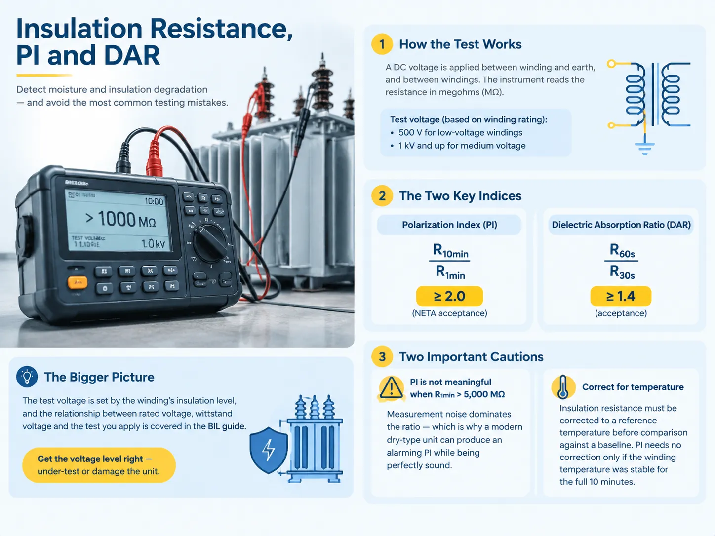
Insulation resistance test is based on using DC at the voltage acceptable for any winding in order to determine insulation resistance, usually, the value of 500 V is used for the low voltage winding and the one of 1 kV and higher is applied to medium voltage windings. Modern solid-state devices allow doing this task easily, but the real difficulty lies in the interpretation of the obtained result.
However, the actual importance goes to other two parameters. The polarization index (PI) is determined as the resistance value at 10 minutes’ time interval divided by the one at 1 minute which value should be equal to a minimum of the accepted 2.0. The dielectric absorption ratio (DAR) is another parameter which is determined as the resistance value at 60 seconds divided by the one at 30 seconds and which should have the minimum value of 1.4.
However, presence of the PI and DAR will have little importance if some practical considerations are ignored. The first important point to take into account is that the PI measurement becomes unacceptable when the one-minute resistance value exceeds 5,000 MΩ value, because no measurement error dominates the result.
The test voltage itself is set by the winding’s insulation level, and the relationship between rated voltage, withstand voltage and the test you apply is the subject of its own explanation of basic insulation level (BIL). Get the level wrong and you either under-test the unit or damage it.
Dielectric Withstand, Partial Discharge and Impulse
The above-mentioned tests demonstrate that the insulation can endure whatever challenges the network may pose. These tests are factory-standard tests and can all be repeated in the field using various equipment if one wants to perform tests on bigger transformers.
- Power frequency withstand test. The test subject is subjected to a specific test voltage for a specific time while voltage is gradually raised from one-quarter of the test value up to the value. The pass criterion is that no breakdown or flashover occurs during the test. The standards that are used during the tests are prescribed in IEC 60076-3.
- Lightning impulse test. The tests imitate 1.2/50 µs impulses to imitate lightning strikes at the levels for the particular voltage class.
- Partial discharge measurements. The tests make PD measurements for local insulation failures normally undetectable by withstand testing. Usually, the acceptable value for new transformers is about 10 pC at the nominal phase-to-eart voltage.
All of them are destructive tests. Avoid improvising while performing them on a site and do not test a service-aged unit with a voltage bigger than the specified in the nameplate.
No-Load, Load Loss and Impedance
Three tests evaluate the electrical characteristics of the transformer in terms of its design.
Due to the supervision of the excitation (no load) test, the application of the rated voltage on one winding occurs while the other winding is switch off, allowing voltage, current, and power measurements. A too high inducted current suggests that there has occurred a malfunction on the internal circuitry due to the shorting of some turns or fails on the core. For a transformer using three-legged core type ailings of outer settling should be bigger than the readings of the core itself; otherwise it indicates some problems and supposed malfunction.
When evaluating load loss and impedance, the winding of the transformer is shorted, while a power supply provides the rated voltage and thus reaches the rated current. The value of the impedance so calculated is compared with that shown on the nameplate and is allowed a deviation of about ±7.5% not to fall out of the two-winding factory, It is necessary to stress the importance of the impedance coefficient in practical use of the transformer, as it is the main and crucial factor influencing the efficiency of the whole device in the future.
Oil Tests and Dissolved Gas Analysis
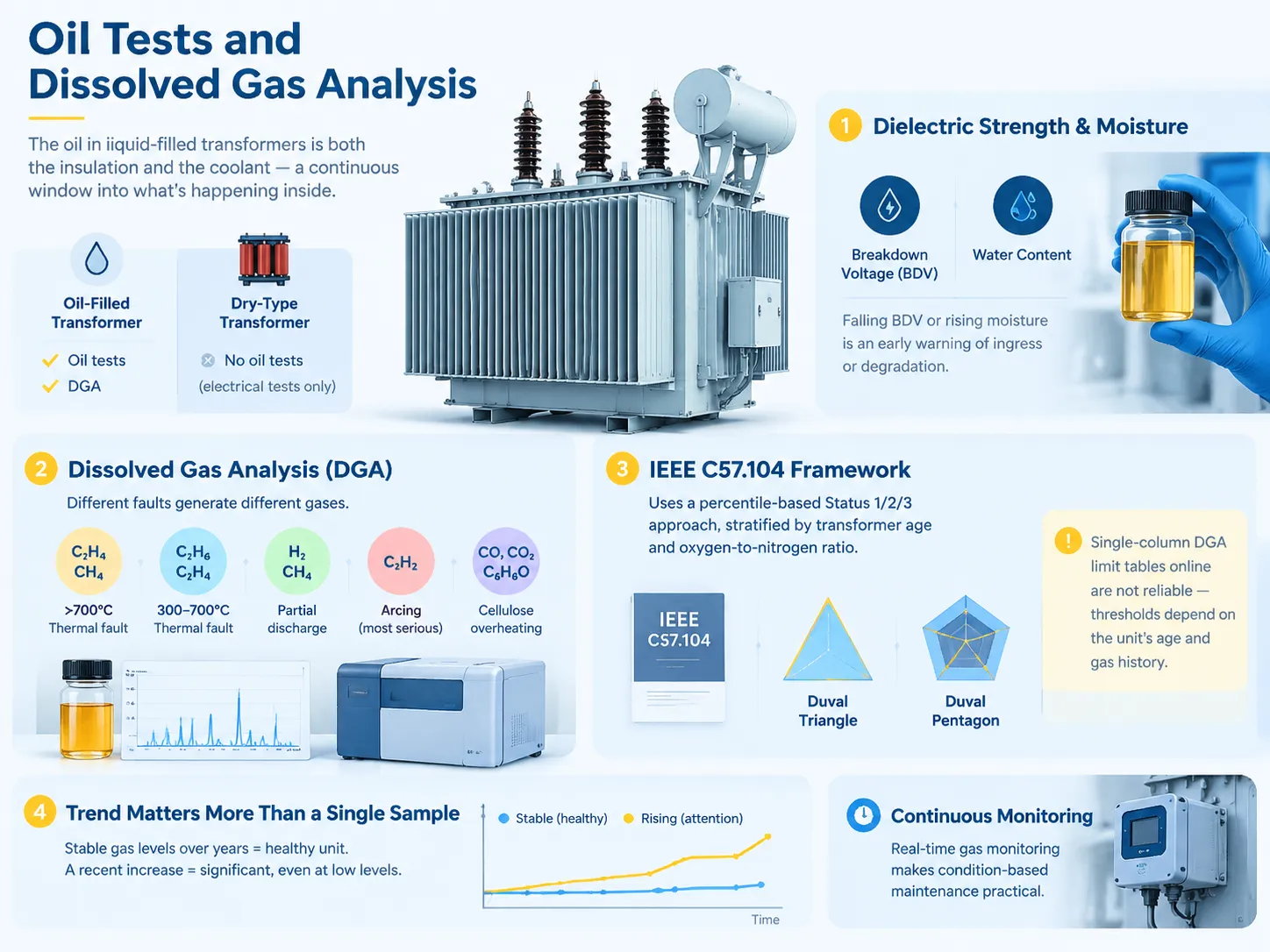
For oil-filled transformers, oil acts both as an insulator and as a coolant, thus it is a constant indicator of what is happening in the transformer tank. As for dry-type transformers, there is no oil and thus there is no oil testing. Hence, testing relies on electrical means only.
Dielectric strength and moisture test. Oil test involves breakdown voltage and moisture content tests. If there is a decrease in the BDV of oil or an increase in the moisture, it indicates the ingress of water in the transformer or deterioration of oil. Fortunately, both of those parameters are cheap to measure.
Dissolved gas analysis. DGA is by far the most advanced measure for oil immersed transformers and it works because various faults produce different gases. For example, thermal faults above 700 degrees Celsius generate ethylene and methane; for thermal faults between 300 and 700 degrees Celsius, ethane and ethylene are produced; partial discharge is characterized by the presence of hydrogen and methane while arcing results in generating of acetylene which is known to be a serious indication of the fault; as for overheating of cellulose, it is characterized by carbon monoxide, carbon dioxide and furfural.
Interpretation is outlined by IEEE C57.104 which is currently based on percentiles rather than total combustible gas content. Other methods that can be used include Duval triangle and pentagon. That is the reason why there is no point in using any tables available online in terms of DGA limits, as the limits are determined by the specific equipment’s age and gas history.
Trend is much more important than a single sample. If gas readings are stable for many years, this is a good sign even if the values are high. On the contrary, increase in readings is alarming even if the readings are not high. This is the reason why the testing should be done on a regular basis and compared to previous data during each testing.The monitoring practice that makes this practical, including continuous gas monitoring instead of periodic sampling, is described in this overview of real-time transformer gas monitoring for condition-based maintenance.
Polarity, Vector Group and Phasing
This testing will show that the transformer has been hooked up in accordance with the information given on the nameplate, ensuring safety of parallel operation. The single-phase polarity test is used to determine whether the winding is of additive or subtractive polarity. The three-phase phase relation test confirms the vector group and phase sequence of the transformer. Mismatching polarity or vector groups of two transformers being operated in parallel results in the generation of a current that is strong enough to burn both transformers. Hence, this is a critical stage of commissioning.
Reading the Numbers: Pass, Investigate or Stop
| Test | Typical acceptance | Investigate | Stop and diagnose |
|---|---|---|---|
| Turns ratio (TTR) | Within ±0.5% of nameplate, all taps | Any consistent deviation | Single phase off, or no reading |
| Résistance des enroulements | Balanced phase to phase, matches factory report | A few percent spread | One phase clearly high or drifting |
| Résistance d'isolation | Above the baseline for the class | Falling trend against previous tests | Below the minimum for the voltage class |
| Indice de polarisation | ≥ 2,0 | 1.5–2.0 | Near 1.0 (unless 1-minute IR exceeds 5,000 MΩ) |
| Impédance (%Z) | Within ±7.5% of nameplate | Modest deviation | Large deviation — likely winding deformation |
| DGA | Status 1, stable trend | Rising trend or Status 2 | Acetylene present, or Status 3 |
| Oil BDV | Above the specified minimum | Falling against baseline | Low enough to compromise insulation |
What should be done when the tested unit failed is to explain why it failed instead of making a judgement about it. If a unit shows excessive ratio because a wrong tap was used, it can be fixed in five minutes. If a dry-type unit shows somewhat low PI while possessing very high IR value, it indicates the presence of measurement noise, not degradation.Diagnostic discipline at this stage is what stops a serviceable transformer being scrapped on the strength of one number, and the systematic route through the common failure modes is set out in this guide to troubleshooting power transformer faults.
How the Test Battery Changes by Transformer Type
The basic electrical tests are universal. The only thing that changes is the details and the stress given.
- Distribution transformer (with oil). The entire battery of electrical tests plus oil BDV, moisture and DGA. The standard tool for roadside and pit-type transformers
- Dry transformers. The same battery of electrical tests but without the oil tests. For dry-type machines, the procedures are automatic and described here in the dry-type transformer routine tests description. PD measures are quite significant because there is no oil to test.
- Large power transformers. In addition to all the electrical tests mentioned above, the insulation power factor test (in GST, GSTg, UST versions), capacitance test, bushing power factor test against nameplate C1 parameter; SFRA method for everybody will be added.
- Instrument transformer. Ratio and polarity checks, and also accuracy class testing are to be performed according to their own standards, not according to that of the large power transformers.
- Small and single-phase transformers. Simple tests are usually enough: continuity test, resistance test, ratio test, voltage test.
Safety Rules That Are Not Optional
Discharge after every DC test. TTR, insulation resistance and power factor tests all charge the winding and a winding retains this charge, like a capacitor, after disconnection. It must be grounded using a grounding stick immediately after testing and kept grounded until next step. This is how technicians can get shocked by a deactivated meter.
Prior to carrying out any resistance or continuity measurement isolate and lockout. The meter can be destroyed, and operator can be hurt if an ohmmeter is used on a powered circuit.
Unplug surge protectors, protective relays, and control circuits before testing insulation resistance. High voltage will damage them.
PPE must correspond to the voltage class according to NFPA 70E standards and the results of the arc flash study conducted at the facility, not to the tradition.
FAQ
How to test if a transformer is working?
To check a smaller transformer, first isolate it, conduct winding continuity checks and DC resistance measurements on it using a multimeter, and then apply the rated AC voltage to its primary side and verify that the secondary side reads almost the rated voltage on it. For larger transformers, the passed field check consists of a turns ratio test on every tap that is within ±0.5% of nameplate specification, insulation resistance measurement yielding a polarization index higher than 2.0, and visual and thermal inspections under load. In case of oil-filled transformers, the boil dielectric strength test and dissolved gas content test are also required. The term “working” means that all said above have passed rather than the secondary having some kind of voltage on it.
What are the methods of testing a transformer?
There are prominent electrical methods including turns ratio (TTR), winding resistance, insulation resistance using polarisation index and dielectric absorption ratio, insulation power factor or tan delta, applied voltage (power frequency withstand), lightning impulse, partial discharge, excitation or no-load loss, load loss with short-circuit impedance, polarity and phase relationship etc. In terms of mechanical or chemical methods, SFRA and oil dielectric strength moisture testing and dissolved gas analysis can be used for transformers. The choice of method depends on the type of transformer, size and stage of its life.
How to test a 12V transformer with a multimeter?
Make sure that the transformer is disconnected from loads. Set the meter to ohms and measure the resistance across the primary: it must show positive resistance, not an open circuit and its value should be greater than that of the secondary winding since the latter usually consists of thicker wire and has fewer turns. If the transformer can be used with mains supply on the primary, supply the transformer with the rated voltage and measure the secondary voltage with the meter set to the AC volts — the meter must read close to 12 Volts without load and may show a little higher voltage. If the readings are half or double the expected value, the readings have been taken from some other winding. Do not connect mains to the transformer if its primary circuit rating is unknown.
How to test a transformer with a multimeter without power?
Checking continuity and DC resistance without power only is possible. Using the two meters you need to check winding by winding. If your reading is infinite ohms, you have an open circuit problem in the winding or lead. If the reading is almost zero while in winding having considerable resistance, you have a short circuit. By comparing primary and secondary resistance, you can figure out whether the unit is step-down transformer and how it is wired in general. However, you cannot establish turns ratio, insulation resistance between the windings or locate a single shorted turn.
How to test a transformer with a megger?
The next step is to isolate the transformer as completely as possible. Disconnect the surge arresters, protection relay and control electronics first. Decide on the test voltage for winding insulation class — low voltage windings have 500 V DC, and medium voltage has 1 kV or higher. Winding to earth is measured first, and then winding to winding. Ensure the test is conducted for the full duration — don’t just read the needle right away. Polarization index is obtained from the reading done after 1 min and 10 min; NETA acceptance is above 2.0, dielectric absorption ratio is above 1.4. Also remember to adjust your raw insulation resistance for temperature before comparing it with the baseline values.
Can I test a transformer without disconnecting it?
Although it is possible to apply ratio and continuity tests to a circuit that has been disconnected, in the case of insulation testing, the insulation resistance test applies a high voltage direct current which results in damaging any equipment that may be connected. Thus the disconnection of the circuit is not simply a procedure but a necessary prerequisite for making such tests valid.
Références
- Commission électrotechnique internationale — Série IEC 60076, Transformateurs de puissance
- IEC Webstore — IEC 60076-15, Power transformers, Part 15
- IEEE Standards Association — IEEE C57.12.90 test code, IEEE 62 field diagnostics, IEEE C57.104 DGA
- UL Standards & Engagement — UL 1562, Transformers, Distribution, Dry-Type
- UL Solutions — transformer and electrical equipment testing services
Conclusion
The tests on a transformer follow a specific order, and it is this order that makes them dependable. First comes the visual inspection, and then comes the dead tests followed by the live tests, with the winding always discharged after each DC test and all measurements taken and kept as reference.
When it comes to transformer testing, there are essentially three points that must be taken into consideration. A transformer needs to be tested according to its specific characteristics. A control transformer would need only a multimeter and a turns ratio test kit while a 1MVA transformer would require equipment that is completely different from that. A qualitative comparison of the data should be done, rather than relying on some absolute figures — the turns ratio should be within ±0.5 percent of the nameplate reading, winding resistance should be well balanced among phases and must match factory specs, and PI should be above 2.0 only to realize that at higher resistance levels this indicator has little or no meaning anymore basically.
Moreover, the tests need to be conducted in a specific order making sure to record everything and discharge the winding after each and every DC test. The majority of transformer issues are visible way before they actually happen.