


トランスはそのライフサイクルのさまざまな時点で一連のテストを受け、これらのテストはそれぞれ異なるカテゴリに分類され、合格はテストごとに異なる基準で測定されます。たとえば、マルチメーターを使用して単純な12 V制御トランスをテストすることは、1 MVA配電トランスの試運転とはまったく異なりますが、結果が両方のケースで同じであるという点では共通しています。この記事では、各テストが何を達成するのか、実施するために必要なもの、結果の解釈方法、および安全意識を持つすべての人が遵守すべきルールについて説明します。.
簡潔な回答: マルチメーターは、小型トランスのための連続性、巻線抵抗および電圧比チェックを行うことができ、ほとんどの機能をカバーします。しかし、大型のものについては、標準バッテリーを使用する必要があります。これは、各タップの変圧比を名板から±0.5%の範囲内で確認し、相対間の巻線抵抗と工場値、偏極指数が2.0を超える絶縁抵抗を確認する必要があります。油-filledトランスは、IEC 60076およびIEEE C57.12.90で指定された工場基準に従って、絶縁強度と溶解ガス分析のテストを受ける必要があります。.
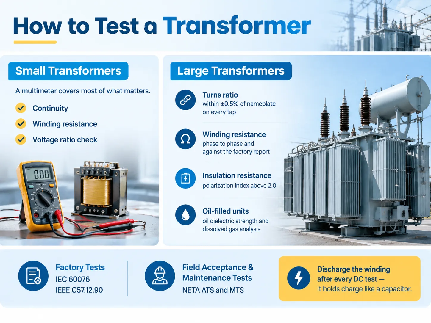
トランスのテストの4種類
テストが実施されるタイミングで分類することは、なぜこれほど多くのテストがあるのかを理解する最も早い方法です。.
| カテゴリー | 目的 | 節約が | 規制参照 |
|---|---|---|---|
| 定期(工場)テスト | 製造されたすべてのユニットの品質管理 | 製造中、すべてのユニット | IEC 60076-1、IEEE C57.12.00 |
| タイプ(設計)テスト | 設計が仕様を満たしていることを証明する | 設計ごとに1回、またはプロトタイプで | IEC 60076-3、IEEE C57.12.90 |
| 特別テスト | 顧客指定の追加証拠 | 要望に応じて | 契約依存 |
| 受入/試運転テスト | ユニットが無傷で到着し、正しく設置されていることを確認する | 初回通電前 | NETA ATS、IEEE C57 |
| メンテナンステスト | サービスライフにわたる状態を追跡する | 定期的、または故障やイベントの後 | NETA MTS、IEEE 62 |
受入テストとメンテナンステストの違いは、見た目以上に重要です。NETA受入テスト仕様(ATS)は、使用前の機器に適用され、同じデバイスの基盤を確立します。メンテナンステスト仕様(MTS)は、使用開始後の同じ機器に適用され、似ているが同じプロセスではありません。テスト自体は似ていますが、結果と目的は異なります。.
試運転のためには、タイムラインを計画する際に知っておくべきもう一つの重要な区別があります: 完了が次のステップにとって重要な異なるステップを持つ試運転チェックリストがあります。ステップを正しい順序で進め、進行中にベースライン値を記録することが、この トランス試運転チェックリスト.
ツールとそれぞれが伝えるもの
| 機器 | テスト | それが検出するもの |
|---|---|---|
| デジタルマルチメーター | 連続性、電圧比、供給チェック | 開放巻線、粗い比率誤差、供給の欠如 |
| 低抵抗オームメーター / マイクロオームメーター | 巻線抵抗 | 緩い接続、断線、悪いタップ接触 |
| トランス回転比(TTR)セット | 回転比と極性 | 誤ったタップ、短絡したターン、開放巻線、誤接続 |
| 絶縁抵抗計(メガー) | IR、PI、DAR | 湿気、絶縁劣化、汚染 |
| 絶縁力率 / タンダルタセット | 散逸係数、静電容量 | 絶縁老化;GST/UST構成におけるブッシング状態 |
| 油試験キット(BDVセル、湿気) | 油の絶縁強度、水分含有量 | 油の汚染と湿気の侵入(液体充填のみ) |
| DGAサンプリング装置 | 溶解ガス分析 | アーク、熱故障、部分放電、セルロース老化 |
| SFRAアナライザー | スイープ周波数応答分析 | 輸送後または通過故障後の巻線変形 |
| クランプメーターとサーマルカメラ | 負荷電流とサーマルサーベイ | 不均衡負荷、熱い接続、冷却問題 |
�¤の事柄について警告する価値があります。トランスが電子保護、雷サージプロテクター、または制御パネルに接続されたままメガーを使用すると、それらが壊れてしまいます。必ず最初に隔離して切断してください!もう1つの事柄は熱検査です — トランスが無電圧の場合、これは何の意味もありません。.
テスト前: 視覚的、機械的および安全
適切に実施された視覚検査の結果として、故障の半分が発見されることが記録されています。.
- プレートと文書。テストプログラムに対して電圧、定格容量、ベクトルグループ、インピーダンス、温度分類、およびタップ設定を確認してください。不正確な名板に対してユニットをテストすると、あなたの一日が台無しになるかもしれません。.
- 物理的状態。輸送損傷、オイル漏れ、ブッシングの損傷、緩い接続、端子ボックス内の湿気、コアブラケットのずれ、故障した圧力計。.
- オイルレベルとオイル充填機器の状態。曇ったり変色したオイルは、それ自体が発見です。.
- 接地とボンディング。タンクのアース接地、中性接地、コアの接地、および関連するボンディングジャンパーの連続性。.
- 隔離とロックアウト。電源を隔離し、ロックとタグを適用し、作業ポイントで死んでいることを確認してください。作業する電圧クラスに応じたアークフラッシュPPE基準はNFPA 70Eによって規定されます。.
電源なしで実行できるマルチメーターテスト
マルチメーターは完全な状況を提供することはありませんが、小型トランスにとって重要な2つの質問に対する答えを提供します: 巻線が開いているかどうか、比率がほぼ正しいかどうか。.
連続性と抵抗。トランスを隔離し、各巻線を個別にチェックしてください。開放の読み取りは、巻線またはその接続に断線があることを示します。抵抗があるべき巻線でのほぼゼロの読み取りは、短絡ターンまたは開放リードがあることを示唆します。降圧トランスでは、一次側は二次側よりもはるかに高いDC抵抗を持つべきです。なぜなら、一次側は細いワイヤーを使用し、より多くのターンを持っているからです。.
電源オン時の電圧比。一次側に定格AC電圧をかけ、ACボルトに設定したメーターで二次側を測定します。一次電圧を二次側で測定した電圧で割ると、名板比が得られます。負荷がないため、巻線のドロップによって読み取りがわずかにずれることがありますが、近い値になるはずです。しばしば、不正確な読み取りは不正なタップにいる、配線が間違っている、またはトランスがラベル通りでないことを示しています。例えば、12 Vのトランスは、120 Vの入力を供給しながら二次側で12 Vを出力するはずです。6 Vまたは24 Vを読み取った場合、あなたは間違った巻線または不正なタップにいることになります。.
マルチメーターができないこと:単一の短絡ターンを正確に特定することができず、絶縁状態を判断することもできません(巻線間の絶縁抵抗をチェックするにはDC電源が必要であり、マルチメーターの低電圧オーム範囲では不十分です)、また、比率をTTRデバイスほど正確に判断することもできません。小型の炉や制御用トランス以上のものについては、マルチメーターは単なる第一歩であるべきです。.
問題がある二つの状況:炉またはHVAC制御トランスの二次側がサーモスタットが呼び出している間に24 V ACを提供するかどうか。負荷の下で失敗する二次側は、トランスの故障ではなく、下流の回路に問題があることを示しています。二つ目の問題のあるケースは、電子レンジの高電圧トランスに関するものです。この場合、最善の方法は、ライブテストを行わないことです。.
ターン比 (TTR)
ターン比テストは、実施できる最も情報量の多い単一テストの一つです。また、現場で最も見逃されるテストでもあります。.
TTRは、巻線の一つに低電圧を印加し、二次巻線に誘導された電圧を監視し、測定された比率を名札と比較します。テストの受け入れ基準はIEEE C57に示されており、すべての巻線で計算値から±0.5%を超えてはならないとされています。.
テストは解釈によって価値を生み出します。.
- すべてのタップでタップステップの割合が同じであれば、機械は間違ったタップに配置されています;これは欠陥ではなく、設置エラーです。
- 一つのタップが外れている場合 — タップリードまたはタップチェンジャー接点に問題があります。.
- 一つの相が測定を欠いており、高い励磁電流があります — したがって、短絡ターンがいくつかあります。.
- 全く読み取りがない場合 — 開放巻線またはリードが断線しています。.
許容範囲外のTTRは、説明がなされるまで通電を許可しません。.
巻線抵抗
巻線抵抗は、DC電流を使用した低抵抗オームメーターを使用して測定され、各巻線を通じて注入され、各相およびタップごとに測定されます。読み取り値はミリオームで示されます。相対的な比較は、相対的に、温度ごとの工場の読み取り値、タップごとの比較が行われます。.
銅の抵抗は温度によって変化するため、すべての読み取り値は比較のために標準温度に調整する必要があります。1度の変化は無視できるが、10度の変化は読み取りを誤って表示する可能性があります。唯一有用な数値は絶対的ではなく相対的であり、すなわち、一つの相が他の相に対して高い場合はその相に接続不良があることを意味し、工場のマークから逸脱した読み取りは接続不良が進行中であることを示します。.
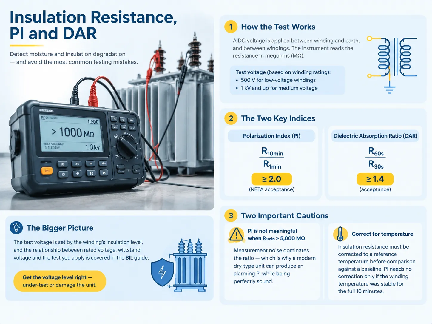
絶縁抵抗、PIおよびDAR
次のテストは、湿気と絶縁劣化を評価することを可能にし、同時に最も誤って実施される可能性の高いテストです。.
絶縁抵抗試験は、絶縁抵抗を測定するために、任意の巻線に対して許容される電圧でDCを使用することに基づいています。通常、低電圧巻線には500 Vの値が使用され、中電圧巻線には1 kV以上が適用されます。現代の固体デバイスはこの作業を容易に行うことができますが、実際の難しさは得られた結果の解釈にあります。.
しかし、実際の重要性は他の2つのパラメータにあります。偏極指数(PI)は、10分間の抵抗値を1分間の抵抗値で割ったもので、受け入れられる最小値は2.0である必要があります。誘電吸収比(DAR)は、60秒間の抵抗値を30秒間の抵抗値で割ったもので、最小値は1.4である必要があります。.
しかし、PIとDARの存在は、いくつかの実用的な考慮事項が無視されると重要性が低くなります。考慮すべき最初の重要な点は、1分間の抵抗値が5,000 MΩを超えるとPI測定が受け入れられなくなることです。これは、測定誤差が結果を支配することはないからです。.
試験電圧自体は巻線の絶縁レベルによって設定され、定格電圧、耐圧、適用する試験との関係は、基本絶縁レベル(BIL)の説明の対象です。 基本絶縁レベル(BIL). レベルを間違えると、ユニットを過小試験するか、損傷を与えることになります。.
耐電圧、部分放電、インパルス
上記の試験は、絶縁がネットワークがもたらすどんな課題にも耐えられることを示しています。これらの試験は工場標準の試験であり、より大きな変圧器の試験を行いたい場合は、さまざまな機器を使用して現場で繰り返すことができます。.
- 電力周波数耐圧試験。試験対象は、特定の試験電圧を特定の時間にわたって受け、電圧は試験値の四分の一から徐々に上昇します。合格基準は、試験中にブレークダウンやフラッシュオーバーが発生しないことです。試験中に使用される基準はIEC 60076-3に規定されています。.
- 雷インパルス試験。試験は、特定の電圧クラスの雷撃を模倣するために1.2/50 µsのインパルスを模倣します。.
- 部分放電測定。試験は、耐圧試験では通常検出できない局所的な絶縁障害のPD測定を行います。通常、新しい変圧器の受け入れ可能な値は、定格相対接地電圧で約10 pCです。.
これらはすべて破壊的な試験です。現場で実施する際に即興を避け、名板に指定された電圧よりも大きな電圧でサービス年数のあるユニットを試験しないでください。.
無負荷、負荷損失、インピーダンス
�¤の試験は、変圧器の設計に関する電気的特性を評価します。.
励磁(無負荷)試験の監視により、1つの巻線に定格電圧が印加され、他の巻線はオフにされ、電圧、電流、および電力の測定が可能になります。誘導電流が高すぎる場合、これは内部回路に短絡が発生したか、コアに故障があることを示唆しています。三脚コアタイプの変圧器の場合、外部の設定の巻線はコア自体の読み取り値よりも大きくなければなりません。そうでない場合、何らかの問題や故障があることを示しています。.
負荷損失とインピーダンスを評価する際、変圧器の巻線は短絡され、電源が定格電圧を供給し、したがって定格電流に達します。計算されたインピーダンスの値は、銘板に示された値と比較され、約±7.5%の偏差が許容されます。これは二次巻線工場から外れないためです。変圧器の実際の使用におけるインピーダンス係数の重要性を強調する必要があります。これは、将来的にデバイス全体の効率に影響を与える主要かつ重要な要素です。.
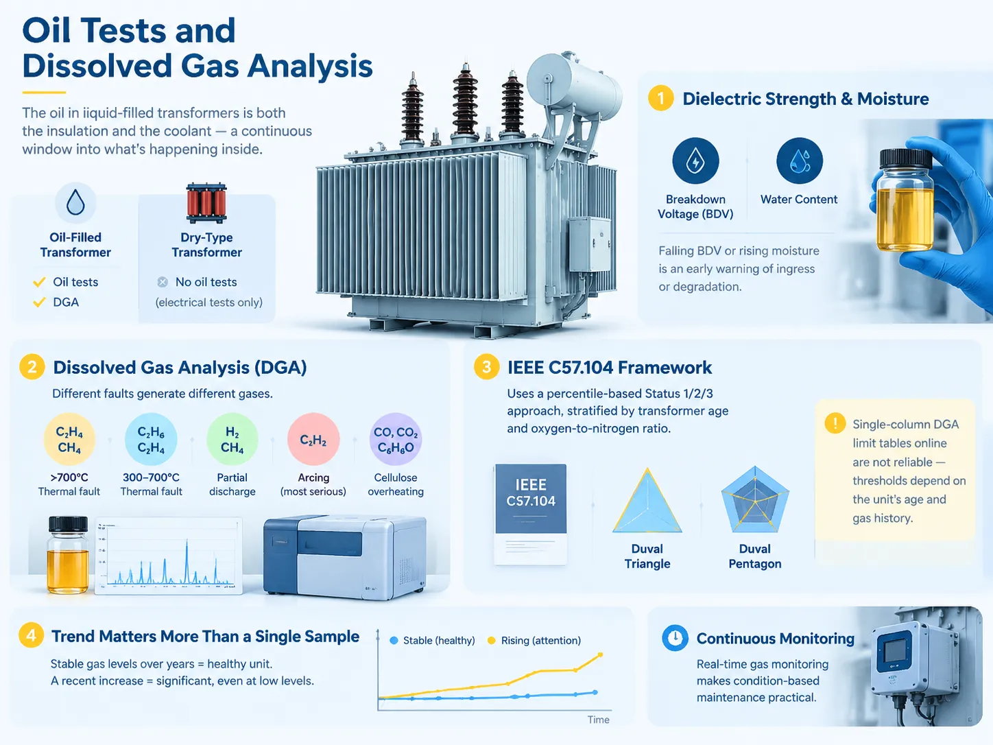
油試験および溶解ガス分析
油-filled 変圧器では、油は絶縁体および冷却剤の両方として機能し、変圧器タンク内で何が起こっているかの恒常的な指標となります。乾式変圧器の場合、油がないため、油試験は行われません。したがって、試験は電気的手段のみに依存します。.
絶縁強度および湿気試験。油試験には、破壊電圧および湿気含量の試験が含まれます。油のBDVが低下したり、湿気が増加した場合、これは変圧器内への水の侵入または油の劣化を示しています。幸いなことに、これらのパラメータは測定が安価です。.
Dissolved gas analysis. DGA is by far the most advanced measure for oil immersed transformers and it works because various faults produce different gases. For example, thermal faults above 700 degrees Celsius generate ethylene and methane; for thermal faults between 300 and 700 degrees Celsius, ethane and ethylene are produced; partial discharge is characterized by the presence of hydrogen and methane while arcing results in generating of acetylene which is known to be a serious indication of the fault; as for overheating of cellulose, it is characterized by carbon monoxide, carbon dioxide and furfural.
Interpretation is outlined by IEEE C57.104 which is currently based on percentiles rather than total combustible gas content. Other methods that can be used include Duval triangle and pentagon. That is the reason why there is no point in using any tables available online in terms of DGA limits, as the limits are determined by the specific equipment’s age and gas history.
Trend is much more important than a single sample. If gas readings are stable for many years, this is a good sign even if the values are high. On the contrary, increase in readings is alarming even if the readings are not high. This is the reason why the testing should be done on a regular basis and compared to previous data during each testing.The monitoring practice that makes this practical, including continuous gas monitoring instead of periodic sampling, is described in this overview of real-time transformer gas monitoring for condition-based maintenance.
Polarity, Vector Group and Phasing
This testing will show that the transformer has been hooked up in accordance with the information given on the nameplate, ensuring safety of parallel operation. The single-phase polarity test is used to determine whether the winding is of additive or subtractive polarity. The three-phase phase relation test confirms the vector group and phase sequence of the transformer. Mismatching polarity or vector groups of two transformers being operated in parallel results in the generation of a current that is strong enough to burn both transformers. Hence, this is a critical stage of commissioning.
Reading the Numbers: Pass, Investigate or Stop
| テスト | Typical acceptance | Investigate | Stop and diagnose |
|---|---|---|---|
| Turns ratio (TTR) | Within ±0.5% of nameplate, all taps | Any consistent deviation | Single phase off, or no reading |
| 巻線抵抗 | Balanced phase to phase, matches factory report | A few percent spread | One phase clearly high or drifting |
| 絶縁抵抗 | Above the baseline for the class | Falling trend against previous tests | Below the minimum for the voltage class |
| 偏極指数 | ≥ 2.0 | 1.5–2.0 | Near 1.0 (unless 1-minute IR exceeds 5,000 MΩ) |
| インピーダンス(%Z) | Within ±7.5% of nameplate | Modest deviation | Large deviation — likely winding deformation |
| DGA | Status 1, stable trend | Rising trend or Status 2 | Acetylene present, or Status 3 |
| Oil BDV | Above the specified minimum | Falling against baseline | Low enough to compromise insulation |
What should be done when the tested unit failed is to explain why it failed instead of making a judgement about it. If a unit shows excessive ratio because a wrong tap was used, it can be fixed in five minutes. If a dry-type unit shows somewhat low PI while possessing very high IR value, it indicates the presence of measurement noise, not degradation.Diagnostic discipline at this stage is what stops a serviceable transformer being scrapped on the strength of one number, and the systematic route through the common failure modes is set out in this guide to troubleshooting power transformer faults.
How the Test Battery Changes by Transformer Type
The basic electrical tests are universal. The only thing that changes is the details and the stress given.
- Distribution transformer (with oil). The entire battery of electrical tests plus oil BDV, moisture and DGA. The standard tool for roadside and pit-type transformers
- Dry transformers. The same battery of electrical tests but without the oil tests. For dry-type machines, the procedures are automatic and described here in the dry-type transformer routine tests description. PD measures are quite significant because there is no oil to test.
- Large power transformers. In addition to all the electrical tests mentioned above, the insulation power factor test (in GST, GSTg, UST versions), capacitance test, bushing power factor test against nameplate C1 parameter; SFRA method for everybody will be added.
- Instrument transformer. Ratio and polarity checks, and also accuracy class testing are to be performed according to their own standards, not according to that of the large power transformers.
- Small and single-phase transformers. Simple tests are usually enough: continuity test, resistance test, ratio test, voltage test.
Safety Rules That Are Not Optional
Discharge after every DC test. TTR, insulation resistance and power factor tests all charge the winding and a winding retains this charge, like a capacitor, after disconnection. It must be grounded using a grounding stick immediately after testing and kept grounded until next step. This is how technicians can get shocked by a deactivated meter.
Prior to carrying out any resistance or continuity measurement isolate and lockout. The meter can be destroyed, and operator can be hurt if an ohmmeter is used on a powered circuit.
Unplug surge protectors, protective relays, and control circuits before testing insulation resistance. High voltage will damage them.
PPE must correspond to the voltage class according to NFPA 70E standards and the results of the arc flash study conducted at the facility, not to the tradition.
よくある質問
How to test if a transformer is working?
To check a smaller transformer, first isolate it, conduct winding continuity checks and DC resistance measurements on it using a multimeter, and then apply the rated AC voltage to its primary side and verify that the secondary side reads almost the rated voltage on it. For larger transformers, the passed field check consists of a turns ratio test on every tap that is within ±0.5% of nameplate specification, insulation resistance measurement yielding a polarization index higher than 2.0, and visual and thermal inspections under load. In case of oil-filled transformers, the boil dielectric strength test and dissolved gas content test are also required. The term “working” means that all said above have passed rather than the secondary having some kind of voltage on it.
What are the methods of testing a transformer?
There are prominent electrical methods including turns ratio (TTR), winding resistance, insulation resistance using polarisation index and dielectric absorption ratio, insulation power factor or tan delta, applied voltage (power frequency withstand), lightning impulse, partial discharge, excitation or no-load loss, load loss with short-circuit impedance, polarity and phase relationship etc. In terms of mechanical or chemical methods, SFRA and oil dielectric strength moisture testing and dissolved gas analysis can be used for transformers. The choice of method depends on the type of transformer, size and stage of its life.
How to test a 12V transformer with a multimeter?
Make sure that the transformer is disconnected from loads. Set the meter to ohms and measure the resistance across the primary: it must show positive resistance, not an open circuit and its value should be greater than that of the secondary winding since the latter usually consists of thicker wire and has fewer turns. If the transformer can be used with mains supply on the primary, supply the transformer with the rated voltage and measure the secondary voltage with the meter set to the AC volts — the meter must read close to 12 Volts without load and may show a little higher voltage. If the readings are half or double the expected value, the readings have been taken from some other winding. Do not connect mains to the transformer if its primary circuit rating is unknown.
How to test a transformer with a multimeter without power?
Checking continuity and DC resistance without power only is possible. Using the two meters you need to check winding by winding. If your reading is infinite ohms, you have an open circuit problem in the winding or lead. If the reading is almost zero while in winding having considerable resistance, you have a short circuit. By comparing primary and secondary resistance, you can figure out whether the unit is step-down transformer and how it is wired in general. However, you cannot establish turns ratio, insulation resistance between the windings or locate a single shorted turn.
How to test a transformer with a megger?
The next step is to isolate the transformer as completely as possible. Disconnect the surge arresters, protection relay and control electronics first. Decide on the test voltage for winding insulation class — low voltage windings have 500 V DC, and medium voltage has 1 kV or higher. Winding to earth is measured first, and then winding to winding. Ensure the test is conducted for the full duration — don’t just read the needle right away. Polarization index is obtained from the reading done after 1 min and 10 min; NETA acceptance is above 2.0, dielectric absorption ratio is above 1.4. Also remember to adjust your raw insulation resistance for temperature before comparing it with the baseline values.
Can I test a transformer without disconnecting it?
Although it is possible to apply ratio and continuity tests to a circuit that has been disconnected, in the case of insulation testing, the insulation resistance test applies a high voltage direct current which results in damaging any equipment that may be connected. Thus the disconnection of the circuit is not simply a procedure but a necessary prerequisite for making such tests valid.
参考文献
- International Electrotechnical Commission — IEC 60076シリーズ、電力トランス
- IEC Webstore — IEC 60076-15, Power transformers, Part 15
- IEEE Standards Association — IEEE C57.12.90 test code, IEEE 62 field diagnostics, IEEE C57.104 DGA
- UL Standards & Engagement — UL 1562, Transformers, Distribution, Dry-Type
- UL Solutions — transformer and electrical equipment testing services
結論
The tests on a transformer follow a specific order, and it is this order that makes them dependable. First comes the visual inspection, and then comes the dead tests followed by the live tests, with the winding always discharged after each DC test and all measurements taken and kept as reference.
When it comes to transformer testing, there are essentially three points that must be taken into consideration. A transformer needs to be tested according to its specific characteristics. A control transformer would need only a multimeter and a turns ratio test kit while a 1MVA transformer would require equipment that is completely different from that. A qualitative comparison of the data should be done, rather than relying on some absolute figures — the turns ratio should be within ±0.5 percent of the nameplate reading, winding resistance should be well balanced among phases and must match factory specs, and PI should be above 2.0 only to realize that at higher resistance levels this indicator has little or no meaning anymore basically.
Moreover, the tests need to be conducted in a specific order making sure to record everything and discharge the winding after each and every DC test. The majority of transformer issues are visible way before they actually happen.