


Un trasformatore di corrente (CT) è un dispositivo utilizzato con un sistema di misurazione/protezione per misurare grandi quantità di corrente/valori che non sono direttamente misurabili; converte la corrente da 400, 1000 e 3000 A in un valore utilizzabile di 5 o 1 A. Questa modifica avviene sotto determinate condizioni che devono essere seguite dal dispositivo CT: la polarità deve essere corretta, il carico deve essere accurato, il cablaggio secondario non deve mai essere esposto a un circuito aperto mentre la corrente è in flusso. Il manuale include specifiche riguardanti il collegamento del cablaggio dei CT con dispositivi di misurazione, relè e monitoraggio, come impostare il cablaggio passo dopo passo e il modo in cui i modelli trifase devono essere cablati.
Nel caso in cui la corrente primaria o il conduttore collegato al dispositivo possa essere fatto passare attraverso il trasformatore P1 e P2, allora la lettura registrata ai terminali secondari P1 e P2 potrebbe essere errata a causa del fatto che S1 potrebbe non corrispondere a P1 in tutti i casi, portando a una lettura di tensione della corrente ai collegamenti S1 S2. Quando si utilizza un singolo trasformatore, sia i collegamenti S1 che S2 non vengono utilizzati rispetto a tutti i collegamenti trifase. Non c'è alcun requisito per un altro metodo di collegamento se si utilizza un singolo CT poiché sarà sempre un collegamento diretto per i due di S1 e S2. In caso di cablaggio trifase, il trasformatore deve essere collegato utilizzando il metodo di collegamento “Y” o a stella con S1 collegato ai tre ingressi strumentali dove l'uso dei collegamenti S2 avviene nel punto di unione dove S2 sarà collegato al punto comune a stella indipendentemente da uno dei due metodi sopra utilizzati.
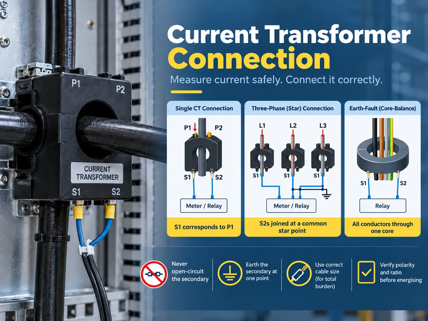
Cosa fa un trasformatore di corrente e perché il collegamento è importante
I CT sono trasformatori specializzati che possono funzionare solo in un modo: prendendo la corrente primaria e producendo una corrente secondaria proporzionale garantendo l'isolamento dal circuito primario. Un CT 400/5 produce cinque ampere al secondario quando il primario ha una corrente elettrica di 400 ampere. Inoltre, fornisce due e mezzo ampere a carico parziale, e il misuratore o relè collegato interpreterà queste informazioni e le riporterà al primario.
| Tipo di CT | Costruzione | Uso tipico |
|---|---|---|
| CT a barra primaria (finestra) | Il primario è una barra fissa o il busbar passa attraverso la finestra | Apparecchiature di manovra, misurazione del pannello, retrofit attorno a barre esistenti |
| CT a primaria avvolta | Il primario è un avvolgimento portato ai terminali (P1/P2) | Applicazioni a basso rapporto e a rapporto speciale |
| CT a nucleo diviso | Morsetti attorno a un conduttore esistente senza disconnessione | Monitoraggio energetico retrofit, sub-misurazione |
| CT a boccola | Integrato in una boccola di trasformatore o interruttore | Protezione di trasformatori e apparecchiature di manovra |
| CT a bilanciamento del nucleo (zero-sequence) | Tutti i conduttori di fase passano attraverso un nucleo | Rilevamento di guasti a terra e misurazione di perdite sensibili |
Ci sono due fattori importanti che mostrano come un CT dovrebbe essere collegato. Il rapporto per la corrente secondaria indica quanta corrente il CT fornirà per una certa corrente primaria (ad esempio 400/5 o 1.000/1). Il carico in VA indica la quantità di carico (misurazione e relè) che deve essere collegata al CT senza influenzare le sue prestazioni. Pertanto, se un CT funziona secondo il corretto rapporto ma è caricato in modo improprio, le letture non saranno accurate.
Terminali e polarità: P1, P2, S1, S2
I terminali del CT seguono una convenzione stabilita secondo cui il cablaggio è sempre inequivocabile una volta comprese le etichette:
| Terminale | Significato | Regola di connessione |
|---|---|---|
| P1 | Lato primario, contrassegnato da polarità | Di solito è rivolto verso la sorgente (il lato in arrivo del conduttore) |
| P2 | Lato primario, non contrassegnato | Rivolto verso il carico |
| S1 | Secondario, corrisponde a P1 | Si collega all'ingresso dell'apparecchiatura contrassegnato S1 (o all'ingresso “linea”/polarità) |
| S2 | Secondario, corrisponde a P2 | Si collega all'ingresso dell'apparecchiatura contrassegnato S2, o al punto stella/comune negli schemi trifase |
La regola di polarità è una delle principali fonti di errori di messa in servizio. Poiché S1 deve sempre corrispondere all'ingresso S1 dell'apparecchiatura, e P1 con la sorgente, un cambiamento nell'orientamento del CT o nel collegamento da S1 a S2 causerà l'inversione delle correnti misurate. Le applicazioni di protezione sensibili alla direzione possono fallire così come le letture di potenza (kW) in cui l'importazione può apparire come esportazione. D'altra parte, K e L come contrassegni possono essere utilizzati da alcuni produttori, il principio rimane lo stesso (K deve corrispondere a P1 e L a P2), il che significa che la targhetta deve dettare il cablaggio e non il modo di vita.
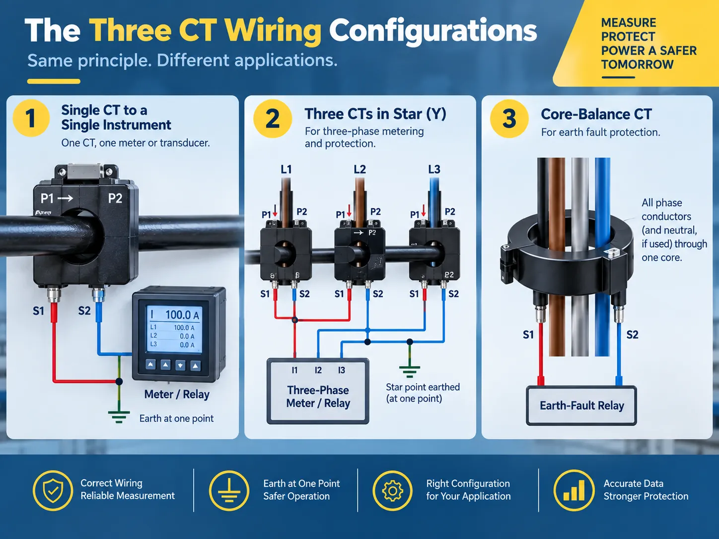
Le tre configurazioni di cablaggio che utilizzerai effettivamente
Quasi ogni installazione di CT è suddivisa in tre tipi di configurazione:
- Un CT utilizzato in combinazione con un singolo strumento. Un CT con un misuratore o sensore: S1 è collegato a S1 dell'apparecchiatura, e S2 è collegato a S2 dell'apparecchiatura, mentre il lato secondario è messo a terra in un punto (di solito al pannello dell'apparecchiatura). Questo è il modo standard di utilizzarlo per un pannello di alimentazione dedicato o per il monitoraggio della corrente del motore. La stessa procedura viene ripetuta tre volte nel caso di misurazione trifase a quattro fili.
- Utilizzo di tre CT in una configurazione a Y per misurazione e protezione trifase. Qui, tutti e tre i fili S1 sono collegati all'ingresso di corrente corrispondente dell'apparecchiatura, mentre tutti e tre i fili S2 sono portati a un unico punto stella. Questo punto stella è il punto in cui il secondario è messo a terra. La configurazione a stella è utilizzata come configurazione predefinita per i misuratori di energia trifase e i misuratori di potenza poiché fornisce una copia accurata delle correnti di fase e offre anche un percorso per gli squilibri di corrente.
- Un CT a bilanciamento del nucleo è utilizzato per la rilevazione di guasti a terra. In questo caso, tutti e tre i conduttori di fase (e il neutro, a seconda dell'applicazione) vengono fatti passare attraverso un unico nucleo del CT. In condizioni normali, la somma vettoriale delle correnti è pari a zero, e quindi il secondario del CT legge zero; qualsiasi guasto a terra porta a una certa corrente che ritorna attraverso la terra invece che attraverso il neutro e produce un segnale residuo che viene rilevato dal relè di guasto a terra. Il cablaggio è meno complicato in questa configurazione (solo due fili secondari vanno al relè), ma devono essere rispettate alcune regole fisiche: non possono passare altri fili attraverso il nucleo, e la schermatura o l'armatura del cavo non possono creare un percorso parallelo che annulla la corrente residua.
Se lo stesso CT deve fornire dati sia per un misuratore che per un relè di protezione, allora i due carichi sono cablati in serie (il misuratore per primo, poi il relè, o utilizzando nuclei alternativi se il CT ha più secondari) e non in parallelo o con nuclei non utilizzati. La filosofia di protezione dietro le connessioni residue è spiegata ulteriormente nella nostra basi della protezione da guasti a terra guida.
Il diagramma di connessione del CT, spiegato
Si deve leggere uno schema di cablaggio del CT partendo dal lato primario e terminando all'istrumento. Questo è un esempio di come apparirebbe un'installazione di misurazione trifase quando presentata in un diagramma:
| Da | Per | Conduttore |
|---|---|---|
| Phase A conductor (source side) | CT-A P1 | Primary circuit — not CT wiring |
| CT-A S1 | Meter current input IA (S1) | 2.5-4 mm² copper, 600 V rated |
| CT-A S2 | Star point | Same size as S1 |
| CT-B S1 | Meter current input IB (S1) | Same size |
| CT-B S2 | Star point | Same size |
| CT-C S1 | Meter current input IC (S1) | Same size |
| CT-C S2 | Star point | Same size |
| Star point | Earth (one point only) | Grounding conductor per local code |
| Each S1/S2 pair | Shorting/test terminal block | Installed between CT and instrument |
If your project has a supplied wiring diagram, it should be used as the primary source document. However, all of the following three conventions should be used to verify it before you finalize the installation: use of S1 to S1 pairing, use of a single earth point, and presence of a shorting mechanism in the circuit. Any discrepancies in these three aspects can lead to improper commissioning and create unsafe conditions.
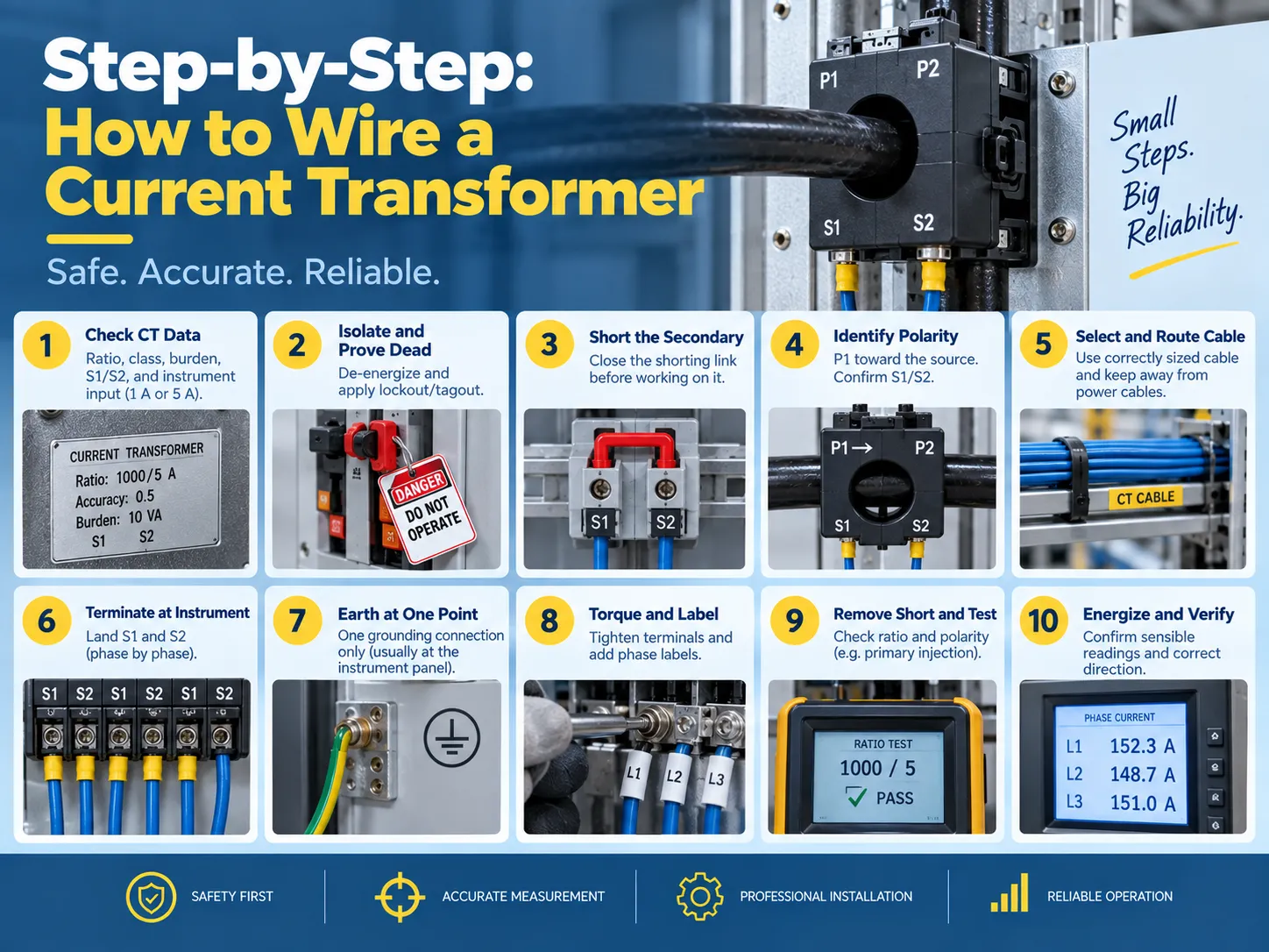
Step-by-step: how to wire a current transformer
- The first step is to verify the CT data and check the instrument demands. Check the nameplate for the ratio, accuracy rating, burden (VA), and polarity markings. Confirm the input rating of the instrument (1 A or 5 A) is consistent with the CT secondary because if a 5 A CT is connected to a 1 A input, the instrument will read inaccurately by a factor of five and may saturate the input.
- The device must be isolated, followed by the verification of the dead condition. The primary circuit must be de-powered, and proper lockout/tagout measures must be applied. It is important to remember that “even if the primary circuit has been isolated, there may still be a live CT secondary that is energized from another source” and hence it is important to consider every CT circuit live until proven otherwise.
- The next step is to short the secondary circuit. The shorting link on the testing terminal block needs to be closed or a proper shorting device may be used to connect S1 and S2. This procedure eliminates the danger of CT failure.
- The next step is to find the polarity that involves locating the points P1 and P2 of the primary as well as S2 and S1 for the secondary. It is essential to confirm that the primary orientation (where P1 points toward the source) and the physical arrangement matches the diagram.
- Select the proper secondary cable. Copper conductors of the appropriate size need to be used for both the burden and run length (standard 2.5 mm², 600 volts) with the goal of avoiding running power conductors in the sheath while achieving all three phases.
- Termination needs to happen at the instrument with S1 in the S1 (polarity) input on the instrument and S2 on the second input.
- Ensure that there is a grounding at only one point, typically at either the instrument or relay panel.
- Check the terminals for torque settings according to the manufacturer and apply labels to the phases including the ratio label.
- The shorting link must be removed before testing commences with the verification of the ratio and polarity.
- Turn the energizing circuit on so the circuit is reading correctly on the instrument with all three phases being noted at the current reading.
Burden and cable sizing: the calculation most installers skip
Current transformers (CTs) have a rated burden above which they will not be accurate. The burden total includes all devices connected to the secondary and the resistance of the secondary wiring:
- Instrument burden: this is the VA burden (or ohmic) specified by the manufacturer of the meter or relay. It can vary by instrument type, but is generally in the range of 0.2-1 VA per current input for modern electronic instruments and higher burdens for older electromechanical relays.
- Wiring burden: the wiring resistance is calculated as follows: 2 x one-way length x resistance per meter (for example, the resistance for 2.5 mm2 copper wiring is approximately 7.4 ohm/km), times the square of the secondary current. Depending on the run length, it is not uncommon for the instrument burden to be exceeded simply due to wiring burden.
- Connection burden: the resistance across the terminals and test blocks is generally small, but if the wiring total is close to the CT burden, this value should be included.
If the total burden exceeds the rating of the CT, it cannot provide accurate readings and may saturate during fault currents – which is when protection is needed most. Possible remedies include a shorter cable run, a larger conductor, using a lower-burden instrument, or buying a CT with a higher VA rating.
The accuracy classes themselves — 0.5 and 1 for metering, 5P and 10P for protection — are explained in our transformer accuracy classes guide.
And the ratio-selection logic for a given installation, from load current and fault level to the final nameplate choice, is covered in our current transformer ratio selection articolo.
Testing and verification
Three tests are used to ensure that a CT is installed correctly before it is allowed to carry load:
| Test | What it proves | Metodo |
|---|---|---|
| Ratio test | The CT produces the expected secondary current for a known primary current | Primary injection at a fraction of rated current, or a secondary-voltage method for large CTs |
| Polarity test | S1 truly corresponds to P1 and the instrument reads forward power correctly | DC pulse or primary injection with a polarity-sensitive instrument |
| Insulation and continuity | No shorted or open secondary conductors, and adequate insulation to earth | Insulation resistance and continuity checks before energization |
Post-energization verification is equally important because you should compare the readings of the CT with a reading from a clamp meter on the primary side, verify that the readings are consistent across all three phases, and confirm that the earth-fault circuits register zero residuals on a healthy feeder.Where the CT is part of a protection scheme, that coordination — and the grounding references it depends on — is the subject of our basi della messa a terra dei trasformatori guida.
Safety rules, and the mistakes that damage equipment
The secondaries of current transformers only flow small amounts of current at low voltages—until something goes wrong. The following are mandatory guidelines for dealing with current transformer circuits:
- Never open the current transformer circuit secondaries while the primary circuit is energized. The current transformer will attempt to generate very high voltages (hundreds or thousands of volts) across the secondary terminals when it is open, leading to an extreme overvoltage situation, core saturation, overheating, and potentially explosion and fire.
- Ground the current transformer secondary only at one point. Connecting the ground at two points will cause unnecessary current to circulate through the ground contributing to an incorrect measurement and potentially causing an unnecessary trip of protection equipment.
- Avoid installing a switch or fuse in the current transformer circuit that is not a shorting type of test block. Standard circuits may fail open which creates the same condition as an open circuit.
- Do not leave spare current transformer cores open. Short the unused coils and note them on the drawing, or future technicians may be incorrectly leading service personnel to assume that they are open circuits.
- Be sure to observe proper polarity at each connection. The S1-to-S1 and P1-to-source connections are not arbitrary conventions that may be changed later.
- Keep current transformer wires away from power and variable frequency drive (VFD) cables, and do not pass the current transformer around just a single part of the conductor in a core balance scheme.
Two other practical points to remember are that a current transformer must be hooked up with the instrument input rating matching the transformer’s secondary rating (either 1A or 5A) and that the primary conductor must pass through the window in one direction only. Passing a bar or cable back through the core backwards will reverse the effective polarity of the current transformer.For meters that must be removed for calibration, the test block should be the type that automatically shorts the CT when the instrument is unplugged; the wiring practices around metering and instrument transformers are also covered in our current transformer installation guide.
FAQ
What are the disadvantages of using a current transformer?
There are several drawbacks; having an open-circuit secondary is dangerous since it creates the possibility of serious injury; calculation of the connected load must be done correctly, or else inaccurate readings will be produced; incorrect polarity can result not only in inaccurate readings but also in malfunctioning protection devices; there is a small phase shift introduced by the CT that results in a slight inaccuracy in measurements; added expense and panel space; proper sizing is necessary, otherwise, the CT will saturate during a fault condition. Although modern electronic meters do reduce some of the problems associated with these drawbacks, all of them cannot be eliminated.
How are current transformers wired?
To connect the primary conductor through the CT there is P1 (the source side) and P2 (the load side) or the line is passed through the bar / window. The secondary side will be S1 and S2 with S1 corresponding to P1. The S1 and S2 will lead to either a meter, relay, or transducer directly for a single CT or in a star configuration for three-phase metering (three S1s to the meter and three S2s coupled to one grounded star point, etc.). There is a shorting/test terminal block mounted at the juncture of the CT and the instrument.
Does it matter which wire goes where on a transformer?
For any transformer it does; however, CTs have unique requirements. This is due to the leads having a specific polarity (i.e., S1 correlating to P1). By reversing these two leads, it causes current to flow in the opposite direction creating inaccurate power readings along with the possibility of malfunctioning protection devices. This is applicable in both transformers with respect to the primary and secondary leads.
How do you connect an electrical transformer?
In the case of an instrument transformer such as a CT: verify the ratio and the burden, isolate the transformer and prove it to be dead, short out the secondary side, identify which lead corresponds to P1 and which lead corresponds to S1; connect the correctly sized secondary cable such that S1 and S2 lead to the instrument’s respective inputs, ground the secondary at one point, label and torque the connection, remove the ground; and finally inject a known standard into the system to verify polarity and ratio. The process for connecting a power transformer differs from this procedure but still requires the individual to verify ratings, polarity, grounding, and testing before energizing load.
Riferimenti
- IEEE — C57.13, Standard Requirements for Instrument Transformers
- IEC — 61869 Series, Instrument Transformers
- NFPA — National Electrical Code (Instrument Transformer Circuits)
- NETA — Acceptance Testing Specifications for Electrical Power Equipment
Conclusione
The installation of the current transformer carries a lot of weight although it may seem like an unimportant task. The function of the current transformer is to reduce the amount of primary current flowing through the wire to a safe reading for the meter or relay. Therefore, you can see how important this task is in the long run. For the primary wire (P1) you will have to run wire to the source while the secondary wire (S1) will run from the current transformer to the meter or relay. If you are wiring three-phase meters, the circuits must be wired in a star pattern and grounded at a single point to earth. Use a core-balance CT for residual currents; make sure you size the secondary wire appropriately according to the burden load. Always use a test block to short out the circuit before energizing it and never break the circuit as long as current is flowing through the primary side. Make sure that you check the readings first using primary injection and then record the ratio on the sheet for future reference.