


While the 45 kVA transformer is probably the most widely used size of transformers for the small commercial and light industrial sectors, it is also where many people fail because of the question of the actual current hands. The answer would depend upon which part of the transformer is looked into, what voltage is used, and what connections are made. To explain this in the order of a real-time project, first the formula will be presented, and then it will be followed by a complete current table, the case of 480 volts going down to 208 volts and other accessories, and then finally by common mistakes in implementation
A 45 kVA transformer when connected in a three-phase system will deliver a current of 54.1 A at 480 V, 124.9 A at 208 V, 108.3 A at 240 V and 43.3 A at 600 V. Its power will run at a voltage of 240 V in single-phase circuit at current of 187.5 A (just as at 120 V, producing 375 A). All the results can be obtained according to such formulas: amps = kVA x 1,000 / L-L V for balanced three-phase systems, amps = kVA x 1,000 / V for single-phased systems. In other words, if we take a step-down transformer that has 480-208 V connections, its primary voltage will produce current of 54.1 A while the secondary voltage will generate current of 124.9 A, that is for lower voltage there is always a higher current.
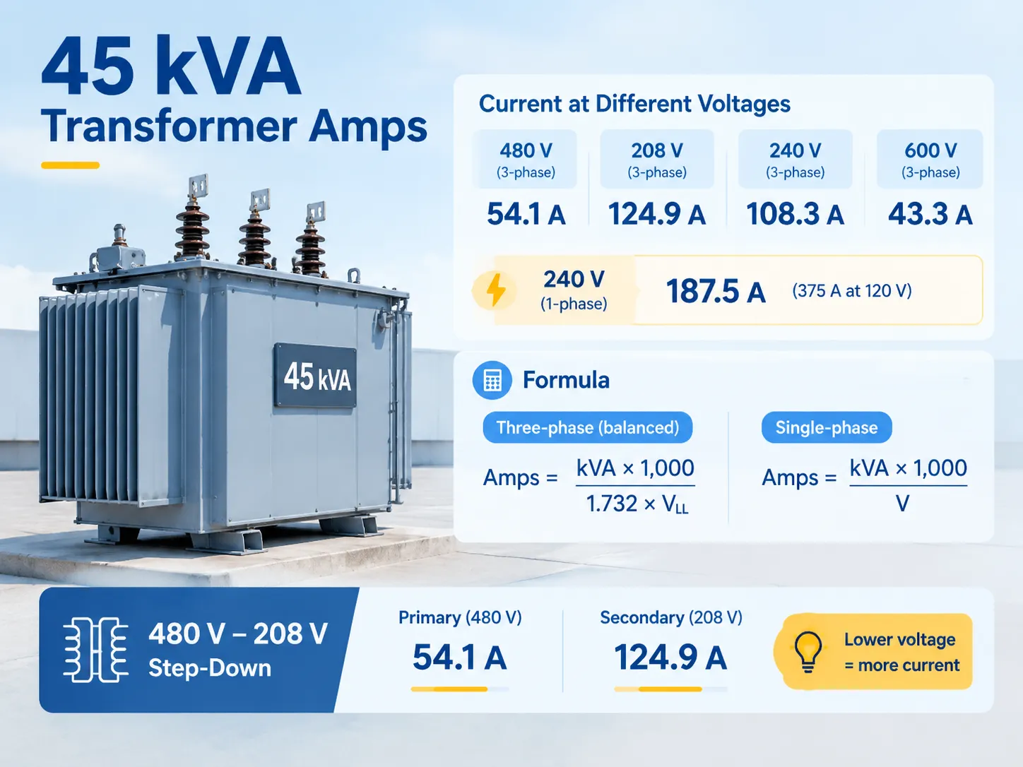
The only formula you need, and the assumption hiding inside it
In a balanced three-phase load, line current is given by the formula: I = kVA × 1,000 ÷ (√3 × VLL), where √3 = 1.732.
In the case of a single-phase load, no √3 is needed: I = kVA × 1,000 ÷ V.
Two assumptions are at play here, both of which must be right before it can take any meaning. First, it is vital to remember that voltage in the formula must be the line-to-line voltage — for example, using 277 V (line-to-neutral for 480Y/277) instead of line-to-line voltage is one of the most common mistakes in calculations. Second, remember that kVA corresponds to apparent power, and thus does not take power factor into account. If your piece of equipment asks you for power factor during a kVA to amp calculation, it is committing an improper operation. Power factor only enters when you are converting kW (real power) to amps, and it is that kW-versus-kVA distinction that trips people up when they compare a nameplate against a utility bill — the same distinction that runs through トランスのサイズ設定と負荷計算 for anything other than a resistive load.
Full-load current table: 45 kVA across standard voltages
Here is the overall understanding. These currents are based on nameplate value, not on actual measurement; and assume the load being balanced.
| System voltage and phase | 定格負荷電流 | Where you see it |
|---|---|---|
| 480 V, 3-phase | 54.1 A | Primary side of a 480–208 step-down; industrial distribution |
| 400 V, 3-phase | 65.0 A | IEC networks, export equipment |
| 380 V, 3-phase | 68.4 A | Older IEC networks |
| 600 V, 3-phase | 43.3 A | Canadian and some industrial systems |
| 240 V, 3-phase | 108.3 A | Delta systems, small commercial |
| 208 V, 3-phase | 124.9 A | Secondary of a 480–208 step-down; commercial panels |
| 240 V, 1-phase | 187.5 A | Single-phase service, some light commercial |
| 120 V, 1-phase | 375.0 A | Rarely practical at this rating; shown for comparison |
The table must be treated as a proportion problem rather than a series of numbers. When one decreases voltage by half, current automatically increases by two times, which makes the 120 V column seem frightening, where 45 kVA cannot be distributed at such voltage. Furthermore, when one moves from single phase to three phase, the current is divided by 1.732, therefore making a 45 kVA three-phase transformer seem much smaller per each leg than the single-phase transformer does.
The 45 kVA 480-to-208 case, side by side
This is the configuration most people are actually asking about, so it deserves its own treatment.
| パラメータ | Primary (480 V, 3-phase) | Secondary (208Y/120 V, 3-phase) |
|---|---|---|
| 定格容量 | 45 kVA | 45 kVA |
| Full-load line current | 54.1 A | 124.9 A |
| Continuous-load basis (125%) | 67.6 A | 156.1 A |
| Typical protection | 70 A | 175 A |
| Typical copper conductor (75°C terminations) | 4 AWG | 2/0 AWG |
As a result, two consequences arise. For one, the secondary side causes your conductor cost to have a more significant impact; most of your 45 kVA making its way through a lower voltage means that the current level increases by 2.3 times, and thus the copper necessary for the wires should grow. Furthermore, the protection ratings of the primary and secondary sides are not two variations of the same apparatus but the results of two different calculations made according to two different parameters.
In this case, the 45 kVA unit is most likely a dry-type transformer as it is situated inside a room next to the load in a closet or machine room. If you are comparing construction types for a specific installation, the practical differences in enclosure, cooling, insulation class and where each type can legally be installed are covered in the dry-type transformer specification range — and the choice genuinely changes the footprint, the heat load you are dumping into the room and the maintenance regime.
Conductor sizing: where 54.1 A becomes a real wire
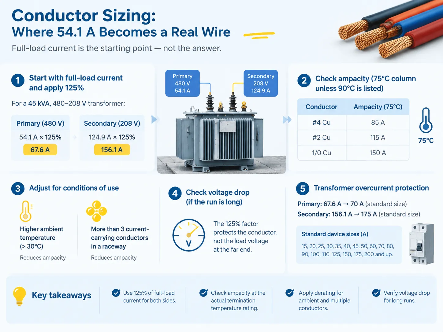
While full-load current is the starting point, it is not the answer. The conductor sizes selected for transformer circuits are typically not less than 125% for both the primary and secondary conductors. After this step, the conductor sizing should meet the ampacity rating of the conductors at the actual termination temperature.
- Initiate with the full-load current for the side being investigated (54.1 A for primary and 124.9 A for the secondary on a 480-208 unit).
- Use the 125% factor to compute 67.6 A and 156.1 A.
- Pick a conductor from the corresponding ampacity column, preferably 75°C unless it is known that the termination can be done at 90°C.
- Make necessary adjustments for use conditions. Weather temperatures over 30 °C and more than three conductance wires in a raceway will decrease the effective ampacity therefore a conductor which may look to be adequate on paper could be, in real life, too little.
- Make sure to check voltage drop in anticipation of long runs. The 125% ampacity factor will protect the conductor but it provides no guarantee that the load will be receiving enough voltage.
Both of those derating factors are exactly the kind of thing that gets skipped when someone sizes from a chart instead of from the installation. Elevated ambient is not hypothetical either — a transformer closet in a plant is often the hottest space in the building.
Protection sizing under the transformer rules
The process of protecting transformers from overcurrent function according to its own specifications. The common rule concerning transformers with primary currents of 9 A and more is that the control level should not exceed 125% of the primary rated current and the secondary protection should not exceed 125% of the rated secondary current—you will find a variety of standard sizes such as 15A, 20A, 25A, 30A, 35A, 40A, 45A, 50A, 60A, 70A, 80A, 90A, 100A, 110A, 125A, 150A, 175A, 200A, etc.
In case of a 45 kVA transformer operating at 480 V at the primary point, the calculated value will give us approximately 67.6 A, which means that we can use a 70 A transformer. When evaluating the 208 V level, we will get the value of 156.1 A, which leads us to using 175A. Please note that if the calculated value of 150 A lower than the required value, this will only be possible if we use the transformer of the next up size, which doesn’t exceed the required numbers. In this case, we should also consult with the authorities in charge concerning this device and implement their suggestions.
Another requirement is that the unit should be able to withstand the level of fault current on its connection point, which in the case of the small transformer of 45 kVA will not be a problem for the secondary connection but may cause a lot of difficulties for the primary one due to the stiffness of the service. In case if the breaker does not have enough interrupting rating, this means that it works not as intended, which is likely to lead to transforming the accident into an arc event, if it gets fail.
Inrush current: why the breaker sees ten times 54.1 A
Energising a transformer causes the core to go into saturation during the initial few cycles. The level of saturation could result in magnetising inrushes of anywhere between 8 to 12 times the rated current, which can exceed that level in some transformer designs. The magnetising inrush dies down after a few cycles of operation up to a few second. This is a normal phenomenon; it is not a fault.
This is important for practical reasons. Firstly, it plays a role in explaining nuisance trips that occur at energisation when a thermal magnetic device with a low instantaneous setting is selected based solely on the steady state current. Secondly, it leads to the fact that an individual should not upsize the branch protection in order to prevent nuisance trips; instead, it is best to select a device which has a certain magnetic or instantaneous characteristic that will withstand magnetising inrush while continuing to protect the circuit during its operation. One of the most common mistakes with this aspect is oversized circuit breaker because it may turn the protection away from the necessary position in more than 200 milliseconds after energising the transformer.
The 80% rule, and what it is really describing
The statement “make sure to run the transformer at eight percent rated load” is often treated as some sort of code. The code, in fact, is the continuous-load rule, which information states that a load can be considered continuous upon operating for three hours or more. Such load is even multiplied by 125%. It is this percentage that corresponds to 80% load of transformer that it can serve continuously.
If we take a 45 kVA transformer, for example, 80% will yield the value of 36 kVA of continuous load, which at the voltage of 208 takes approximately 100 A. It is always better to stay well below this mark while working with dry-type transformers in hot electrical rooms, as this ensures maintenance of the right temperature conditions and prevents rapid ageing of the insulation.
Reading the nameplate before you pick conductors
The present only refers to a single line on the nameplate, while the remaining lines alter the contents.
| Nameplate item | Why it changes your decision |
|---|---|
| kVA定格の80%以下にすることです。 | Sets full-load current on both sides; 45 kVA is a standard size in the North American series |
| 主電圧および副電圧、タップ付き | Determines actual turns ratio and available adjustment for high or low supply |
| Winding material (copper or aluminium) | Affects physical size, weight, losses and terminal behaviour |
| インピーダンス(%Z) | Needed for fault-current calculation and for protection coordination |
| Temperature rise and insulation class | Governs permissible loading and expected insulation life |
| K-factor or harmonic rating | Required if the load is non-linear — drives, rectifiers, IT equipment |
| Winding temperature sensors | Determines whether you can monitor thermal condition at all |
While a transformer rated at 45 kVA might be supplying a panel with mixed commercial applications, it is altogether different from one supplying a bank of variable-frequency drives, regardless of the fact that their kVA ratings are identical.If you are writing the specification rather than reading one, the parameters that actually constrain the purchase — and the ones suppliers ask about first — are set out in 変圧器仕様の説明 from the procurement side.
What a 45 kVA transformer costs
In terms of budgeting, a standard cost for a 45 kVA transformer is around a couple of thousands of dollars. The cost of purchasing one depends on many factors such as the material used to coil the wiring, the type of casing, its specifications, and whether any extra features are needed like electrostatic shields or K-rating. In terms of budget requirements, pad-mounted and oil-filled models of this type are way more expensive. The above is just an approximate cost of the unit alone; budgeting must also include the cost of primary and secondary protection devices, wiring, mounting, ventilation, and testing.
The full picture of where money goes in transformer procurement — and how much of it is the unit versus everything around it — is set out in the transformer cost guide. Skimping on the accessories to protect a small transformer budget is a false economy, because the protection is what keeps the fault inside the box instead of turning it into a fire.
Where a 45 kVA unit actually gets used
510 VA comes up a lot as a transformer size when it comes to stepping down 415 V into 230 V/115 V in feeding a small commercial panel, such as for retail fit-out, restaurant, leased area, shop, small machine groups, or lighting receptacle panel in light industrial area. This type of load is also frequently used for isolating certain loads or establishing separately derived systems in those areas.
There is a fundamental reason why 511 VA stands out in this particular market: it fits the bill when it comes to meeting the small commercial demand as well as being suitable size for installation into a wall- or floor-mounted enclosure and being a single-person delivery unit. If you are mapping where a transformer of this size sits in a distribution scheme, 配電トランスの基本 is the right frame of reference, because the upstream and downstream decisions change what “45 kVA” needs to be.
Frequently asked questions
What size wire do I need for a 45 kVA transformer?
Identify the full-load current on the side in question, and take 125% of this current. Then, the conductor that corresponds to the applicable ampacity table must be selected based on the actual temperature at which that conductor will be terminated. For example, in a 480–208 V system, one gets 67.6 A for the primary side (use a 4 AWG conductor at 75°C) and 156.1 A on the secondary (use a 2/0 AWG conductor at 75°C). Afterwards, ambient and conductors-count derating needs to be applied, and the voltage drop has to be checked.
How do I convert 45 kVA to amps?
For three-phase calculations: begin by multiplying 45 by 1,000 to establish a VA of 45,000. To determine the current, you would now take the 45,000 VA and divide it by 1.732 multiplied by the line-to-line voltage. In this case, for example, if you had a line-to-line voltage of 480 V, you would have 45,000 divided by 831.4, yielding 54.1 A. For single-phase calculations, it is a simple division of 45,000 by the applicable voltage. Therefore, taking the previous example, you would take 45,000 and divide it by 240 to get an amperage of 187.5 A.
How many amps is a 50 kVA transformer 3-phase?
60.1 A at 480 V, 120.3 A at 240 V, and 138.8 A at 208 V. The method remains the same – simply divide 50,000 with 1.732 times the line-to-line voltage – that is the reasoning for the increased current for a 50 kVA unit of approximately 11% as compared to a 45 kVA unit, given the same level of voltage.
How many amps can a 40 VA transformer handle?
Here, we are dealing with something different: 40 VA is actually forty volt-amperes, not kilovolt-amperes, and these are generally very small control transformers. With a secondary of 24 V, 40 VA would provide us with a current of 1.7 A, and at 120 V as primary, the current draw is 0.33 A. The result is similar; the number we divide is 40 rather than 40,000, and control transformers tend to be designed with some extra margin for inrush currents caused by relays or contactors working in the same circuit.
Can I run a 45 kVA transformer at 100% load continuously?
It will maintain its rating, however frequent usage at full load, especially in warmer regions, speeds up aging of insulation thus reducing its lifespan. Ideally, it is recommended that continuous loading be limited to around 80% of the rating (in our case that comes to around 36 kVA for a 45 kVA set).
Does the 45 kVA rating change with voltage?
No, kVA is the same on both sides, which is the whole reason for rating transformers in apparent power. What varies, however, is the current, since the voltage decreases but the current increases, thus keeping the product constant considering losses. That is why a 45 kVA transformer has a primary current of 54.1 A and a secondary current of 124.9 A.
参考文献
- Eaton — Power Distribution Systems Reference Data
- Schneider Electric — Transformer Full-Load Current Tables
- NFPA 70 — National Electrical Code, Article 450 and Article 240
- UL Solutions — UL 1561 Dry-Type Transformers
- IEEE — C57 Series Transformer Standards
結論
Forty-five kVA means a small value but many calculations are involved in it. At 480 V line-side it equals 54.1 A; at 208 V, 124.9 A; at 240 V (single-phase), 187.5 A. The formula is always the same, which means that kVA multiplied by 1,000 and divided by 1.732 multiplied by line-to-line voltage is what is being used for balanced 3-phase systems. However, factors that cause incorrect calculations always come from three same types of error: placing line-to-neutral value into line-to-line calculation; adding power factor to the calculation of kVA when it is not needed; making an assumption that full load current means conductor diameter.
If you do it correctly, the rest would be simple: apply the 125% rule both line-to-neutral and line-to-line, derate according to actual conditions, design protection based on calculated value, not inrush value and verify the nameplate for the parameters that actually play a role in the system design — impedance, temperature rise, k-factor and taps. Once you do the calculations right, 45 kVA transformer would work in silence in the closet for 30 years and do the things as stated in the calculations.