


デルタ-ワイ変圧器は、現代の産業および商業において広く使用されている三相電気システムの一つです。電気技術者は、デルタ-ワイシステムを利用して、中電圧配電ユーティリティシステムを低電圧配電システムに変換し、その逆も行います。そのため、プロジェクトの成功に必要な適切な機器を選定するためには、その電磁プロセス、ベクトル関係、および負荷ダイナミクスについての知識が重要です。Subian Electricでは、高効率の油浸変圧器システムや信頼性の高い乾式変圧器、パッドマウント変電所などの専門的な配電機器が、IEEE C57、ANSI、IEC 60076などのさまざまな国際基準に従っています。この記事では、デルタ-ワイ接続における三相変圧器の基本を解説し、異なる国々における電気工学プロジェクトにおけるその重要性を説明します。.
基本定義:デルタ接続とワイ接続のタイプを区別することを学ぶ
デルタ-ワイ変圧器がどのように機能するかを理解するためには、ポリフェーズACシステムにおける二つの基本的な接続タイプ、すなわちデルタ(Δ、メッシュ)接続とワイ(Y、スター)接続から始める必要があります。.
デルタ(Δ)トポロジー
デルタトポロジーでは、三つの単相コイルが直列に接続され、閉じた三角形のループを形成します。フェーズ端子は、接続の三つのノードに導かれます。閉じた幾何学的図形が形成されるため:
– ライン間電圧は、フェーズコイル電圧に等しい:V_line = V_phase。.
– ラインの電流は、バランスの取れた場合にフェーズコイル電流の√3倍に等しい:I_line = √3 * I_phase。.
– フェーズ電流は、フェーズシーケンスに応じて、ライン電流に対して30°の電気角で遅れたり先行したりします。.
– デルタが単純な三線回路として使用される場合、実際の中性点は存在せず、つまり三相負荷は接地装置なしでデルタ巻線を使用して簡単に起動できません。.
ワイ(Y)トポロジー
ワイまたはスター構成では、各フェーズコイルの始まりが中性点として知られる共通のノードで互いに接続されます。残りの端は、三つのラインまたはフェーズに接続されます。これにより、電圧と電流の関係が確立されます。.
– ライン電流はフェーズ電流に等しい:I_line = I_phase、各ラインの電流が同じであることを前提とします。.
– ライン間電圧は、ラインから中性点への電圧の√3倍に等しい:V_line = √3 * V_phase(例えば、480Vのライン間電圧は277Vのラインから中性点への電圧を意味し、400Vのライン間電圧は230Vのラインから中性点への電圧を意味します)。.
– ライン間電圧は、ラインから中性点への電圧に対して30°先行する場合があります。.
– 中性点はワイを接地するか、信頼性のある三相四線システムを確立するためのワイヤーとして機能し、単相および三相負荷の両方を提供できる場合があります。.
デルタ-ワイ変圧器の動作:コアの電磁原理
三相変圧器は、ファラデーの電磁誘導法則とアンペールの回路法則に基づいて動作します。三相中圧供給が一次デルタ端子(H1、H2、H3)に接続されると、交流が一次巻線を流れます。.
この電流の変動は、高透磁率の粒状シリコン鋼またはアモルファス金属で構成されたコア内に磁場を生成します。一次回路は、二つの入力ライン導体にまたがるデルタ構成で配置されているため、電流の完全な一次供給を受けます。.
各脚のコアで生成される磁場は、同じ脚に配置された巻線に直接接続されています。変圧器の巻数比(N1/N2)に従い、二次巻線の電圧は一次巻線の電圧に比例して生成されます。デルタワイ変圧器では、すべての二次巻線が中性バスバーに接続されており、三つの二次巻線の電圧はブッシング(X1、X2、X3)間の電圧です。.
ステップバイステップの電圧と電流の変換
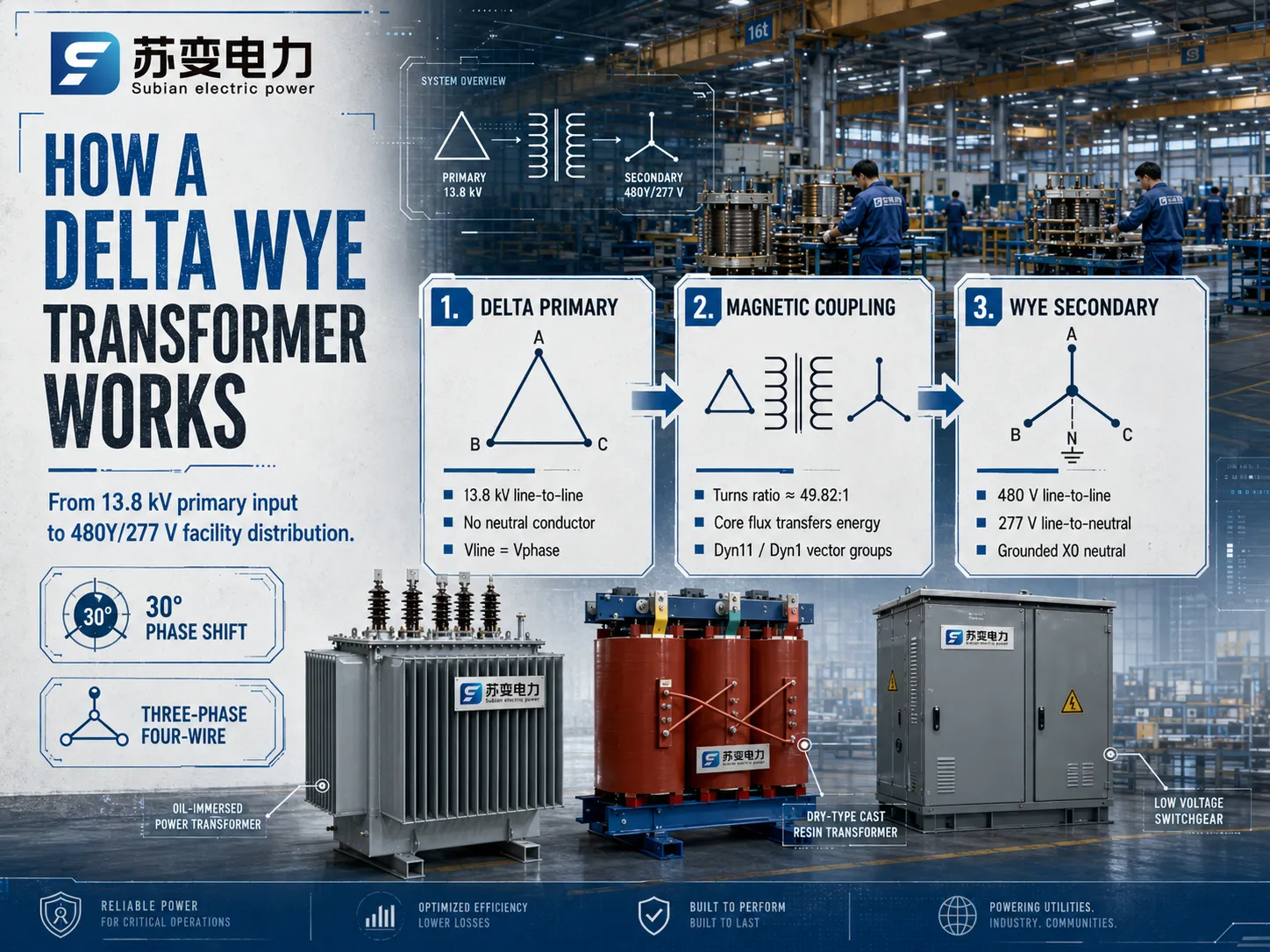
デルタワイ降圧変圧器の電力フローを測定するために、Subian Electricが製造した工業用変圧器を取り上げます。この変圧器は、一次の13,800Vフィーダーの電圧を480Y/277Vに変換します。
一次段階の手順:一次システムでは、13.8 kVの電力会社が三相導体を送電し、中性導体はありません。したがって、中性なしでライン間接続されており、13,800Vに定格されています。.
電磁結合:今、位相電圧に従った巻数比の計算を行う必要があります。二次巻線は277V(480V / √3)の出力を提供します。したがって、変圧器の実際の物理的巻数比は13,800V : 277Vであり、巻数比は約49.82:1です。.
最後に、二次生成:277Vの出力を持つ三つのコイルがワイ構成で接続されると、二つのアクティブ位相が480Vの電圧を生成します。.
ベクトルグループ、角度変位、および位相シフト
変圧器がデルタからワイ構成に切り替えられると、電圧ベクトルに幾何学的なシフトが生じます。多変数電気工学で発生する角度位相シフトは、IEC 60076およびIEEEの仕様に従って時計の表記システムで表されます。.
Dyn11ベクトルグループ
国際的に指定されたさまざまなベクトルグループの中で、Dyn11ベクトルグループが最も広く使用されています。.
D:一次高電圧巻線はデルタ構成で接続されています。.
y:二次低電圧巻線はワイ構成で接続されています。.
n:中性線は外部に引き出され、簡単に接続できるようになっています。.
11:低電圧のライン対中性ベクトルは、高電圧のライン対ラインベクトルを30度の角度でリードします(これは、1時間が30度に相当する時計の11時に対応します)。.
Dyn1ベクトルグループ
対照的に、北アメリカのいくつかの地域グリッドの設置では、Dyn1ベクトルグループが使用されています。ここでの方法は、低電圧ベクトルが高電圧ベクトルに対して30度の角度(1時に相当)だけ遅れることです。両方の変圧器タイプは、電力変換と高調波減衰の点で同一ですが、異なるベクトル構成(例:Dyn11対Dyn1)は互いに並列に接続することができません。異なる位相シフト技術の変圧器が並列に配置されると、角度電圧差の増加により、相対間短絡が発生します。.
デルタ-ワイ構成の主要なエンジニアリング利点
電力システム設計者は デルタ-ワイ変圧器 いくつかの重要な電気性能理由から、代替配置(ワイ-ワイ、デルタ-デルタ、またはワイ-デルタなど)よりも選択します。.
| 変圧器構成 | 中性線の利用可能性 | 第三高調波の挙動 | 不平衡負荷耐性 | 一般的な用途 |
|---|---|---|---|---|
| デルタ – ワイ (Δ – Y) | はい (二次X0) | プライマリデルタループに閉じ込められています | 優れた (中性線は不平衡を処理します) | 工業用配電、商業施設、パッドマウント変電所 |
| ワイ – ワイ (Y – Y) | はい (両側) | 第三のデルタが存在しない限り、中性線が浮遊する可能性があります | 安定化中性点なしの貧弱さ | 高電圧送電インターチェンジ |
| Δ – Δ(デルタ – デルタ) | いいえ(接地バンクが必要) | 両方のデルタループに閉じ込められた | 中程度(1相が故障した場合、オープンデルタで運転可能) | 重工業用モーター負荷、孤立したデルタプラント |
| Y – Δ(ワイ – デルタ) | はい(一次のみ) | 二次デルタループに閉じ込められた | 中程度 | 発電機昇圧トランス(GSU) |
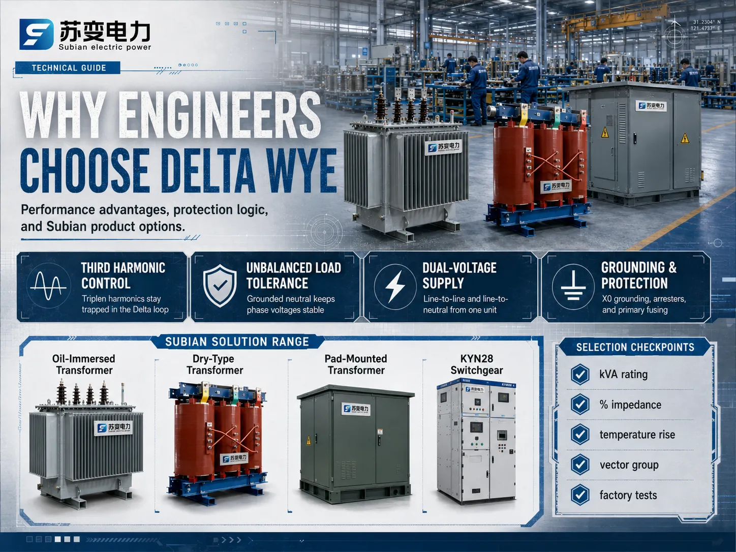
第三高調波電圧の排除
可変周波数ドライブ(VFD)、整流器、コンピュータ電源、LED照明などの非線形負荷は、主に3次高調波(60 Hzシステムで180 Hz、50 Hzシステムで150 Hz)に富んだ電流を引き出します。第三高調波電流はゼロシーケンス成分であり、すべての三相電気の間で完全に位相が一致しています。.
において デルタ-ワイ変圧器, 、二次側で生成されたゼロシーケンス高調波電流は一次巻線に反映されます。一次巻線が閉じたデルタ回路を形成するため、これらの位相が一致した第三高調波電流は三角形のループ内で無害に循環し、一次送電線に逃げることはできません。この効果的な 第三高調波抑制 は、上流の通信干渉を防ぎ、システム全体の電圧歪みを減少させ、上流の電力設備を深刻な過熱から保護します。.
強力な不均衡負荷処理
商業施設や住宅施設では、単相負荷が三相全体に絶対的な数学的対称性で分配されることはまれです。二次側のワイ側で不均衡な状態が発生すると、重要な戻り電流が中性線(X0)を通って流れます。二次中性が物理的に接地されているため、この 不均衡負荷処理 機能により、相対中性電圧が安定したままで、接地されていないワイ-ワイ変圧器によく見られる「中性点のドリフト」や「浮遊中性」として知られる相電圧の歪みを引き起こすことはありません。.
同時二重電圧供給
二次ワイ接続は、単一ユニットから2つの異なる利用電圧レベルを提供します:
- 相対相電圧: チラー、ポンプ、工作機械、製造プロセスラインなどの大きな三相誘導負荷に電力を供給します。.
- 相対中性電圧: 単相建物負荷、一般的なオフィス用コンセント、ビルオートメーション電子機器、建築照明器具に電力を供給します。.
この二重電圧の柔軟性は、施設のスイッチギアアーキテクチャを大幅に簡素化し、補助的な降圧変圧器への初期資本支出を削減します。.
コア飽和と突入電流制御
三相ユニットの磁気コア設計は、エネルギー供給中および故障クリアリング中の非対称フラックス条件に対応する必要があります。閉じたデルタループはゼロシーケンスフラックスが深刻なタンク加熱を引き起こすのを防ぐため、構造用鋼製エンクロージャ内の寄生渦電流を最小限に抑え、絶縁油または固体鋳造誘電樹脂の運転寿命を延ばします。.
Subian Electric Transformer Solutions: 厳しいグリッド向けに設計されています
適切な配電機器を選択することは、高品質の生産、複雑な金属加工、徹底した絶縁試験が関与するため重要です。Subian Electricは、都市の公共事業、商業地域、工業地帯、環境に優しい生産所向けのあらゆる種類の電力変換システムの設計と製造に特化しています。.
Subian油浸型配電変圧器
屋外変電所、電力柱設置、工業プラント変電所向けに、 油浸変圧器 Subian Electricのシリーズは、優れた熱放散と絶縁耐久性を提供します:
- コア技術: ステップラップミタージョイントを持つ高品質の冷間圧延粒状(CRGO)シリコン鋼板から製造されており、無負荷損失を大幅に低減し、運転時の音響ノイズレベルを低下させます。.
- 巻線構造: 高導電性の電解銅または高品質の電気アルミニウム導体を使用し、アップグレードされた熱クラス絶縁紙を特徴としています。高電圧コイルは、短絡電磁ストレスに耐えるよう最適化された頑丈なディスクまたは層状設計で配置されています。.
- 冷却媒体: 高絶縁性の鉱物絶縁油(またはリクエストに応じて生分解性の天然エステル液)は、連続フルロード運転条件下で迅速な対流熱抽出と長寿命の絶縁を確保します。.
Subian乾式キャスト樹脂変圧器
高密度商業タワー、地下鉄システム、医療施設、油の可燃性が許容できない安全リスクをもたらす屋内変電所向けに、 乾式変圧器 Subian Electricの範囲は、最適な火災安全性と耐湿性を提供します:
- 真空圧力鋳造: 高電圧巻線は、高真空下で純粋なエポキシ樹脂に封入され、微小な空気の空隙を排除し、部分放電レベルを10 pC未満に保ちます。.
- 環境分類: 国際的な気候(C2)、環境(E2)、および火災挙動(F1)性能基準を満たすように設計されており、湿気の多い、化学的に攻撃的、またはほこりの多い環境でも運用の信頼性を確保します。.
- 低メンテナンス: 液体絶縁体をサンプリング、フィルタリング、または交換する必要がないため、キャスト樹脂ユニットは非常に低いライフサイクル運用コストを提供します。.
Subianパッドマウント型コンパートメントトランス
商業小売センター、教育キャンパス、データセンター、再生可能エネルギー発電サイトにサービスを提供する地下電気配電システム向けに、Subian Electricは改ざん防止機能を備えた パッドマウント型変圧器 パッケージ:
- 統合安全コンパートメント: 中圧ケーブル終端室と低圧端子コンパートメントを分ける改ざん防止ロック付きの重厚な亜鉛メッキ鋼製エンクロージャ。.
- ループまたは放射状フィード: 2位置または4位置の油中負荷開閉スイッチを利用した放射状フィード単一接続またはループフィード配電システムのいずれかに構成されています。.
- 再生可能エネルギー統合: カスタムエンジニアリングされた 再生可能エネルギー昇圧トランス ユーティリティ規模の太陽光発電(PV)インバータステーションおよび風力発電収集グリッド向けに、インバータのAC出力を直接11 kV、22 kV、または33 kVのコレクタネットワークに昇圧します。.
トランスのサイズ選定およびエンジニアリング選定基準
コンビネーショントランスを指定することは デルタ-ワイ変圧器 単純なkVA定格を超えた運用パラメータの評価が必要です。電気技術者は、負荷プロファイル、故障耐性、環境条件を計算して、早期の熱劣化や予期しないトリップを避ける必要があります。.
見かけの電力(kVA)計算
総見かけの電力定格は、連続定常需要と予想されるピーク過負荷条件の両方を考慮する必要があります。三相システムの場合、必要な容量は次のように決定されます:
kVA = (√3 × V_line × I_line) / 1000
可変周波数ドライブやデータセンターサーバーに高濃度で給電するユニットのサイズを決定する際、設計者はデレーティングファクターを含めるか、ハーモニック負荷電流によって導体に発生する渦電流損失を管理するためにKファクター定格トランス(例:K-4、K-13、K-20)を指定する必要があります。.
インピーダンス率(%Z)および短絡計算
トランスの内部漏れインピーダンス(%Z)は、電圧調整と短絡電流制限のバランスを確立します:
- 低インピーダンス(例:3.5%から4.5%): 大きな負荷変動時の電圧調整を改善し、大型モーター起動時の電圧降下を減少させます。ただし、これにより高い見込み故障電流が発生し、下流のスイッチギアおよび回路ブレーカーにはより高い遮断容量(kA定格)が必要になります。.
- 高インピーダンス(例:5.75%から7%): 短絡故障電流レベルを制限し、下流の保護デバイスおよび配線を保護します。トレードオフとして、重いリアクティブ負荷時の電圧降下がわずかに高くなります。.
温度上昇および絶縁クラス
Subian Electricは、複数の熱絶縁クラスにわたってトランスを製造しています。液体充填ユニットでは、標準設計は30°Cの平均環境基準に対して65°Cの平均巻線温度上昇を提供します。キャストレジン乾式システムでは、クラスF(155°C)およびクラスH(180°C)絶縁材料が、100°Cまたは115°Cの温度上昇での連続的な信頼性のある運転を許可し、内蔵の熱過負荷予備を備えています。.
中性接地およびデルタ-ワイ接続におけるシステム保護
二次スター点 (X0) は デルタ-ワイ変圧器 設備の安全性と保護リレーの基準です。この中性端子が大地にどのように接続されているかが、接地故障条件下での全低電圧配電ネットワークの挙動を決定します。.
固定接地と抵抗接地
- 固定接地中性: X0端子は、低インピーダンス導体を使用して設備接地電極システムに直接接続されています。相対接地故障が発生すると、 substantialな故障電流が即座に流れ、過電流保護装置(モールドケースブレーカー、電子トリップユニット、またはヒューズ)が故障回路を迅速に遮断します。これは商業ビルの電気サービスにおける標準的な実践です。.
- 低抵抗接地 (LRG): 中性接地抵抗器 (NGR) が X0 と大地接地の間に挿入され、通常、接地故障電流を 100A から 400A の間に制限します。LRG システムは、接地故障時のアークフラッシュ危険と大型モーターへの機械的損傷を制限するために、製紙工場、精油所、化学プラントなどの重工業環境で広く使用されています。.
- 高抵抗接地 (HRG): NGR は接地故障電流を 5A または 10A に制限し、これは保護装置を即座にトリップさせるには不十分です。これにより、重要な連続プロセスが電力供給を維持し、オペレーターが故障したラインを特定する間、予定外のシャットダウンを排除します。.
主回路の過電流および雷保護
主デルタ巻線には中性導体がないため、主電力供給線での相対接地故障は上流の変電所ブレーカーによって遮断されなければなりません。変圧器自体を保護するために:
- サージアレスタ: 金属酸化物バリスタ (MOV) サージアレスタは、主ブッシング (H1, H2, H3) のすぐ隣に取り付けられ、大気中の雷インパルスやスイッチングサージを安全に大地に逸らします。.
- 主ヒューズ: パッドマウントユニットでは、ベイオネット電流センサーまたはデュアルセンサーのヒューズが、内部変圧器故障および二次端子短絡から保護するために、電流制限バックアップヒューズと組み合わされています。.
工場試験および品質保証基準
出荷前に運用の完全性を保証するために、最新の電力変圧器は国際基準に準拠した厳格な工場受入試験 (FAT) を受けます:
- 巻線抵抗測定: すべての相コイルがバランスの取れた抵抗を持っていることを確認し、導体の完全性としっかりとしたろう付け接続を確認します。.
- 電圧比およびベクトルグループの検証: すべてのタップチェンジャー位置での正確な巻数比を確認し、30度の角度位相のずれ (Dyn11 または Dyn1) を検証します。.
- 無負荷損失および励磁電流: 定格電圧でのコア損失性能を評価し、コアアセンブリの品質とエネルギー効率の遵守を確認します。.
- 負荷損失および短絡インピーダンス: 銅損失 (I²R) を定量化し、内部インピーダンスがエンジニアリング仕様に一致していることを確認します。.
- 絶縁耐圧試験: ターン間、巻線間、および巻線対接地の絶縁バリアの絶縁強度を確認するために、適用された別電源の電力周波数AC電圧試験と誘導過電圧試験が含まれます。.
- 雷インパルス耐圧試験: 高電圧トランジェントをシミュレートし、絶縁システムが厳しいグリッドの乱れに耐えられることを確認します。.
デルタ・ワイ変圧器に関するよくある質問
配電変圧器の一次側が通常デルタであり、ワイではないのはなぜですか?
一次側をデルタに接続することで、高価な第四の中性導体を長距離の送電および配電距離にわたって運ぶ必要がなくなり、銅またはアルミニウムの材料コストを大幅に節約できます。さらに、デルタループは自然にゼロシーケンスの三次高調波電流を捕捉し、上流の電力配電ネットワークを汚染するのを防ぎます。.
デルタ・ワイ変圧器を逆に使用して電圧を昇圧することはできますか?
物理的に、電磁変圧器は双方向デバイスです。しかし、標準の デルタ-ワイ変圧器 を逆にエネルギー供給すること(ワイ巻線に中電圧を適用してデルタ側の電圧を昇圧すること)は技術的な問題を引き起こします。通常の電力フローの方向は最適なコアジオメトリと巻線構成を決定し、逆の電力フローは過剰な突入電流、コア飽和、および受信側での浮遊中性の問題を引き起こします。これには、適切な接地、サイズ設定、および保護リレーがシステムに設計されている必要があります。.
デルタ・ワイ接続に関連する30度の位相シフトの原因は何ですか?
30度の位相シフトは、ライン間電圧をライン対マイナス電圧に接続することによる幾何学的および数学的な結果です。一次デルタ構成では、ライン電圧は位相電圧に等しいです。二次ワイ接続では、ライン電圧は120度離れた2つの位相電圧のベクトル差に基づいて計算されます。その結果、ライン対ラインのベクトルは位相対マイナスベクトルに対して正確に30電気度シフトします。.
Dyn11とYnd11を区別するものは何ですか?
従来のベクトルグループ表記では、最初の大文字は高電圧巻線を示し、2番目の小文字は低電圧巻線を定義するために使用されます。したがって、Dyn11は中性翼を持つ高電圧デルタ巻線と低電圧ワイ構成を示します。逆に、Ynd11は中性翼を持つ高電圧ワイ構成と低電圧デルタ構成を示し、この構成は通常、大型発電機の昇圧用途に使用されます。.
結論:レジリエントな電力配電ネットワークの構築
この デルタ-ワイ変圧器 商業、産業、公共の電力配電の基盤であり続けています。デルタからワイ変圧器の独自の設計は、一次デルタ巻線の伝送効率と高調波の抑制を組み合わせ、二次ワイ巻線のデュアル電圧運転の柔軟性と接地安定性を提供することで、今日のACシステムが直面する主要な課題を解決します。.
主要な電気原則の重要な理解は、公共ラインでの運用のための油冷式変圧器、建物内に設置するための乾式変圧器、または再生可能エネルギーを収穫するためのカスタムパッドマウント変圧器など、さまざまな変圧器タイプの使用を可能にします。Subian Electricは、現代の電気システムの要件を満たすために準備された効率的な電力変圧器の幅広いラインを提供しています。.