


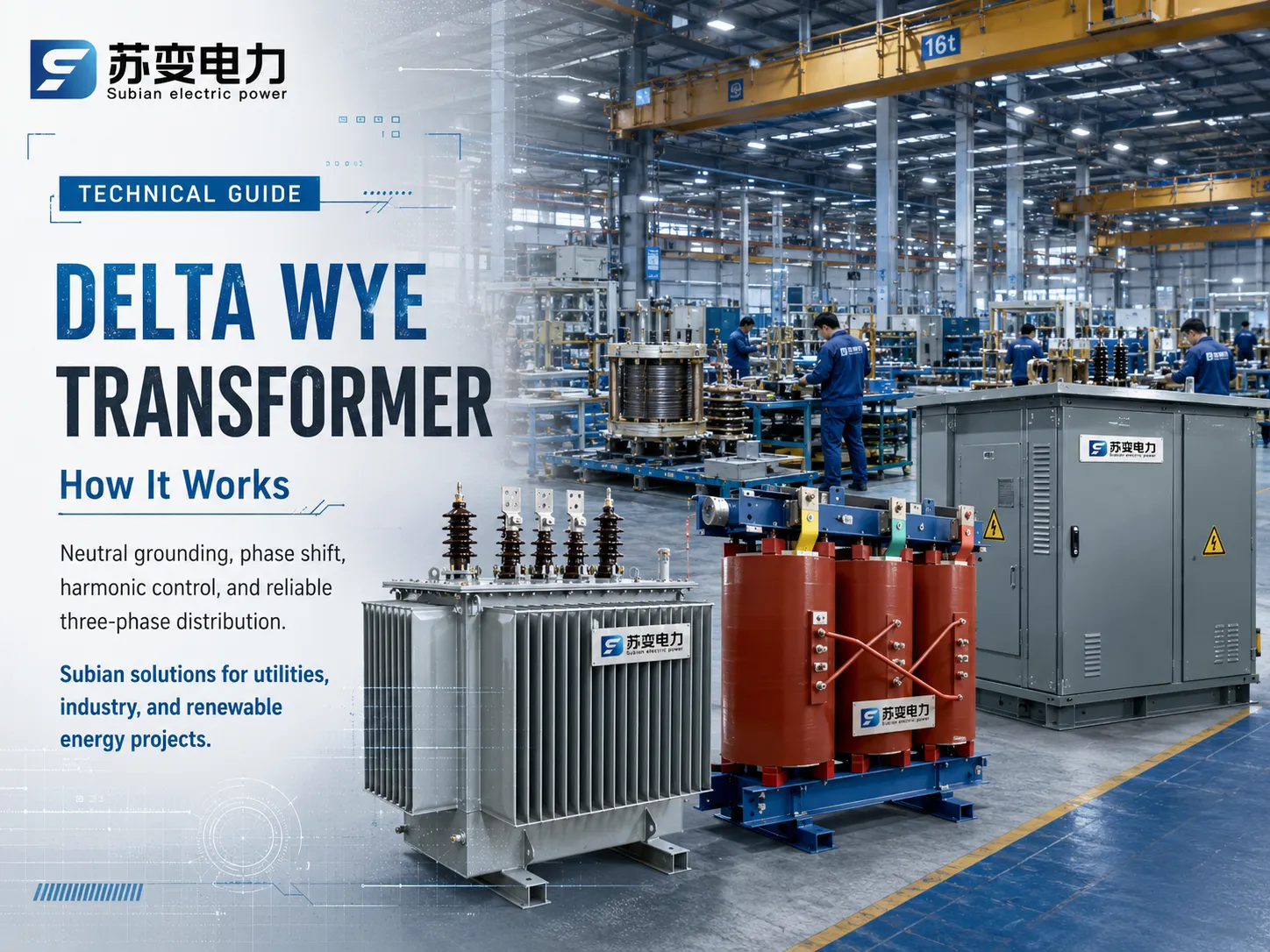
The Delta Wye transformer is one of the widely used three-phase electrical systems in the modern industry and commerce. Electrical engineers utilize the Delta Wye system, to convert medium-voltage distribution utility systems into low-voltage distribution system and vice-versa, and thus it is so important to have knowledge about its electromagnetic processes, vector relationships, and load dynamics in order to pick the right equipment for successful completion of the project. At Subian Electric, specialized distribution devices including high-efficiency oil-immersed transformers systems and reliable dry-type transformers and pad-mounted substations, follow various international norms like IEEE C57, ANSI, IEC 60076. This article opens the fundamentals of the three-phase transformer in Delta-Wye connections explaining its importance for electrical engineering projects across different countries.
Basic Definitions: Learning to Differentiate Between Delta and Wye Connection Types
To understand how a Delta-Wye Transformer works, one has to start with the two fundamental connection types in polyphase AC systems, namely Delta (Δ, mesh) connection and Wye (Y, star) connection.
Delta (Δ) Topology
In Delta topology, three single-phase coils are connected in series such that they form a closed triangular loop. The phase terminals are then led to the three nodes of connection. Since a closed geometric figure is formed:
– The line-to-line voltage is equal to that of phase coil voltage: V_line = V_phase.
– The current in the line is equal to the phase coil current times √3 for a balanced case: I_line = √3 * I_phase.
– The phase current lags behind or leads the line current by electrical angle of 30° depending upon the phase sequence.
– If Delta is used as a simple three-wired circuit, there is no real neutral point meaning that either three-phase loads can’t be started simply using Delta winding with no grounding device.
Wye (Y) Topology
In Wye or star configuration, the beginning of each phase coil is connected to each other at a common node known as the neutral point. The other ends are then connected to the three lines or phases. In doing this, the relationships between the voltages and currents are established.
– The line current is equal to the phase current: I_line = I_phase given that the currents in each line are the same across.
– The line-to-line voltage is equal to √3 times the line to neutral voltage: V_line = √3 * V_phase (for example, 480V line to line voltage means 277V line to neutral voltage or 400V line to line voltage means 230V line to neutral voltage).
– The line-to-line voltage may lead the line-to-neutral voltage by 30°.
– The neutral point may either ground the Wye or may act as a wire establishing a reliable three-phase four-wire system able to provide both single-phase and three-phase loads.
How a Delta Wye Transformer Works: Core Electromagnetic Principles
The three-phase transformer works on the principle of Faraday’s electromagnetic induction law and Ampere’s circuital law. Whenever the three-phase medium voltage supply is connected to the primary Delta terminals (H1, H2, H3), alternating current flows through the primary windings.
These alternations in the current produce a magnetic field within the core consisting of high-permeability grain-oriented silicon steel or amorphous metal. Since the primary circuits are arranged in Delta configuration spanning across two incoming line conductors, they experience the complete primary supply of the current.
The magnetic field produced in the core of each leg is directly connected to the winding placed on the same leg. As per the turns ratio of transformer (N1/N2), the voltages in the secondary windings will be generated proportional to those in the primary windings. In a Delta Wye transformer, all the secondary windings are connected to the neutral busbar and the voltage in the three secondary windings is the voltage across bushings (X1, X2, and X3).
Step-by-Step Voltage and Current Transformation
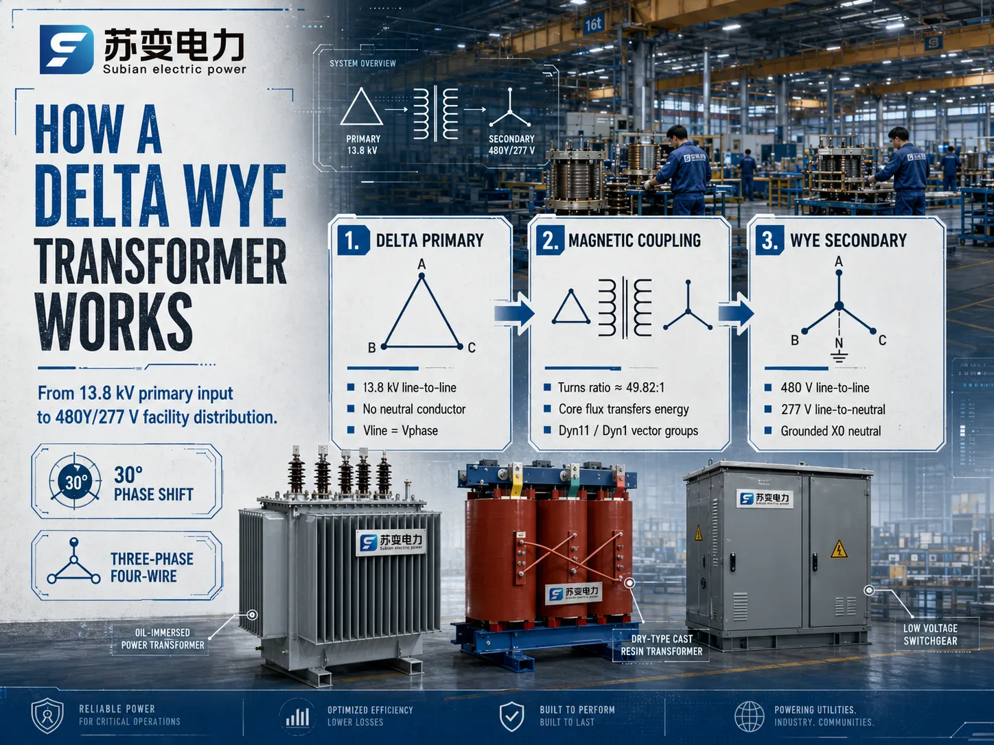
To measure the power flow of a Delta Wye down transformer, we will therefore take one industrial transformer made by Subian Electric, which transforms the voltage of a primary 13,800V feeder into 480Y/277V used by a facility:
Steps for the primary stage: In a primary system, a 13.8 kV utility transmits three-phase conductors and does not have any neutral conductor. So, it has been connected line-to-line without any neutral, which means it has been rated for 13,800V.
Electromagnetic Coupling: Now, the calculation of turns ratio according to the phase voltage needs to be done now. A secondary winding will give an output of 277V (480V / √3). So, the actual physical turns ratio of the transformer should be 13,800V : 277V, which means the turns ratio is about 49.82:1.
Finally, Secondary Creation: When three coils with an output of 277V are connected in Wye formation, two active phases will yield a voltage of 480V.
Vector Groups, Angular Displacement, and Phase Shift
When a transformer is switched from Delta to Wye configuration, there is a geometrical shift in the voltage vectors. The angular phase shift which occurs in multivariable electrical engineering is represented in the clock notation system as per the specifications of the IEC 60076 and IEEE.
The Dyn11 Vector Group
Among the different internationally-specified vector groups, the Dyn11 vector group is the most used.
D: The primary high-voltage winding is connected in a delta configuration.
y: The secondary low-voltage winding is connected in a wye configuration.
n: The neutral wire is brought outside to permit an easy attachment.
11: The low-voltage line-to-neutral vector leads the high-voltage line-to-line vector at an angle of 30 degrees (which corresponds to 11 o’clock on a clock where one hour equals 30 degrees).
The Dyn1 Vector Group
By contrast, installations in some regional grids of North America use the Dyn1 vector group. The method here is that the low-voltage vector lags behind the high-voltage vector by an angle of 30 degrees (which corresponds to 1 o’clock). Although both transformer types are identical in terms of both power transformation and harmonic attenuation, but different vector configurations (e.g. Dyn11 vs. Dyn1) cannot parallel each other. When transformers of different phase-shifting techniques are placed in parallel, significant phase-to-phase short circuit is produced due to the increase in angular voltage difference.
Key Engineering Advantages of the Delta Wye Configuration
Power system designers choose the Delta Wye transformer over alternative arrangements (such as Wye-Wye, Delta-Delta, or Wye-Delta) for several critical electrical performance reasons.
| Transformer Configuration | Neutral Availability | Third Harmonic Behavior | Unbalanced Load Tolerance | Common Applications |
|---|---|---|---|---|
| Delta – Wye (Δ – Y) | Yes (Secondary X0) | Trapped in primary Delta loop | Excellent (Neutral handles unbalance) | Industrial distribution, commercial facilities, pad-mounted substations |
| Wye – Wye (Y – Y) | Yes (Both sides) | Can cause neutral floating unless tertiary delta exists | Poor without stabilized neutral | High-voltage transmission interties |
| Delta – Delta (Δ – Δ) | No (Requires grounding bank) | Trapped in both Delta loops | Moderate (Can run in open-delta if one phase fails) | Heavy industrial motor loads, isolated delta plants |
| Wye – Delta (Y – Δ) | Yes (Primary only) | Trapped in secondary Delta loop | Moderate | Generator step-up transformers (GSU) |
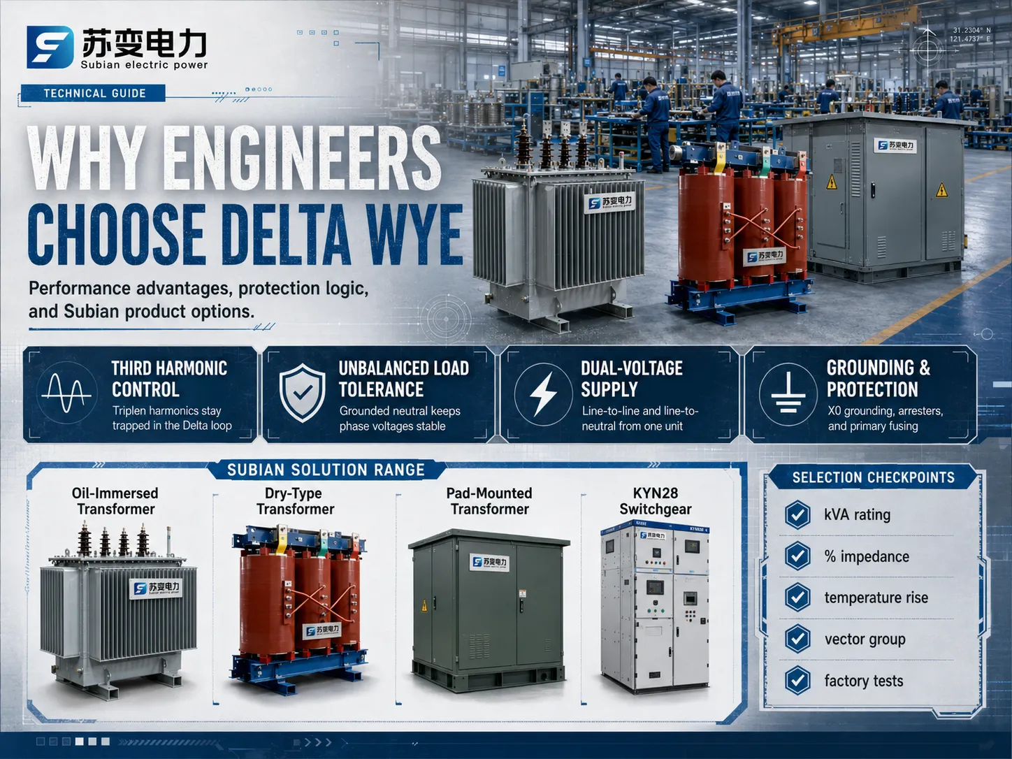
1. Elimination of Third Harmonic Voltages
Non-linear loads such as variable frequency drives (VFDs), rectifiers, computer power supplies, and LED lighting draw currents rich in triplen harmonics, predominantly the 3rd harmonic (180 Hz in a 60 Hz system, 150 Hz in a 50 Hz system). Third harmonic currents are zero-sequence components, meaning they are perfectly in phase with each other across all three electrical phases.
In a Delta Wye transformer, any zero-sequence harmonic currents generated on the secondary side reflect into the primary winding. Because the primary winding forms a closed Delta circuit, these in-phase third harmonic currents circulate harmlessly inside the triangular loop and cannot escape onto the primary transmission line. This effective third harmonic suppression prevents upstream telecommunication interference, reduces system-wide voltage distortion, and protects upstream utility equipment from severe overheating.
2. Robust Unbalanced Load Handling
In commercial and residential facilities, single-phase loads are rarely distributed with absolute mathematical symmetry across the three phases. When an unbalanced condition occurs on the secondary Wye side, significant return current flows through the neutral wire (X0). Because the secondary neutral is physically grounded, this unbalanced load handling capability ensures that phase-to-neutral voltages remain stable without causing the phase voltage distortion known as “neutral point drift” or “floating neutral,” which frequently plagues ungrounded Wye-Wye transformers.
3. Simultaneous Dual-Voltage Supply
The secondary Wye connection delivers two distinct utilization voltage levels from a single unit:
- Line-to-Line Voltage: Powers large three-phase inductive loads such as chillers, pumps, machine tools, and manufacturing process lines.
- Line-to-Neutral Voltage: Powers single-phase building loads, general office receptacles, building automation electronics, and architectural lighting fixtures.
This dual-voltage flexibility drastically simplifies facility switchgear architecture and reduces initial capital expenditure on supplementary step-down transformers.
4. Core Saturation and Inrush Control
The magnetic core design of a three-phase unit must handle asymmetric flux conditions during energization and fault clearing. Because the closed Delta loop prevents zero-sequence flux from creating severe tank heating, it minimizes parasitic eddy currents in the structural steel enclosure, extending the operating lifespan of the insulating oil or solid cast dielectric resin.
Subian Electric Transformer Solutions: Engineered for Demanding Grids
Choosing the right distribution equipment is important because of the high-quality production, complicated metal processing, and thorough dielectric testings involved. Subian Electric has specialized in creating and producing all sorts of power conversion systems for city utilities, trading areas, industrial zones, and environmentally-friendly producing stations.
Subian Oil-Immersed Distribution Transformers
For outdoor substations, utility pole installations, and industrial plant substations, the oil-immersed transformer series from Subian Electric provides superior thermal dissipation and dielectric endurance:
- Core Technology: Fabricated from high-grade, cold-rolled grain-oriented (CRGO) silicon steel sheets with step-lap mitered joints, significantly lowering no-load losses and reducing operational acoustic noise levels.
- Winding Construction: High-conductivity electrolytic copper or high-grade electrical aluminum conductors featuring upgraded thermal class insulation papers. High-voltage coils are arranged in robust disc or layer designs optimized to withstand short-circuit electromagnetic stresses.
- Cooling Media: High-dielectric mineral insulating oil (or biodegradable natural ester fluid upon request) ensures rapid convective heat extraction and long insulation life under continuous full-load operating conditions.
Subian Dry-Type Cast Resin Transformers
In high-density commercial towers, underground rail systems, medical facilities, and indoor substations where oil flammability presents an unacceptable safety hazard, the dry-type transformer range from Subian Electric delivers optimal fire safety and moisture resistance:
- Vacuum Pressure Casting: High-voltage windings are encapsulated in pure epoxy resin under high vacuum, eliminating microscopic air voids and keeping partial discharge levels below 10 pC.
- Environmental Classification: Engineered to satisfy international climatic (C2), environmental (E2), and fire behavior (F1) performance standards, ensuring operational reliability even in humid, chemically aggressive, or dusty environments.
- Low Maintenance: Without liquid dielectric fluids to sample, filter, or replace, cast resin units offer exceptionally low lifecycle operational costs.
Subian Pad-Mounted Compartmental Transformers
For underground electrical distribution systems serving commercial retail centers, educational campuses, data centers, and renewable energy generation sites, Subian Electric produces tamper-resistant pad-mounted transformer packages:
- Integrated Safety Compartments: Heavy-gauge galvanized steel enclosures with tamper-proof locked compartments dividing the medium-voltage cable termination chamber from the low-voltage terminal compartment.
- Loop or Radial Feed: Configured for either radial-feed single connections or loop-feed distribution systems utilizing two-position or four-position under-oil load-break switches.
- Renewable Energy Integration: Custom-engineered as a renewable energy step-up transformer for utility-scale solar photovoltaic (PV) inverter stations and wind power collection grids, stepping inverter AC outputs directly up to 11 kV, 22 kV, or 33 kV collector networks.
Transformer Sizing and Engineering Selection Criteria
Specifying a Delta Wye transformer requires evaluating operating parameters beyond simple kVA rating. Electrical engineers must calculate load profiles, fault withstand capability, and environmental conditions to avoid premature thermal aging or unexpected tripping.
1. Apparent Power (kVA) Calculation
The total apparent power rating must accommodate the continuous steady-state demand as well as expected peak overload conditions. For a three-phase system, the required capacity is determined by:
kVA = (√3 × V_line × I_line) / 1000
When sizing units that feed high concentrations of variable frequency drives or data center servers, designers should include a derating factor or specify a K-factor rated transformer (e.g., K-4, K-13, K-20) to manage eddy current losses in the conductors caused by harmonic load currents.
2. Percent Impedance (%Z) and Short-Circuit Calculations
The internal leakage impedance (%Z) of the transformer establishes the balance between voltage regulation and short-circuit current limitation:
- Low Impedance (e.g., 3.5% to 4.5%): Improves voltage regulation under heavy load swings and reduces voltage drop during large motor starts. However, it results in higher prospective fault currents, requiring downstream switchgear and circuit breakers with higher interrupting capacities (kA ratings).
- High Impedance (e.g., 5.75% to 7%): Restricts short-circuit fault current levels, protecting downstream protective devices and cabling. The trade-off is slightly higher voltage drop under heavy reactive loading.
3. Temperature Rise and Insulation Class
Subian Electric builds transformers across multiple thermal insulation classes. In liquid-filled units, standard designs provide a 65°C average winding temperature rise over a 30°C average ambient baseline. In cast resin dry-type systems, Class F (155°C) and Class H (180°C) insulation materials permit continuous reliable operation at 100°C or 115°C temperature rises with built-in thermal overload reserves.
Neutral Grounding and System Protection in Delta Wye Installations
The secondary star point (X0) of a Delta Wye transformer is the anchor for facility safety and protective relaying. How this neutral terminal is referenced to earth dictates the behavior of the entire low-voltage distribution network during ground fault conditions.
Solid Grounding vs. Resistance Grounding
- Solidly Grounded Neutral: The X0 terminal is bonded directly to the facility grounding electrode system with a low-impedance conductor. Under a phase-to-ground fault, substantial fault current flows immediately, enabling overcurrent protective devices (molded case circuit breakers, electronic trip units, or fuses) to clear the faulted circuit rapidly. This is standard practice in commercial building electrical services.
- Low-Resistance Grounding (LRG): A neutral grounding resistor (NGR) is inserted between X0 and earth ground, typically limiting ground-fault currents to between 100A and 400A. LRG systems are prevalent in heavy industrial environments (such as paper mills, refineries, and chemical plants) to limit arc flash hazards and mechanical damage to large motors during ground faults.
- High-Resistance Grounding (HRG): The NGR restricts ground fault current to 5A or 10A, which is insufficient to trip protective devices immediately. This allows critical continuous processes to remain energized while operators locate the faulted line, eliminating unscheduled shutdowns.
Primary Overcurrent and Lightning Protection
Because the primary Delta winding lacks a neutral conductor, phase-to-ground faults on the primary utility feeder must be cleared by upstream substation breakers. To safeguard the transformer itself:
- Surge Arresters: Metal-oxide varistor (MOV) surge arresters must be mounted immediately adjacent to the primary bushings (H1, H2, H3) to divert atmospheric lightning impulses and switching surges safely to ground.
- Primary Fusing: In pad-mounted units, bay-o-net current-sensing or dual-sensing fuses combined with current-limiting backup fuses protect against internal transformer faults and secondary terminal short circuits.
Factory Testing and Quality Assurance Standards
To guarantee operational integrity before dispatch, modern power transformers undergo rigorous factory acceptance testing (FAT) complying with international standards:
- Winding Resistance Measurement: Verifies that all phase coils have balanced resistances, confirming conductor integrity and solid brazed connections.
- Voltage Ratio and Vector Group Verification: Confirms precise turns ratios on all tap changer positions and validates the 30-degree angular phase displacement (Dyn11 or Dyn1).
- No-Load Loss and Exciting Current: Evaluates core loss performance at rated voltage to verify core assembly quality and energy efficiency compliance.
- Load Loss and Short-Circuit Impedance: Quantifies copper losses (I²R) and verifies that internal impedance matches engineering specifications.
- Dielectric Withstand Testing: Includes applied separate-source power frequency AC voltage tests and induced overvoltage testing to confirm the dielectric strength of the turn-to-turn, winding-to-winding, and winding-to-ground insulation barriers.
- Lightning Impulse Withstand Test: Simulates high-voltage transients to ensure the insulation system withstands severe grid disturbances.
Frequently Asked Questions About Delta Wye Transformers
Why is the primary side of a distribution transformer usually Delta instead of Wye?
Connecting the primary in Delta eliminates the need to run an expensive fourth neutral conductor over long utility transmission and distribution distances, saving significant copper or aluminum material costs. Furthermore, the Delta loop naturally traps zero-sequence third harmonic currents, preventing them from corrupting the upstream utility distribution network.
Can a Delta Wye transformer be used in reverse to step up voltage?
Physically, electromagnetic transformers are bidirectional devices. However, energizing a standard Delta Wye transformer in reverse (applying medium voltage to the Wye winding to step up voltage on the Delta side) creates technical complications. Normal power flow direction dictates the optimum core geometry and winding configuration; reverse power flow causing excessive inrush current, core saturation and floating neutral problems on the receiving end unless adequate grounding, sizing and protective relaying are designed into the system.
What is responsible for the 30-degree phase shift associated with Delta Wye connections?
The 30-degree phase shift is a geometrical and mathematical result of connecting line-to-line voltages to line-to-minus voltages. In the primary Delta configuration, line voltage is equal to phase voltage. In the secondary Wye connection, line voltage is calculated based on the vector difference between 2 phase voltages that are separated by 120 degrees. As a result, the line-to-line vector is shifted exactly by 30 electrical degrees with respect to the phase to minus vector.
What distinguishes Dyn11 from Ynd11?
In the conventional vector group notation, the first capital letter indicates a high-voltage winding while the second small letter is used to define the low-voltage winding. Thus, Dyn11 indicates a high-voltage Delta winding with low-voltage Wye configuration with a neutral wing. Conversely, Ynd11 indicates a high-voltage Wye configuration with a neutral wing and a low-voltage Delta configuration, thus this configuration is usually used for large generator step-up applications.
Conclusion: Building Resilient Power Distribution Networks
The Delta Wye transformer remains the bedrock of commercial, industrial, and utility power distribution worldwide. The unique design of the Delta to Wye transformer solves major challenges facing today’s AC systems by combining transmission efficiency and suppression of harmonics of the primary Delta winding with the flexibility of dual voltage operation and grounded stability of the secondary Wye winding.
The important understanding of key electrical principles allows the usage of various transformer types, be it oil-type transformer for operation on the utilities line, dry-type transformer for installation inside a building, or custom pad-mounted transformer for harvesting renewable power. Subian Electric offers a wide range of efficient power transformers ready to meet the requirements of every modern electrical system.