


ステップアップトランスとステップダウントランスは、電磁誘導を介して同じ物理原理を利用してAC電圧を変更しますが、電気ネットワークの両側に位置し、電圧と電流に関して実行する機能が逆になります。同じメカニズムで動作しているにもかかわらず、構造の品質に関して異なるわけではありません。むしろ、両者の違いは、1つのトランスがもう1つよりも多くの巻数を持っているという事実にあります。これにより、トランスが設置場所に応じて電圧と電流にどのように影響を与えるかが決まり、機械の価格にも大きな影響を与えます。この記事では、トランスの種類のすべての特徴を説明し、購入者に実用的なアドバイスを提供します。.
答えは次のとおりです:ステップアップトランスは、二次側に巻かれたコイルが一次側よりも多く設計されており、入力よりも出力で高い電圧を生成します。同じ原理が適用され、高い電圧で電力を伝送することによって抵抗損失を減少させます。ステップダウントランスは、二次側の巻数が一次側よりも少ないため、出力電流の比例的な増加とともに低い電圧を生成します。両方のタイプのトランスは、同じ方程式Vs/Vp = Ns/Npに基づいていますが、電流は逆比例します。トランスは、逆に設置された場合、どちらのタイプとしても機能しますが、ステップダウントランスは、巻き方、絶縁、特定の電力フローのモードに関連する冷却システムのため、ステップアップトランスに変換された場合に常に定格出力を生成するわけではありません。.
�¤のタイプとは何か
両方の装置は静的機械の一種です。それぞれが磁気コア上に2つ以上の巻線を持っています。一次巻線は交流を流し、磁気コア内に変化するフラックスを生成します。このフラックスは、二次巻線と呼ばれる他の巻線に誘導電圧を生成します。2巻線トランスでは、2つの巻線は電気的に接続されていません。両方の装置には、可動部品はありません。.
ステップアップトランスとステップダウントランスを区別する唯一の設計上の特徴は、巻数比です。二次巻線が一次巻線よりも多くの巻数を持つ場合、二次巻線の誘導電圧は高くなり、トランスはステップアップトランスになります。二次巻線の巻数が一次巻線よりも少ない場合、それは電圧が低く、トランスはステップダウントランスになります。トランスの他のすべての特徴は、前述の巻数比がどのように実現されるかに関連しています。.
これはかなり広範な誤解の正確なポイントであると言うことが重要です。ポイントは、昇圧トランスが降圧トランスよりも強力でないということです。昇圧トランスの定格出力が500 kVAであるという事実は、それが同じ出力の降圧トランスよりも強力な機械であることを意味しません。.
昇圧トランスの動作
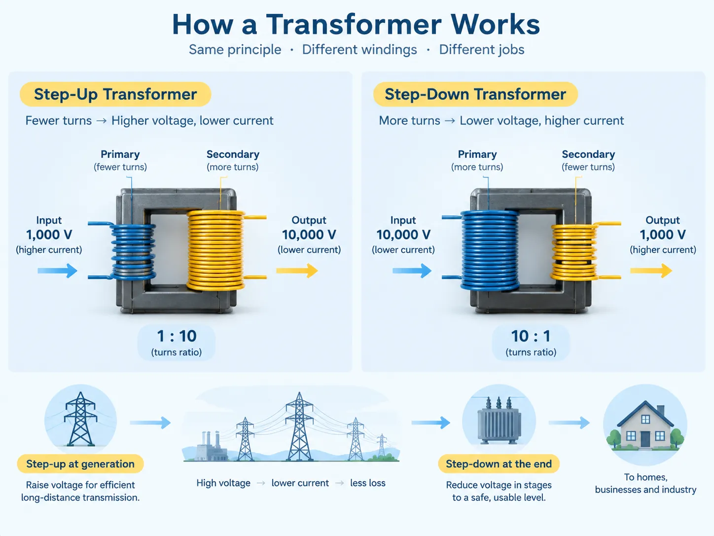
昇圧トランスの使用は、電力供給が巻線の少ない方に供給され、利用は巻線の多い方から取られることを意味します。もし一次側の巻数が100で、二次側の巻数が1,000であれば、巻数比は1:10となり、トランスの二次側の電圧は一次側の電圧の10倍になるべきですが、損失や調整に関するいくつかの例外があります。.
主なポイントは電流への影響です。トランスは電力を生成するのではなく、ただ転送するだけなので、電圧が上昇すれば電流は減少します。例えば、昇圧トランスが1,000ボルトの供給から10,000ボルトの電圧を通過させると、電流は一次側の初期電流の十分の一に減少します。この関係はトランスの欠点ではなく、一般的な物理法則に従って高い電圧は小さい電流を意味するという点で、トランスの主な目的です。.
したがって、発電側からすべての電力システムに昇圧トランスの一部が見られることがあります。発電機は、絶縁によって制限された電圧、より正確には大きな発電機では11 kVから25 kVの範囲で電力を生成します。その後、昇圧トランスがこの電圧を必要な送電値に引き上げ、275 kVから400 kV以上になることがあります。これらの機械がどのように構築され、ネットワーク内でどこに位置するかの基本は 配電トランスの基本構造と役割, に示されており、同じ原則が小規模で共有されています。.
降圧トランスの動作原理
降圧トランスでは、巻線の順序が逆になり、供給が巻数の多い方に適用され、負荷は巻数の少ない方から取られます。10:1の比率を持つ降圧トランスの例では、10,000 Vで供給されると1,000 Vを供給し、出力電流も同じ10倍の係数で増加します。.
ステップダウントランスの存在理由の一つは、発電地点から使用地点までの伝送に効率的な電圧に大きな違いがあるためです。長距離伝送には275 kVの伝送電圧が使用されることがありますが、そのような高電圧に実際に接続できる建物、機器、装置はありません。電圧は実用的な使用に適したレベルまで徐々に減少させる必要があります。この目的のために、伝送からサブ伝送、次に一次配電、最後に設置に適したレベルまで多くの段階で減少させることができます。供給が確立される前に、いくつかのステップダウン変換を行う必要があるかもしれません。.
ステップダウントランスの動作に関する特定の特徴について言及する必要があります。まず第一に、電圧が減少すると、低電圧巻線の電流は高電圧巻線よりもはるかに高い値を持つため、低電圧巻線は高電圧巻線よりも重く作られなければなりません。これが、トランスの低電圧巻線を認識しやすい理由です。第二に、出力における電圧の安定性はより重要であると感じられます。なぜなら、設置は特定の電圧範囲にのみ耐えられるからです。名前プレートと仕様パラメータの完全なセット、およびそれぞれがサービス中の動作にどのように影響するかは、以下で説明されています。 トランス仕様の解釈.
サイドバイサイド比較
| パラメータ | ステップアップトランス | ステップダウントランス |
|---|---|---|
| ターン比 | 二次巻数 > 一次巻数 | 二次巻数 < 一次巻数 |
| 電圧 | 入力よりも出力が高い | 入力よりも出力が低い |
| 電流 | 入力に対して逆比例で出力が低い | 入力に対して逆比例で出力が高い |
| 電力 | 損失を除いて変わらない | 損失を除いて変わらない |
| 主な機能 | 伝送損失を減少させるために電圧を上げる | 使用可能なレベルまで電圧を下げる |
| 一般的な場所 | 発電時、および配電のために電圧を上げる必要がある地点 | サブステーション、建物の供給地点、および使用のすべての地点 |
| 一般的な電圧ペア | 11-25 kVから132-400 kV | 132-400 kVから11-33 kV、次に400 Vまたは230 V |
| より重い巻線 | 二次(高電圧)、ただし絶縁が優先される | 二次(低電圧)、電流が高いため |
| 絶縁の強調 | 重い — 高電圧巻線が設計とクリアランスを駆動する | 高側は中程度、低側は最小限 |
| 同等のMVAでの一般的な相対コスト | 絶縁とクリアランス要件のために高い | 同じ見かけの電力定格の場合は低い |
| 効率 | 非常に高い、通常は大きな定格で98-99% | 非常に高い、通常はサイズに応じて97-99% |
| 原則として可逆 | はい、設計限界内で逆給電される場合 | はい、設計限界内で逆給電される場合 |
�¤の行は、顧客を驚かせるため、いくつかの説明が必要です。両方のタイプの変圧器が同じ電力を扱う場合、なぜ昇圧変圧器はその対抗品よりも高価なのでしょうか?その答えは絶縁システムにあります。高電圧の二次側を持つように設計された変圧器は、巻線の絶縁、ブッシング、接地へのクリアランス、インパルス耐圧を扱わなければなりません。これらの要件は電圧に依存し、電力には依存しません。したがって、50 MVA 11 kV/132 kVの昇圧変圧器は通常、大きく、より優れた絶縁を持ち、50 MVA 132 kV/11 kVの降圧変圧器よりも高価です。両方のユニットは仕様上似ているように見えるかもしれませんが。.
How They Differ Physically
The external appearance of a step-up and a step-down transformer with the same specifications can be confusing due to the similar construction. And yet, there are certain features the transformer has that help determine its type.
- Bushing height and size. Thanks to the high-voltage winding, the bushing design is different. With that in mind, it is easy to tell which side is used for high-voltage transmission. In a step-up transformer that would be the secondary winding, while in a step-down transformer, it would be the primary one.
- Winding conductor cross-section. If there is an opportunity to make a visual check, it is possible to say whether the winding belongs to a step-up transformer or a step-down transformer by the thickness of the conductors.
- Cooling arrangement. In case of the larger units of both speculations, there are radiators, fans or pumps to provide oil for cooling, but it is not a distinguishing feature for both types, as the cooling class is given in the rating plate.
- Taps used in the winding. The tap changer is usually installed on the high-voltage winding, as this construction allows fine tuning of the transformer for the same number of turns in the winding.
In all cases, the nameplate proves to be of great help in deciding which type of the transformer is available.
Where Each Is Used
The two types occupy opposite ends of a chain that every unit of electricity passes through.
| ステージ | 変圧器の役割 | 一般的な定格 |
|---|---|---|
| 発電 | Generator step-up transformer raises machine voltage to transmission level | 50-1,000 MVA |
| トランスミッション | Step-up and step-down at interconnection points between voltage levels | 100-1,000 MVA |
| サブ送電 | Step-down from transmission to sub-transmission voltage | 20-200 MVA |
| 主配電 | Step-down from sub-transmission to distribution voltage | 5-50 MVA |
| 配電変電所 | Step-down to utilisation voltage for an area or a large site | 0.5-5 MVA |
| Point of use | Step-down to the installation’s operating voltage, or local step-up for a specific machine | 0.025-2.5 MVA |
| Specialist local use | Step-up for a specific process or test requirement, such as electrostatic precipitators or test benches | Varies widely |
It can be inferred from the last two rows that both forms of transformations can occur in the same factory facility. A factory can receive electricity by the step-down transformer and then it may have a small step-up transformer to use it for a specific process such as electrostatic precipitators or dielectric test sets, or special equipment which requires higher voltage than what is supplied through the distribution. The direction of the transformation depends on the needs and not on the place where it is located; thus, the sizing problem has to be solved based on the requirements in terms of voltage and power.Getting that arithmetic right is a prerequisite for specifying anything correctly, and the method is set out in the approach to transformer sizing and load calculation.
タイプと構成
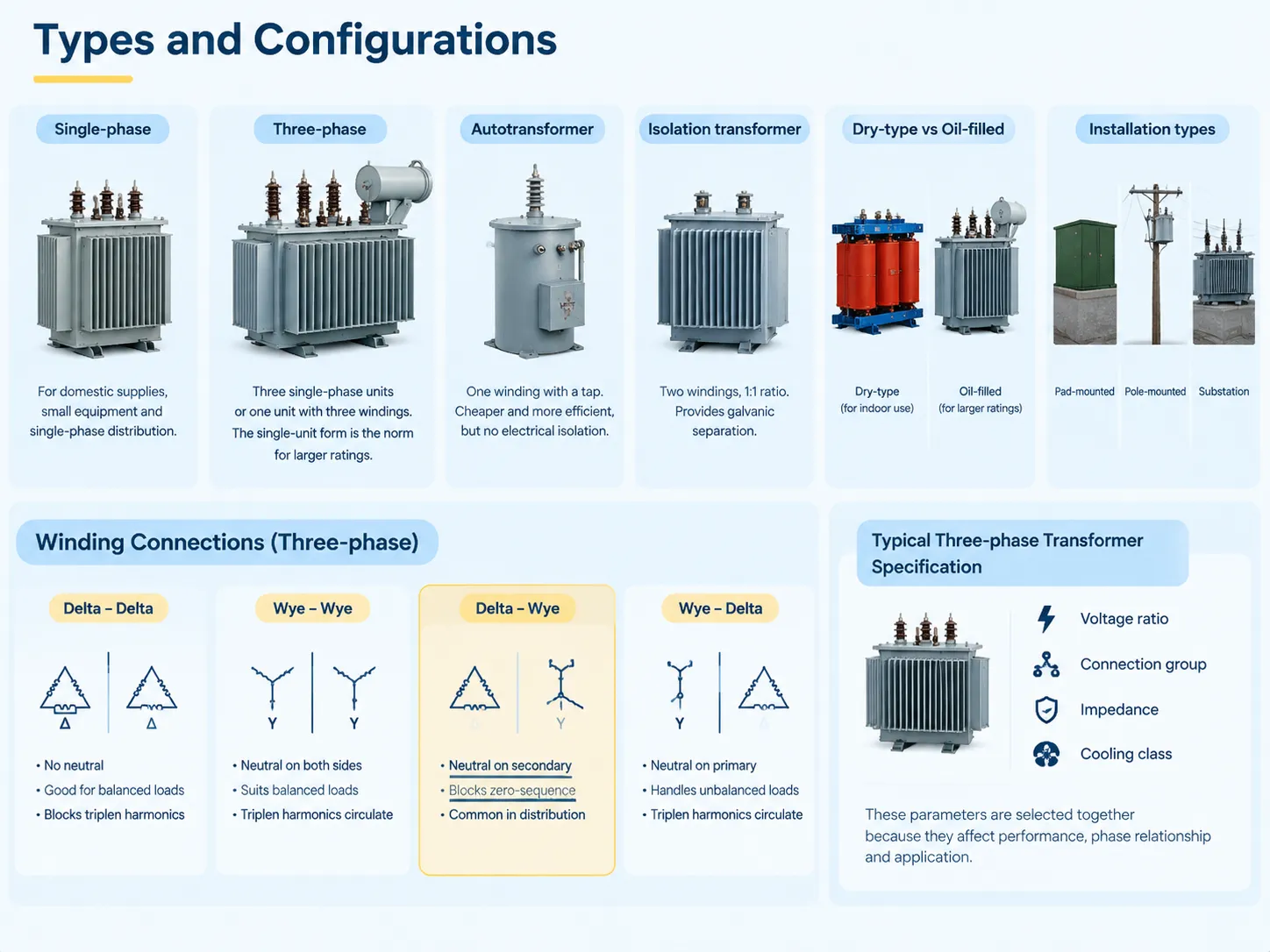
The construction family of the transformers does not tally with the direction of transformation, since both step-up and step-down transformers belong to the same family of construction.
- Single-phase. Made up of two windings on one core, widely used for home and small equipment supply and distribution, commonly used for smaller capacities.
- Three-phase. Consisting of either three single-phase transformers, or one three-phase transformer which has three windings on the same core. The second design favours the majority of transformer constructions due to its inherent capacity for powering transformers of very large rating and in providing installation with other parameters related to transformer operation.
- Autotransformer. A transformer with a single winding on tap that has electromagnetic coupling of circuits. It is the most cost-effective solution when compared to a two-winding transformer for similar purpose.
- Isolation transformer. A transformer with two windings and 1:1 turns ratio designed for specific needs of galvanic isolation.
- Dry and oil-filled types. Their distinction lies in the location where they are used: the dry type can work in closed spaces and the oil-filled ones are mostly employed for transformers that are big enough and have higher capacities, since oil cooling is more effective than air one.
- Pad-mounted and pole-mounted transformers, or transformers in substations. They are rather concerned with the installation methods than with the principle of transformers’ work.
For work done over three phases, the way the windings are connected — whether through delta or wye — significantly affects how phases of primary and secondary work together, along with whether a neutral is there and how unbalanced loads and triplen harmonics are handled by the transformer. An example would be a delta-wye connection that offers a neutral at the secondary and blocks the zero-sequence current from passing through it.The practical implications of each combination are significant enough to drive the specification, and a representative example of how a three-phase unit is presented for procurement is the 三相変圧器の範囲, where voltage ratio, connection group, impedance and cooling class appear together because they must be selected together.
Prices and Cost Drivers
Transformer pricing is conditioned by similar factors in the opposite direction, where direction of the installed unit does not matter as much as voltage class or voltage rating.
| Cost driver | Effect on price | 理由 |
|---|---|---|
| Power rating (kVA or MVA) | Dominant driver; price rises faster than rating | More core steel, more copper, more oil, larger tank |
| 電圧クラス | Major driver, especially on the high-voltage side | Insulation, clearances and bushing costs scale steeply with voltage |
| Cooling class (ONAN, ONAF, OFAF) | 中程度 | Radiators, fans and pumps add cost but raise usable rating |
| Impedance specification | 中程度 | Low impedance costs more in material; affects fault level and regulation |
| Tap changer (off-circuit or on-load) | Significant for on-load | On-load tap changers are complex mechanisms with their own controls |
| 損失仕様 | Significant | Low-loss designs use more active material to reduce operating cost |
| Connection group and neutral arrangement | Minor to moderate | Affects winding configuration and any neutral bushing |
For the buyer, the key factors are that when comparing price offers from multiple suppliers, a product specification should be taken into account, since, after all, cheap price often translates into cheaper voltage class, small cooling margin or higher losses than in a good deal; and that the price of the product is only one part of the total cost, since losses are paid throughout the entire service life of the product. Reconciling capital cost against lifetime energy cost is the central exercise in transformer procurement, and the realistic price bands for each rating and class are set out in the cost structure for electrical transformers.
Can a Step-Down Be Used as a Step-Up?
In theory, it is possible. A transformer is a reversible device and turning the supply towards what is being called its secondary will mean that the voltage on what is being called primary will be higher than expected. On some occasions, this is done on purpose in case of emergency.
However, in reality the following four points define the reason why this is a bad idea unless made as part of a rational engineering choice. They are usually installed on the high-voltage winding which implies that reverse feeding of the transformer will situate them in unsuitable places for voltage adjustment. The insulation and distances were made with the assumption that the high voltage will appear on a certain winding, but back-feeding can expose this voltage to a wiring arrangement not convenient for it. The parameters for cooling and current ratings were set with a certain current distribution through the windings assumed, which will now turn when the power flow gets reversed. The protection and earthing system that would normally be designed for a particular direction of power flow will not be suitable for reversed flow either.
To summarize, reversal is theoretically possible to do, may be appropriate in certain situations, but is better clarified with the manufacturer rather than assumed. If one does require both directions at site, using a transformer properly selected for the job would be a much smarter approach than compromising by using whatever transformer one happens to have.
How to Tell Which You Have
Four tests in an order of reliability.
- Check the rating plate. It states the rated voltage of each winding as identified by terminal markings as well as the rated power, type of connection group, impedance, and the class of cooling. This is the most accurate test and can be carried out within seconds. If it is not possible to identify rating plate because of its illegibility or absence then other tests will become just approximations.
- The next test is to make a comparison of bushings and the clearance. The high-voltage side is identified by the side where bushings are larger and spacing and clearance to the earth are wider.
- Make a check of the size of the conductors whenever it is possible to see it. The heavier conductor belongs to the winding with the higher current and lower voltage.
- Trace the connection. Follow the supply line to find out which winding is the primary one and compare it with the rated voltage of the winding being investigated.
There are two remarks about field identification. If a transformer has a ratio of 1:1, for example, that is the isolation transformer, it does not step-up or step-down voltage and an attempt to identify the transformer by the direction will yield only a wrong result. Moreover, a transformer having many taps can be connected in such a way as to change its nominal ratio. Thus what is shown on the plate may not reflect the actual situation.
よくある質問
What is the difference between step-up transformers and step-down transformers?
The differentiation resides in the number of coils in winding. A step-up transformer has a greater number of coils in the secondary coil because of which the voltage of the output is greater than that of the input as well as the current is less proportionately. The purpose of the step-up transformer is to boost the voltage level to ensure the efficiency of power transmission. Meanwhile, a step-down transformer decreases the number of coils in its secondary coil leading to the decrease of voltage and increase of current in the proportion. The step-down transformer is used to lower the voltage to an appropriate level. Though both transformers operate at the same efficiency level, the following equation is true for both types of transformers Vs/Vp = Ns/Np.
What is the disadvantage of a step-up transformer?
There are three drawbacks that should be taken into account. To begin with, with the same power rating, costs tend to be higher than for step-down transformers as the high-voltage winding uses insulated parts and clearance materials that are connected with voltage parameters rather than power output. Next comes the risk that is connected with the potential failure of insulation systems due to the greater power of possible failures in the case of using high voltage equipment. Thirdly, when one uses a step-up transformer supplying a long cable, it is necessary to address voltage rise at the cable ends due to low voltage load conditions. Despite the fact that step-up transformers are quite reliable under normal conditions, all of the indicated factors affect the process of their specification and protection.
Can a step-down transformer be used as a step-up transformer?
In terms of functionality, the transformer can certainly operate in a reverse mode as there are situations where this is done in emergency situations. However, a device that has been intentionally built for use as a step-down transformer will usually not be able to achieve its full capacity when connected to the line in reverse mode because of numerous factors including but not limited to the design of the transformer in terms of winding construction, number of taps in use, and cooling arrangements. In reverse operation, the taps will usually remain on the primary (high voltage) side which may be regarded as inappropriate for operation. It is always advisable to check the reversibility option with the manufacturer and the devices that are made specifically for this purpose should be installed rather than recompleting the one that was not made for reverse operation.
How to tell if it’s a step-up or step-down transformer?
Examine the rating plate, which provides the rated voltage for each winding and is conclusive. In the absence of the rating plate, compare the bushings; the side with the bigger bushings, greater spacing and larger clearance from earth is said to be the high-voltage side, meaning that it is the side to which the transformer steps up and down from. In instances where the conductors are visible, noting the sizes of the conductors is the second clue; since the larger conductor is used for the winding with the higher voltage and lower current. Then follow the supply line to find out which of the windings is in fact the primary, as transformers with various taps may not always be installed in the configurations that results in the effective ratio being same as in the nameplate specifications.
Which transformer is used in a substation?
In both cases, the substation serves the reciprocal function. In the primary substation, transmission voltage is lowered to the level of distribution voltage. Therefore, all transformers in this type of substation are called step-down transformers. In a generation facility, the substation serves a different purpose since it is raising the voltage produced by the generator to the level of voltage transmission by using a step-up transformer. When it comes to interconnection substations, they might work in both modes, as they may contain both step-up and step-down units depending on the direction in which electricity flows most frequently and switching the flow if the flow does not change at the generation and demand points.
参考文献
- International Electrotechnical Commission — IEC 60076 Power Transformers
- IEEE — Transformer Connections, Voltage Regulation and Loading Guides
- ANSI — ANSI C57 Series Power Transformers, Regulators and Reactors
- NFPA — National Electrical Code, Article 450 Transformers and Transformer Vaults
- U.S. Department of Energy — Transformer Efficiency and Distribution System Losses
結論
Step-up and step-down transformers are different sides of the same coin. The only difference is the number of turns in each transformer. In step-up transformers the secondary winding has more turns than the primary winding; thus, the transformer raises voltage and lowers current. Electricity transmission at high voltage is far more effective than doing so at low voltage — which is why the step-up transformer was invented in the first place. The step-down transformer on the other hand has fewer turns on the secondary winding and lowers voltage while raising current. Basically, there is no such thing as a transformer that could be connected to the transmission line. Both transformers transfer the same amount of power except for losses involved, and they obey the same formula Vs/Vp=Np/Ns. They are built in the same manner — the only thing that differentiates them is their position in the electric power transmission system and that makes step-up and step-down units price different. The step-down unit can be used as a step-up transformer but its efficiency will be the lowest because it is designed to work only in one way.