


전류 변환기(CT)는 직접 측정할 수 없는 대량의 전류/수준을 측정하기 위해 계측/보호 시스템과 함께 사용되는 장치입니다; 400, 1000 및 3000 A의 전류를 5 또는 1 A의 사용 가능한 값으로 변환합니다. 이 변화는 CT 장치가 따라야 할 특정 조건 하에서 발생합니다: 극성이 올바르게 설정되어야 하며, 부하가 정확해야 하고, 전류가 흐르는 동안 2차 배선은 절연 회로에 노출되어서는 안 됩니다. 매뉴얼에는 CT와 계측, 릴레이 및 모니터링 장치의 배선 연결에 대한 사양, 배선을 단계별로 설정하는 방법 및 삼상 모델의 배선 방법이 포함되어 있습니다.
장치에 연결된 기본 전류 또는 도체가 변환기 P1 및 P2를 통과하도록 허용되는 경우, P1 및 P2의 2차 단자에서 기록된 판독값이 잘못될 수 있습니다. 이는 S1이 모든 경우에 P1과 일치하지 않을 수 있기 때문이며, 이로 인해 S1 S2 연결에서 전류의 전압 판독값이 발생할 수 있습니다. 단일 변환기를 사용할 경우, 모든 삼상 연결에 대해 S1 및 S2 연결은 사용되지 않습니다. 단일 CT를 사용할 경우 S1과 S2의 두 개에 대해 항상 직접 연결이 이루어지므로 다른 연결 방법은 필요하지 않습니다. 삼상 배선의 경우, 변환기는 “Y” 또는 스타 연결 방법을 사용하여 연결해야 하며, S1은 세 개의 계측 입력에 연결되고 S2 연결은 위의 두 방법과 관계없이 공통 스타 지점에 연결됩니다.
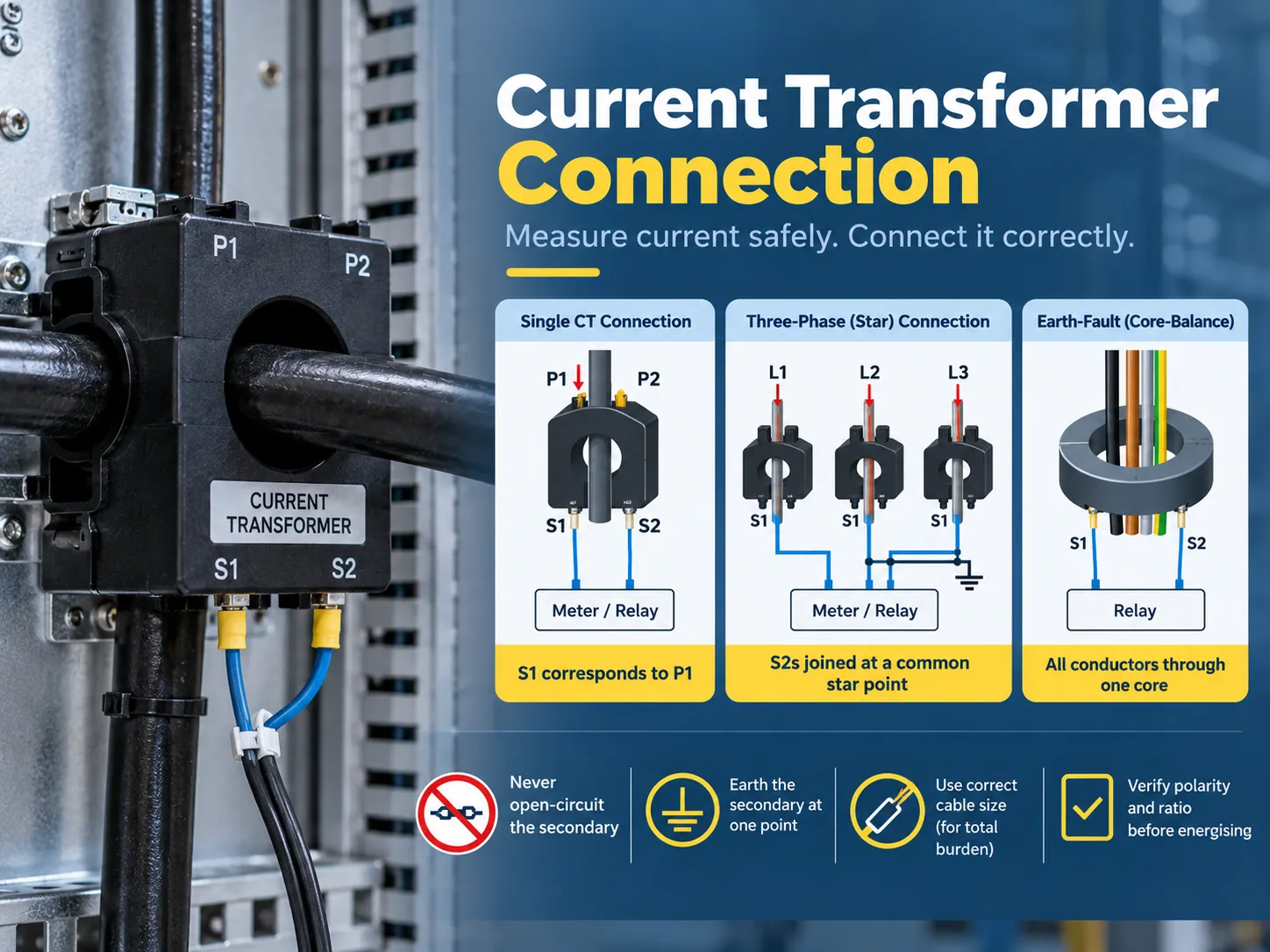
전류 변환기가 하는 일과 연결이 중요한 이유
CT는 기본 전류를 받아 비례하는 2차 전류를 생성하면서 기본 회로로부터 절연을 보장하는 방식으로만 작동할 수 있는 특수 변환기입니다. 400/5 CT는 기본 전류가 400 암페어일 때 2차에서 5 암페어를 생성합니다. 또한, 반부하에서 2.5 암페어를 제공하며, 연결된 미터기나 릴레이는 이 정보를 해석하여 다시 기본으로 전달합니다.
| CT 유형 | 구조 | 일반적인 사용 |
|---|---|---|
| 바-기본(창) CT | 기본은 고정 바 또는 버스바가 창을 통과합니다. | 스위치기어, 패널 계량, 기존 바 주변의 리트로핏 |
| 권선-기본 CT | 기본은 단자(P1/P2)로 연결된 권선입니다. | 저비율 및 특수 비율 응용 프로그램 |
| 분할 코어 CT | 분리 없이 기존 도체 주위에 클램프 | 리트로핏 에너지 모니터링, 서브 미터링 |
| 부싱 CT | 변압기 또는 차단기 부싱에 내장됨 | 변압기 및 스위치기어 보호 |
| 코어-밸런스(제로-시퀀스) CT | 모든 상 도체가 하나의 코어를 통과합니다. | 지락 감지 및 민감한 누설 측정 |
CT가 어떻게 연결되어야 하는지를 보여주는 두 가지 중요한 요소가 있습니다. 보조 전류의 비율은 특정 기본 전류(예: 400/5 또는 1,000/1)에 대해 CT가 제공할 전류의 양을 의미합니다. VA로 표시된 부하는 CT의 성능에 영향을 주지 않고 CT에 부착해야 하는 부하(계량 및 릴레이)의 양을 나타냅니다. 따라서 CT가 올바른 비율에 따라 작동하더라도 부하가 잘못 설정되면 측정값이 정확하지 않을 것입니다.
단자 및 극성: P1, P2, S1, S2
CT 단자는 문자 이해가 이루어지면 배선이 항상 명확해지는 정해진 규칙을 따릅니다:
| 단자 | 의미 | 연결 규칙 |
|---|---|---|
| P1 | 기본, 극성이 표시된 쪽 | 일반적으로 전원(도체의 입력 측)을 향합니다 |
| P2 | 기본, 비표시된 쪽 | 부하를 향합니다 |
| S1 | 보조, P1에 해당 | S1로 표시된 기기 입력에 연결됩니다(또는 “라인”/극성 입력) |
| S2 | 보조, P2에 해당 | S2로 표시된 기기 입력에 연결되거나 삼상 회로의 스타/공통 지점에 연결됩니다 |
극성 규칙은 시운전 실패의 주요 원인입니다. S1은 항상 기기의 S1 입력과 일치해야 하고, P1은 전원과 일치해야 하므로 CT의 방향이나 S1에서 S2로의 연결이 변경되면 측정된 전류가 반전됩니다. 방향 감지 보호 응용 프로그램이 실패할 수 있으며, 수입으로 표시될 수 있는 전력(kW)의 측정값도 반대로 나타날 수 있습니다. 반면 K 및 L과 같은 표시는 일부 제조업체에서 사용될 수 있지만, 원리는 동일합니다(K는 P1과 일치하고 L은 P2와 일치해야 함), 즉 명판이 배선을 지시해야 하며 생활 방식이 아니라는 의미입니다.
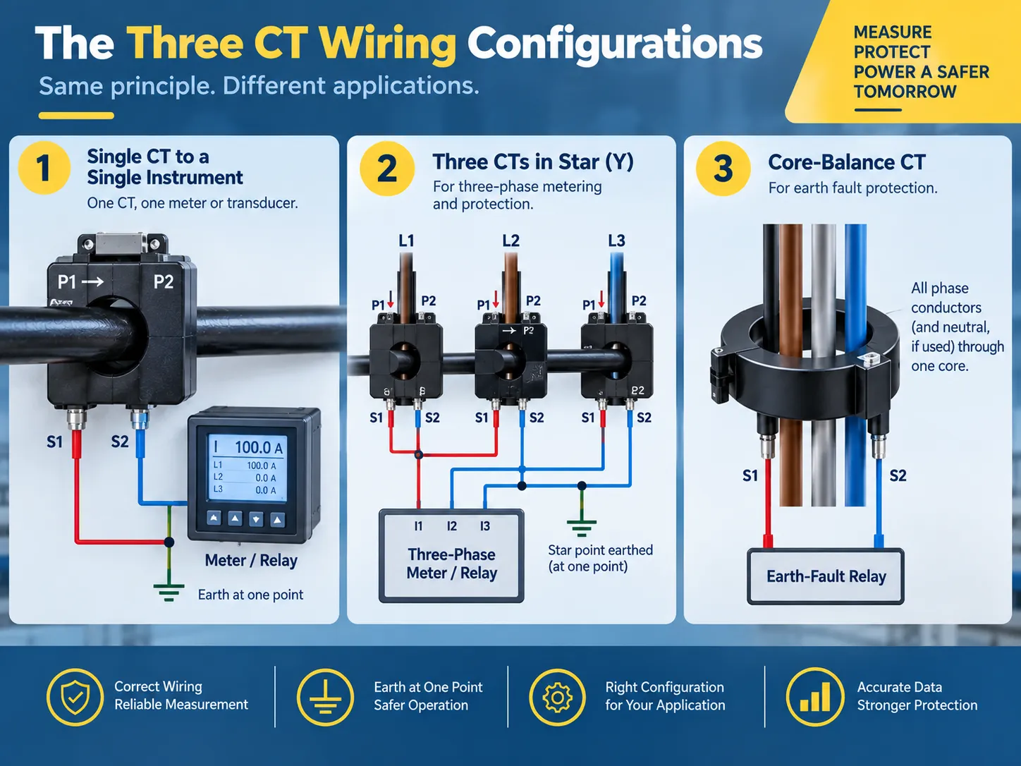
실제로 사용할 세 가지 배선 구성
CT의 거의 모든 설치는 세 가지 유형의 구성으로 나뉩니다:
- 단일 기기와 함께 사용되는 하나의 CT. 하나의 CT가 계량기 또는 센서와 함께 사용됩니다: S1은 기기의 S1에 연결되고, S2는 기기의 S2에 연결되며, 보조 측은 한 지점(일반적으로 기기 패널)에서 접지됩니다. 이는 전용 피더 패널 또는 모터 전류 모니터링을 위한 표준 사용 방법입니다. 삼상, 4선 계량의 경우 동일한 절차가 세 번 반복됩니다.
- 삼상 계량 및 보호를 위한 Y 구성에서 세 개의 CT 사용. 여기서 모든 세 개의 S1 전선은 해당 기기 전류 입력에 연결되고, 모든 세 개의 S2 전선은 단일 스타 지점으로 연결됩니다. 이 스타 지점은 보조가 접지되는 지점입니다. 스타 구성은 삼상 에너지 계량기 및 전력 계량기의 기본 구성으로 사용되며, 이는 위상 전류의 정확한 복사본을 제공하고 전류 불균형을 위한 경로를 제공합니다.
- 코어 밸런스 CT는 지락 감지를 위해 사용됩니다. 이 경우, 모든 세 개의 상 전도체(응용 프로그램에 따라 중성선 포함)가 하나의 CT 코어를 통과합니다. 정상 상태에서는 전류의 벡터 합이 0이 되며, 따라서 CT 2차측은 0을 읽습니다. 지락이 발생하면 중성선 대신 지구를 통해 일부 전류가 돌아오고, 이는 지락 릴레이에 의해 감지되는 잔여 신호를 생성합니다. 이 설정에서는 배선이 덜 복잡합니다(2개의 2차선만 릴레이로 연결됨)만, 특정 물리적 규칙을 준수해야 합니다: 다른 전선은 코어를 통과할 수 없으며, 케이블 차폐 또는 아머는 잔여 전류를 상쇄하는 병렬 경로를 생성할 수 없습니다.
동일한 CT가 계량기와 보호 릴레이 모두에 데이터를 제공해야 하는 경우, 두 부하가 직렬로 배선됩니다(먼저 계량기, 그 다음 릴레이 또는 CT에 여러 개의 2차가 있는 경우 대체 코어를 사용하여) 병렬로 연결되거나 사용되지 않는 코어와 함께 연결되지 않습니다. 잔여 연결 뒤에 있는 보호 철학은 우리의 지락 보호 기본 사항 가이드에서 더 설명됩니다.
CT 연결 다이어그램, 설명
CT 배선 도면은 1차 측에서 시작하여 계측기로 끝나는 방식으로 읽어야 합니다. 다음은 다이어그램으로 제시된 3상 계량 설치의 예입니다:
| 전도체에서 | 에 | 지휘자 |
|---|---|---|
| A상 도체(소스 측) | CT-A P1 | 기본 회로 — CT 배선 아님 |
| CT-A S1 | 계측 전류 입력 IA (S1) | 5-4 mm² 구리, 600 V 정격 |
| CT-A S2 | 스타 지점 | S1과 동일한 크기 |
| CT-B S1 | 계측 전류 입력 IB (S1) | 동일한 크기 |
| CT-B S2 | 스타 지점 | 동일한 크기 |
| CT-C S1 | 계측 전류 입력 IC (S1) | 동일한 크기 |
| CT-C S2 | 스타 지점 | 동일한 크기 |
| 스타 지점 | 접지(한 지점만) | 지역 코드에 따른 접지 도체 |
| 각 S1/S2 쌍 | 단락/테스트 단자 블록 | CT와 계측기 사이에 설치됨 |
프로젝트에 제공된 배선 다이어그램이 있는 경우, 이를 기본 소스 문서로 사용해야 합니다. 그러나 설치를 완료하기 전에 다음 세 가지 규칙을 사용하여 확인해야 합니다: S1과 S1 쌍 사용, 단일 접지 지점 사용, 회로 내 단락 메커니즘 존재. 이 세 가지 측면에서의 불일치는 부적절한 시운전으로 이어질 수 있으며 안전하지 않은 조건을 초래할 수 있습니다.
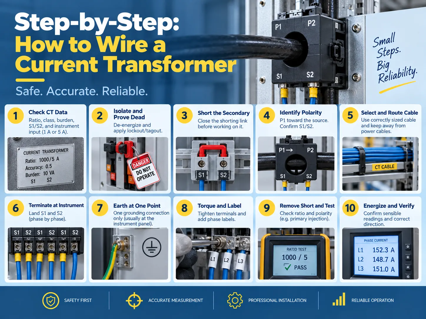
단계별: 전류 변환기 배선 방법
- 첫 번째 단계는 CT 데이터를 확인하고 계측기 요구 사항을 점검하는 것입니다. 비율, 정확도 등급, 부하(VA) 및 극성 표기를 확인하기 위해 명판을 확인하십시오. 계측기의 입력 정격(1 A 또는 5 A)이 CT 2차와 일치하는지 확인해야 합니다. 5 A CT가 1 A 입력에 연결되면 계측기는 다섯 배의 오차로 잘못 판독되며 입력이 포화될 수 있습니다.
- 장치는 격리되어야 하며, 이후 고장 상태를 확인해야 합니다. 기본 회로는 전원이 차단되어야 하며, 적절한 잠금/태그 아웃 조치가 적용되어야 합니다. “기본 회로가 격리되었더라도, 다른 소스에서 전원이 공급되는 활성 CT 2차가 있을 수 있다”는 점을 기억하는 것이 중요하며, 따라서 모든 CT 회로는 다른 방법으로 입증될 때까지 활성으로 간주해야 합니다.
- 다음 단계는 2차 회로를 단락하는 것입니다. 테스트 단자 블록의 단락 링크를 닫거나 S1과 S2를 연결하기 위해 적절한 단락 장치를 사용할 수 있습니다. 이 절차는 CT 고장의 위험을 제거합니다.
- 다음 단계는 P1 및 P2의 기본 포인트와 S2 및 S1의 2차 포인트를 찾는 것을 포함하는 극성을 찾는 것입니다. 기본 방향(여기서 P1이 소스를 향하는 위치)과 물리적 배열이 도면과 일치하는지 확인하는 것이 필수적입니다.
- 적절한 2차 케이블을 선택해야 합니다. 적절한 크기의 구리 도체를 사용해야 하며, 이는 부하 및 전선 길이에 대해 (표준 2.5 mm², 600볼트) 전력 도체가 외피 내에서 흐르지 않도록 하면서 모든 세 가지 상을 달성하는 것을 목표로 합니다.
- 종단은 기기에서 S1이 기기의 S1(극성) 입력에 있고 S2가 두 번째 입력에 있도록 해야 합니다.
- 접지는 일반적으로 기기 또는 릴레이 패널 중 하나의 지점에서만 이루어져야 합니다.
- 제조업체에 따라 토크 설정을 확인하고 비율 레이블을 포함하여 상에 레이블을 부착해야 합니다.
- 테스트가 시작되기 전에 단락 링크를 제거해야 하며, 비율과 극성을 확인해야 합니다.
- 전원 회로를 켜서 회로가 기기에서 올바르게 읽히도록 하며, 모든 세 가지 상이 현재 읽기에서 기록되고 있는지 확인합니다.
부하 및 케이블 크기: 대부분의 설치자가 건너뛰는 계산
전류 변압기(CT)는 정격 부하를 초과하면 정확하지 않습니다. 부하 총계에는 2차에 연결된 모든 장치와 2차 배선의 저항이 포함됩니다:
- 기기 부하: 이는 계기 또는 릴레이 제조업체가 지정한 VA 부하(또는 저항)입니다. 기기 유형에 따라 다를 수 있지만, 일반적으로 현대 전자 기기의 경우 전류 입력당 0.2-1 VA 범위에 있으며, 구형 전자기 릴레이의 경우 더 높은 부하가 있습니다.
- 배선 부하: 배선 저항은 다음과 같이 계산됩니다: 2 x 편도 길이 x 미터당 저항(예: 2.5 mm² 구리 배선의 저항은 약 7.4 ohm/km), 2차 전류의 제곱을 곱합니다. 전선 길이에 따라, 배선 부하로 인해 기기 부하가 초과되는 경우가 드물지 않습니다.
- 연결 부하: 단자 및 테스트 블록 간의 저항은 일반적으로 작지만, 배선 총계가 CT 부하에 가까운 경우 이 값을 포함해야 합니다.
CT의 총 부담이 정격을 초과하면 정확한 측정을 제공할 수 없으며, 고장 전류 동안 포화될 수 있습니다. 이때 보호가 가장 필요합니다. 가능한 해결책으로는 짧은 케이블 경로, 더 큰 도체 사용, 낮은 부담의 기기 사용 또는 더 높은 VA 정격의 CT 구매가 있습니다.
정확도 클래스 자체 — 계량용 0.5 및 1, 보호용 5P 및 10P — 는 우리의 변압기 정확도 클래스 가이드.
특정 설치에 대한 비율 선택 논리는 부하 전류 및 고장 수준에서 최종 명판 선택까지 우리의 전류 변압기 비율 선택 기사에 요약되어 있습니다.
테스트 및 검증
CT가 부하를 수용하기 전에 올바르게 설치되었는지 확인하기 위해 세 가지 테스트가 사용됩니다:
| 테스트 | 그것이 증명하는 것 | 방법 |
|---|---|---|
| 비율 테스트 | CT는 알려진 1차 전류에 대해 예상되는 2차 전류를 생성합니다. | Primary injection at a fraction of rated current, or a secondary-voltage method for large CTs |
| Polarity test | S1 truly corresponds to P1 and the instrument reads forward power correctly | DC pulse or primary injection with a polarity-sensitive instrument |
| Insulation and continuity | No shorted or open secondary conductors, and adequate insulation to earth | Insulation resistance and continuity checks before energization |
Post-energization verification is equally important because you should compare the readings of the CT with a reading from a clamp meter on the primary side, verify that the readings are consistent across all three phases, and confirm that the earth-fault circuits register zero residuals on a healthy feeder.Where the CT is part of a protection scheme, that coordination — and the grounding references it depends on — is the subject of our 변압기 접지 기초 가이드에서 더 설명됩니다.
Safety rules, and the mistakes that damage equipment
The secondaries of current transformers only flow small amounts of current at low voltages—until something goes wrong. The following are mandatory guidelines for dealing with current transformer circuits:
- Never open the current transformer circuit secondaries while the primary circuit is energized. The current transformer will attempt to generate very high voltages (hundreds or thousands of volts) across the secondary terminals when it is open, leading to an extreme overvoltage situation, core saturation, overheating, and potentially explosion and fire.
- Ground the current transformer secondary only at one point. Connecting the ground at two points will cause unnecessary current to circulate through the ground contributing to an incorrect measurement and potentially causing an unnecessary trip of protection equipment.
- Avoid installing a switch or fuse in the current transformer circuit that is not a shorting type of test block. Standard circuits may fail open which creates the same condition as an open circuit.
- Do not leave spare current transformer cores open. Short the unused coils and note them on the drawing, or future technicians may be incorrectly leading service personnel to assume that they are open circuits.
- Be sure to observe proper polarity at each connection. The S1-to-S1 and P1-to-source connections are not arbitrary conventions that may be changed later.
- Keep current transformer wires away from power and variable frequency drive (VFD) cables, and do not pass the current transformer around just a single part of the conductor in a core balance scheme.
Two other practical points to remember are that a current transformer must be hooked up with the instrument input rating matching the transformer’s secondary rating (either 1A or 5A) and that the primary conductor must pass through the window in one direction only. Passing a bar or cable back through the core backwards will reverse the effective polarity of the current transformer.For meters that must be removed for calibration, the test block should be the type that automatically shorts the CT when the instrument is unplugged; the wiring practices around metering and instrument transformers are also covered in our current transformer installation guide.
자주 묻는 질문
What are the disadvantages of using a current transformer?
There are several drawbacks; having an open-circuit secondary is dangerous since it creates the possibility of serious injury; calculation of the connected load must be done correctly, or else inaccurate readings will be produced; incorrect polarity can result not only in inaccurate readings but also in malfunctioning protection devices; there is a small phase shift introduced by the CT that results in a slight inaccuracy in measurements; added expense and panel space; proper sizing is necessary, otherwise, the CT will saturate during a fault condition. Although modern electronic meters do reduce some of the problems associated with these drawbacks, all of them cannot be eliminated.
How are current transformers wired?
To connect the primary conductor through the CT there is P1 (the source side) and P2 (the load side) or the line is passed through the bar / window. The secondary side will be S1 and S2 with S1 corresponding to P1. The S1 and S2 will lead to either a meter, relay, or transducer directly for a single CT or in a star configuration for three-phase metering (three S1s to the meter and three S2s coupled to one grounded star point, etc.). There is a shorting/test terminal block mounted at the juncture of the CT and the instrument.
Does it matter which wire goes where on a transformer?
For any transformer it does; however, CTs have unique requirements. This is due to the leads having a specific polarity (i.e., S1 correlating to P1). By reversing these two leads, it causes current to flow in the opposite direction creating inaccurate power readings along with the possibility of malfunctioning protection devices. This is applicable in both transformers with respect to the primary and secondary leads.
How do you connect an electrical transformer?
In the case of an instrument transformer such as a CT: verify the ratio and the burden, isolate the transformer and prove it to be dead, short out the secondary side, identify which lead corresponds to P1 and which lead corresponds to S1; connect the correctly sized secondary cable such that S1 and S2 lead to the instrument’s respective inputs, ground the secondary at one point, label and torque the connection, remove the ground; and finally inject a known standard into the system to verify polarity and ratio. The process for connecting a power transformer differs from this procedure but still requires the individual to verify ratings, polarity, grounding, and testing before energizing load.
참고 문헌
- IEEE — C57.13, Standard Requirements for Instrument Transformers
- IEC — 61869 Series, Instrument Transformers
- NFPA — National Electrical Code (Instrument Transformer Circuits)
- NETA — Acceptance Testing Specifications for Electrical Power Equipment
결론
The installation of the current transformer carries a lot of weight although it may seem like an unimportant task. The function of the current transformer is to reduce the amount of primary current flowing through the wire to a safe reading for the meter or relay. Therefore, you can see how important this task is in the long run. For the primary wire (P1) you will have to run wire to the source while the secondary wire (S1) will run from the current transformer to the meter or relay. If you are wiring three-phase meters, the circuits must be wired in a star pattern and grounded at a single point to earth. Use a core-balance CT for residual currents; make sure you size the secondary wire appropriately according to the burden load. Always use a test block to short out the circuit before energizing it and never break the circuit as long as current is flowing through the primary side. Make sure that you check the readings first using primary injection and then record the ratio on the sheet for future reference.