


변압기는 수명 주기 동안 여러 시점에서 일련의 테스트를 거치며, 이러한 각 테스트는 서로 다른 범주에 속하고, 통과 기준은 테스트마다 다르게 측정됩니다. 예를 들어, 멀티미터를 사용하여 간단한 12 V 제어 변압기를 테스트하는 것은 결과가 두 경우 모두 동일하다는 사실을 제외하고는 1 MVA 배전 변압기를 시운전하는 것과 전혀 유사하지 않습니다. 이 기사는 각 테스트가 무엇을 달성하는지, 수행하는 데 필요한 사항, 결과를 해석하는 방법, 그리고 안전 인식이 있는 모든 사람이 준수해야 할 규칙을 설명합니다.
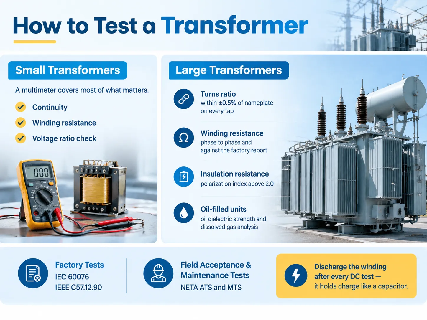
간단히 답변: 멀티미터는 소형 변압기에 대해 연속성, 권선 저항 및 전압 비율 검사를 수행할 수 있으며, 이는 대부분의 기능을 포함합니다. 그러나 대형 변압기의 경우 표준 배터리를 사용해야 하며, 이는 각 탭에 대해 명판에서 ±0.5% 이내의 변환 비율을 확인하고, 상간의 권선 저항과 공장 값을 확인하며, 편극 지수가 2.0보다 큰 절연 저항을 확인해야 합니다. 오일 충전 변압기는 IEC 60076 및 IEEE C57.12.90에 명시된 공장 기준에 따라 절연 강도 및 용해 가스 분석을 테스트해야 합니다.
변압기 테스트의 네 가지 종류
테스트가 실행되는 시점에 따라 분류하는 것은 왜 이렇게 많은 테스트가 있는지를 이해하는 가장 빠른 방법입니다.
| 카테고리 | 목적 | 언제 | 규제 참조 |
|---|---|---|---|
| 정기(공장) 테스트 | 제작된 모든 장치에 대한 품질 관리 | 제조 중 모든 장치 | IEC 60076-1, IEEE C57.12.00 |
| 유형(설계) 테스트 | 설계가 사양을 충족하는지 증명 | 설계당 한 번, 또는 프로토타입에서 | IEC 60076-3, IEEE C57.12.90 |
| 특별 테스트 | 고객 지정 추가 증거 | 요청 시 | 계약 의존 |
| 수용/시운전 테스트 | 장치가 손상 없이 도착했으며 올바르게 설치되었는지 확인 | 첫 번째 전원 공급 전 | NETA ATS, IEEE C57 |
| 유지보수 테스트 | 서비스 수명 동안 상태 추적 | 주기적이거나 고장 또는 사건 후 | NETA MTS, IEEE 62 |
수용 테스트와 유지보수 테스트의 차이는 보이는 것보다 더 중요합니다. NETA 수용 테스트 사양(ATS)은 장비 사용 전에 적용되며 동일한 장치의 기초를 설정합니다. 유지보수 테스트 사양(MTS)은 사용이 시작된 후 동일한 장비에 적용되며, 유사하지만 동일한 프로세스는 아닙니다. 테스트 자체는 유사하지만 결과와 목적은 다릅니다.
시운전의 경우, 타임라인을 계획할 때 알아야 할 또 다른 중요한 구분이 있습니다: 완료가 다음 단계에 결정적인 시운전 체크리스트가 있으며, 각 단계의 완료가 다음 단계에 중요합니다. 올바른 순서로 단계를 진행하고, 진행하면서 기준 값을 기록하는 것이 이 변압기 시운전 체크리스트.
도구 및 각 도구가 알려주는 것
| 도구 | 테스트 | 감지하는 내용 |
|---|---|---|
| 디지털 멀티미터 | 연속성, 전압 비율, 공급 검사 | 열린 권선, 총 비율 오류, 공급 누락 |
| 저저항 옴미터 / 마이크로 옴미터 | 권선 저항 | 느슨한 연결, 끊어진 가닥, 나쁜 탭 접촉 |
| 변압기 변환 비율(TTR) 세트 | 변환 비율 및 극성 | 잘못된 탭, 단락된 권선, 개방된 권선, 잘못된 연결 |
| 절연 저항 측정기 (메거) | IR, PI, DAR | 습기, 절연 열화, 오염 |
| 절연 전력 계수 / 탄젠트 델타 설정 | 소산 계수, 정전 용량 | 절연 노화; GST/UST 구성에서 부싱 상태 |
| 오일 테스트 키트 (BDV 셀, 습기) | 오일 유전 강도, 수분 함량 | 오일 오염 및 습기 침투 (액체 충전만 해당) |
| DGA 샘플링 장치 | 용해 가스 분석 | 아킹, 열적 결함, 부분 방전, 셀룰로오스 노화 |
| SFRA 분석기 | 스윕 주파수 응답 분석 | 운송 후 또는 통과 결함으로 인한 권선 변형 |
| 클램프 미터 및 열화상 카메라 | 부하 전류 및 열 조사 | 불균형 부하, 뜨거운 연결, 냉각 문제 |
두 가지 사항에 대해 경고할 가치가 있습니다. 변압기가 전자 보호 장치, 낙뢰 서지 보호기 또는 제어 패널에 연결된 상태에서 메거를 사용하면 이들이 망가집니다. 항상 먼저 격리하고 분리하는 것을 확인하세요! 또 다른 사항은 열 검사입니다 — 변압기가 비전압 상태일 경우 아무 의미가 없습니다.
테스트 전: 시각적, 기계적 및 안전
적절하게 수행된 시각적 검사 결과로 절반의 결함이 발견된다는 점이 주목됩니다.
- 플레이트 및 문서. 테스트 프로그램에 따라 전압, 정격 용량, 벡터 그룹, 임피던스, 온도 분류 및 탭 설정을 확인하세요. 잘못된 명판에 대해 장치를 테스트하면 하루가 망가질 수 있습니다.
- 물리적 상태. 운송 손상, 오일 누출, 부싱 손상, 느슨한 연결, 터미널 박스 내 습기, 코어 브래킷의 이동, 고장 난 압력 게이지.
- 오일이 채워진 장비의 오일 수준 및 상태. 흐리거나 변색된 오일은 그 자체로 발견입니다.
- 접지 및 본딩. 탱크의 접지, 중성 접지, 코어의 접지 및 관련 본딩 점퍼의 연속성.
- 격리 및 잠금. 전원 공급 장치를 격리하고, 잠금 장치 및 태그를 적용하며, 작업 지점에서 전원이 차단되었는지 확인하세요. 작업하는 전압 클래스에 따라 아크 플래시 PPE 기준은 NFPA 70E에 의해 규정됩니다.
전원이 없는 멀티미터 테스트
멀티미터는 전체 그림을 제공하지 않지만 소형 변압기에 대한 두 가지 중요한 질문에 대한 답을 제공합니다: 권선이 열려 있는지 여부와 비율이 대략 맞는지 여부입니다.
연속성 및 저항. 변압기를 격리하고 각 권선을 개별적으로 확인하세요. 열린 판독값은 권선이나 그 연결에 단선이 있음을 나타냅니다. 저항이 있어야 하는 권선에서 거의 0에 가까운 판독값은 단선 회전 또는 열린 리드를 나타냅니다. 강하 변압기에서 1차는 더 얇은 와이어를 사용하고 더 많은 회전을 가지므로 2차보다 훨씬 높은 DC 저항을 가져야 합니다.
전원이 켜진 상태에서의 전압 비율. 1차에 정격 AC 전압을 인가하고 AC 전압으로 설정된 미터에서 2차를 측정하세요. 1차 전압을 2차에서 측정한 전압으로 나누면 명판 비율이 나와야 합니다. 부하가 없더라도 권선에서의 전압 강하로 인해 판독값이 약간 틀릴 수 있지만, 근접해야 합니다. 종종 잘못된 판독값은 잘못된 탭에 있거나 잘못 배선되었거나 변압사가 라벨과 다르다는 것을 나타냅니다. 예를 들어, 12 V 변압사는 120 V 입력을 공급하면서 2차에서 12 V를 제공해야 합니다. 6 V 또는 24 V를 읽으면 잘못된 권선이나 잘못된 탭에 있는 것입니다.
멀티미터가 할 수 없는 것: 단일 단락 회전을 정확하게 찾을 수 없고, 절연 상태를 결정할 수 없으며(권선 간의 절연 저항을 확인하려면 DC 전원이 필요하고 멀티미터의 저전압 옴 범위는 사용할 수 없음), TTR 장치만큼 정확하게 비율을 결정할 수 없습니다. 작은 난로나 제어 변압기 이상의 경우, 멀티미터는 단지 첫 번째 단계일 뿐입니다.
두 가지 상황이 문제를 일으켰습니다: 난로 또는 HVAC 제어 변압기의 2차가 온도 조절 장치가 호출할 때 24 V AC를 제공하는지 여부입니다. 부하에서 실패하는 2차는 변압기 고장이 아닌 하류 회로의 문제를 나타냅니다. 두 번째 문제 사례는 전자레인지의 고전압 변압기와 관련이 있습니다. 이 경우, 가장 좋은 방법은 전원을 켜고 테스트하지 않는 것입니다.
변환 비율 (TTR)
변환 비율 테스트는 수행할 수 있는 가장 유익한 단일 테스트 중 하나입니다. 현장에서 가장 자주 놓치는 테스트이기도 합니다.
TTR은 하나의 권선에 저전압을 적용하고 두 번째 권선에서 유도된 전압을 모니터링하여 측정된 비율을 이름표와 비교합니다. 테스트의 수용 기준은 IEEE C57에 명시되어 있으며, 모든 권선에서 계산된 값에서 ±0.5%를 초과하지 않아야 한다고 합니다.
테스트는 해석을 통해 가치를 얻습니다.
- 모든 탭에서 탭 단계 비율이 동일하면 기계가 잘못된 탭에 배치된 것입니다. 이는 결함이 아니라 시운전 오류입니다.
- 하나의 탭이 오프 상태라면 — 탭 리드 또는 탭 체인저 접점에 문제가 있습니다.
- 한 단계에서 측정이 누락되고 높은 자극 전류가 흐르고 있습니다 — 따라서 단락 회전이 있습니다.
- 전혀 읽을 수 없다면 — 이는 개방 권선 또는 끊어진 리드입니다.
허용 오차를 초과한 TTR은 설명이 이루어질 때까지 전원을 공급할 수 없습니다.
권선 저항
권선 저항은 DC 전류가 각 권선을 통해 주입되고 모든 단계와 탭에 대해 측정되는 저저항 옴미터를 사용하여 측정됩니다. 읽기는 밀리옴 단위로 제공됩니다. 단계 간 비교, 온도에 따른 공장 읽기 및 탭 간 비교가 이루어집니다.
구리 저항은 온도에 따라 달라지므로 모든 읽기는 비교를 위해 표준 온도로 조정해야 합니다. 1도 변화는 중요하지 않지만, 10도 변화는 읽기를 잘못된 것으로 나타낼 수 있습니다. 유용한 숫자는 절대적인 것이 아니라 상대적인 것으로, 즉 한 단계가 다른 단계에 비해 높으면 해당 단계에 연결 결함이 있음을 의미하며, 공장 마크에서 벗어난 읽기는 연결 결함이 발생하고 있음을 나타냅니다.
절연 저항, PI 및 DAR
다음 테스트는 습기 및 절연 열화를 평가할 수 있게 해주며, 동시에 가장 잘못 수행될 가능성이 높은 테스트입니다.
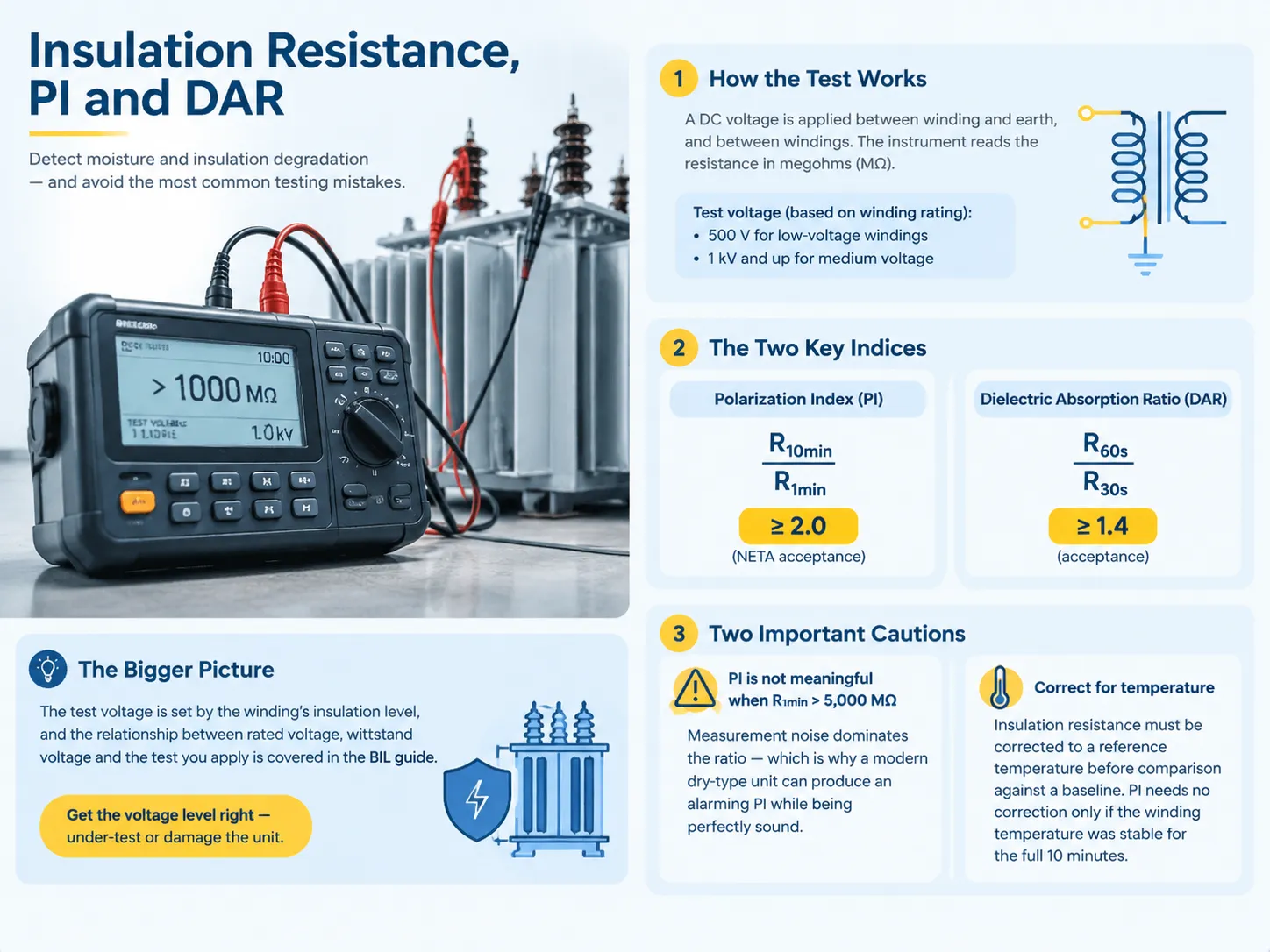
절연 저항 테스트는 절연 저항을 결정하기 위해 모든 권선에 대해 허용되는 전압에서 DC를 사용하는 것을 기반으로 하며, 일반적으로 저전압 권선에는 500 V의 값이 사용되고, 중전압 권선에는 1 kV 이상의 값이 적용됩니다. 현대의 고체 상태 장치는 이 작업을 쉽게 수행할 수 있게 하지만, 실제 어려움은 얻어진 결과의 해석에 있습니다.
그러나 실제 중요성은 다른 두 매개변수로 넘어갑니다. 편극 지수(PI)는 10분 간격의 저항 값을 1분 간격의 저항 값으로 나눈 값으로 정의되며, 이 값은 최소 2.0으로 인정됩니다. 유전 흡수 비율(DAR)은 60초의 저항 값을 30초의 저항 값으로 나눈 값으로 정의되며, 최소 값은 1.4여야 합니다.
그러나 PI와 DAR의 존재는 몇 가지 실용적인 고려 사항이 무시되면 중요성이 떨어집니다. 첫 번째로 고려해야 할 중요한 점은 1분 저항 값이 5,000 MΩ를 초과할 경우 PI 측정이 허용되지 않는다는 것입니다. 왜냐하면 어떤 측정 오류도 결과를 지배하지 않기 때문입니다.
테스트 전압 자체는 권선의 절연 수준에 의해 설정되며, 정격 전압, 내전압 및 적용하는 테스트 간의 관계는 자체적으로 설명해야 할 주제입니다. 기본 절연 수준(BIL). 수준을 잘못 설정하면 장치를 과소 테스트하거나 손상시킬 수 있습니다.
유전 내전압, 부분 방전 및 임펄스
위에서 언급한 테스트는 절연이 네트워크가 제기할 수 있는 모든 도전을 견딜 수 있음을 보여줍니다. 이러한 테스트는 공장 표준 테스트이며, 더 큰 변압기에 대한 테스트를 수행하고자 할 경우 다양한 장비를 사용하여 현장에서 반복할 수 있습니다.
- 전력 주파수 내전압 테스트. 테스트 대상은 특정 시간 동안 특정 테스트 전압에 노출되며, 전압은 테스트 값의 1/4에서 시작하여 값까지 점진적으로 상승합니다. 합격 기준은 테스트 중에 파괴 또는 아크가 발생하지 않는 것입니다. 테스트 중 사용되는 표준은 IEC 60076-3에 규정되어 있습니다.
- 낙뢰 임펄스 테스트. 이 테스트는 특정 전압 클래스에 대한 낙뢰를 모방하기 위해 1.2/50 µs 임펄스를 모방합니다.
- 부분 방전 측정. 이 테스트는 내전압 테스트로는 일반적으로 감지되지 않는 국부 절연 고장을 위한 PD 측정을 수행합니다. 일반적으로 새로운 변압기에 대한 허용 값은 명목상 상-접지 전압에서 약 10 pC입니다.
이 모든 테스트는 파괴적인 테스트입니다. 현장에서 수행할 때 즉흥적으로 행동하지 말고, 명판에 명시된 전압보다 큰 전압으로 서비스 연한이 지난 장치를 테스트하지 마십시오.
무부하, 부하 손실 및 임피던스
세 가지 테스트는 변압기의 설계 측면에서 전기적 특성을 평가합니다.
자극(무부하) 테스트의 감독으로 인해 한 권선에 정격 전압이 적용되는 동안 다른 권선은 차단되어 전압, 전류 및 전력 측정을 가능하게 합니다. 유도 전류가 너무 높으면 일부 권선의 단락 또는 코어의 고장으로 인해 내부 회로에 문제가 발생했음을 나타냅니다. 삼각형 코어 유형을 사용하는 변압기의 경우 외부 정착의 값이 코어 자체의 판독값보다 커야 하며, 그렇지 않으면 문제와 예상되는 고장을 나타냅니다.
부하 손실 및 임피던스를 평가할 때 변압기의 권선이 단락되고, 전원 공급 장치가 정격 전압을 제공하여 정격 전류에 도달합니다. 이렇게 계산된 임피던스 값은 이름판에 표시된 값과 비교되며, ±7.5%의 편차가 허용되어야 두 권선 공장에서 벗어나지 않습니다. 변압기의 실제 사용에서 임피던스 계수의 중요성을 강조할 필요가 있으며, 이는 향후 전체 장치의 효율성에 영향을 미치는 주요하고 결정적인 요소입니다.
오일 테스트 및 용해 가스 분석
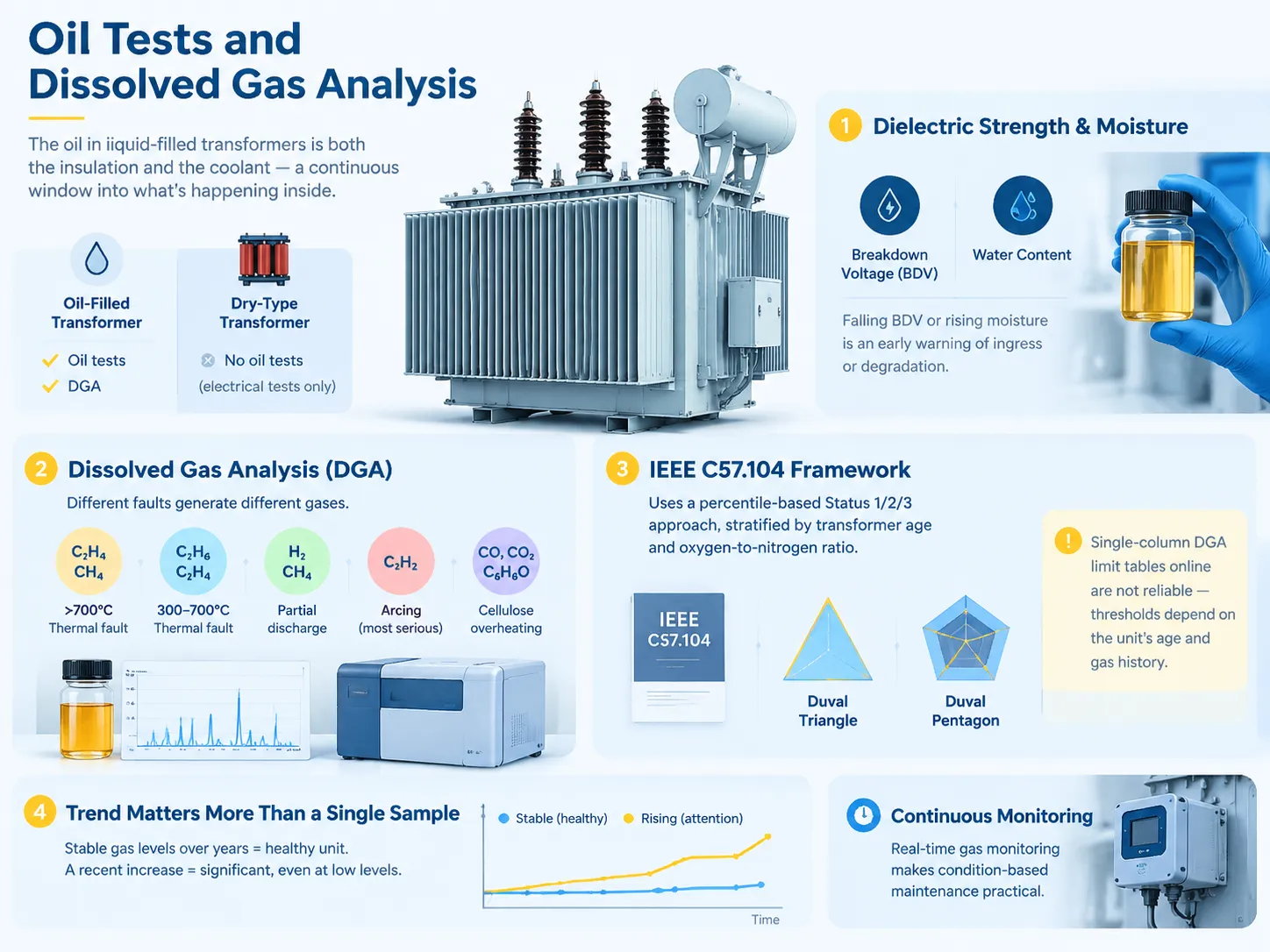
오일로 채워진 변압기에서 오일은 절연체이자 냉각제로 작용하므로 변압기 탱크에서 발생하는 일을 지속적으로 나타내는 지표입니다. 건식 변압기의 경우 오일이 없으므로 오일 테스트가 없습니다. 따라서 테스트는 전기적 수단에만 의존합니다.
유전 강도 및 습기 테스트. 오일 테스트는 파괴 전압 및 습기 함량 테스트를 포함합니다. 오일의 BDV가 감소하거나 습기가 증가하면 변압기 내부에 물이 침투했거나 오일이 열화되었음을 나타냅니다. 다행히도 이 두 가지 매개변수는 측정하기에 저렴합니다.
Dissolved gas analysis. DGA is by far the most advanced measure for oil immersed transformers and it works because various faults produce different gases. For example, thermal faults above 700 degrees Celsius generate ethylene and methane; for thermal faults between 300 and 700 degrees Celsius, ethane and ethylene are produced; partial discharge is characterized by the presence of hydrogen and methane while arcing results in generating of acetylene which is known to be a serious indication of the fault; as for overheating of cellulose, it is characterized by carbon monoxide, carbon dioxide and furfural.
Interpretation is outlined by IEEE C57.104 which is currently based on percentiles rather than total combustible gas content. Other methods that can be used include Duval triangle and pentagon. That is the reason why there is no point in using any tables available online in terms of DGA limits, as the limits are determined by the specific equipment’s age and gas history.
Trend is much more important than a single sample. If gas readings are stable for many years, this is a good sign even if the values are high. On the contrary, increase in readings is alarming even if the readings are not high. This is the reason why the testing should be done on a regular basis and compared to previous data during each testing.The monitoring practice that makes this practical, including continuous gas monitoring instead of periodic sampling, is described in this overview of real-time transformer gas monitoring for condition-based maintenance.
Polarity, Vector Group and Phasing
This testing will show that the transformer has been hooked up in accordance with the information given on the nameplate, ensuring safety of parallel operation. The single-phase polarity test is used to determine whether the winding is of additive or subtractive polarity. The three-phase phase relation test confirms the vector group and phase sequence of the transformer. Mismatching polarity or vector groups of two transformers being operated in parallel results in the generation of a current that is strong enough to burn both transformers. Hence, this is a critical stage of commissioning.
Reading the Numbers: Pass, Investigate or Stop
| 테스트 | Typical acceptance | Investigate | Stop and diagnose |
|---|---|---|---|
| Turns ratio (TTR) | Within ±0.5% of nameplate, all taps | Any consistent deviation | Single phase off, or no reading |
| 권선 저항 | Balanced phase to phase, matches factory report | A few percent spread | One phase clearly high or drifting |
| 절연 저항 | Above the baseline for the class | Falling trend against previous tests | Below the minimum for the voltage class |
| 편극 지수 | ≥ 2.0 | 1.5–2.0 | Near 1.0 (unless 1-minute IR exceeds 5,000 MΩ) |
| 임피던스 (%Z) | Within ±7.5% of nameplate | Modest deviation | Large deviation — likely winding deformation |
| DGA | Status 1, stable trend | Rising trend or Status 2 | Acetylene present, or Status 3 |
| Oil BDV | Above the specified minimum | Falling against baseline | Low enough to compromise insulation |
What should be done when the tested unit failed is to explain why it failed instead of making a judgement about it. If a unit shows excessive ratio because a wrong tap was used, it can be fixed in five minutes. If a dry-type unit shows somewhat low PI while possessing very high IR value, it indicates the presence of measurement noise, not degradation.Diagnostic discipline at this stage is what stops a serviceable transformer being scrapped on the strength of one number, and the systematic route through the common failure modes is set out in this guide to troubleshooting power transformer faults.
How the Test Battery Changes by Transformer Type
The basic electrical tests are universal. The only thing that changes is the details and the stress given.
- Distribution transformer (with oil). The entire battery of electrical tests plus oil BDV, moisture and DGA. The standard tool for roadside and pit-type transformers
- Dry transformers. The same battery of electrical tests but without the oil tests. For dry-type machines, the procedures are automatic and described here in the dry-type transformer routine tests description. PD measures are quite significant because there is no oil to test.
- Large power transformers. In addition to all the electrical tests mentioned above, the insulation power factor test (in GST, GSTg, UST versions), capacitance test, bushing power factor test against nameplate C1 parameter; SFRA method for everybody will be added.
- Instrument transformer. Ratio and polarity checks, and also accuracy class testing are to be performed according to their own standards, not according to that of the large power transformers.
- Small and single-phase transformers. Simple tests are usually enough: continuity test, resistance test, ratio test, voltage test.
Safety Rules That Are Not Optional
Discharge after every DC test. TTR, insulation resistance and power factor tests all charge the winding and a winding retains this charge, like a capacitor, after disconnection. It must be grounded using a grounding stick immediately after testing and kept grounded until next step. This is how technicians can get shocked by a deactivated meter.
Prior to carrying out any resistance or continuity measurement isolate and lockout. The meter can be destroyed, and operator can be hurt if an ohmmeter is used on a powered circuit.
Unplug surge protectors, protective relays, and control circuits before testing insulation resistance. High voltage will damage them.
PPE must correspond to the voltage class according to NFPA 70E standards and the results of the arc flash study conducted at the facility, not to the tradition.
자주 묻는 질문
How to test if a transformer is working?
To check a smaller transformer, first isolate it, conduct winding continuity checks and DC resistance measurements on it using a multimeter, and then apply the rated AC voltage to its primary side and verify that the secondary side reads almost the rated voltage on it. For larger transformers, the passed field check consists of a turns ratio test on every tap that is within ±0.5% of nameplate specification, insulation resistance measurement yielding a polarization index higher than 2.0, and visual and thermal inspections under load. In case of oil-filled transformers, the boil dielectric strength test and dissolved gas content test are also required. The term “working” means that all said above have passed rather than the secondary having some kind of voltage on it.
What are the methods of testing a transformer?
There are prominent electrical methods including turns ratio (TTR), winding resistance, insulation resistance using polarisation index and dielectric absorption ratio, insulation power factor or tan delta, applied voltage (power frequency withstand), lightning impulse, partial discharge, excitation or no-load loss, load loss with short-circuit impedance, polarity and phase relationship etc. In terms of mechanical or chemical methods, SFRA and oil dielectric strength moisture testing and dissolved gas analysis can be used for transformers. The choice of method depends on the type of transformer, size and stage of its life.
How to test a 12V transformer with a multimeter?
Make sure that the transformer is disconnected from loads. Set the meter to ohms and measure the resistance across the primary: it must show positive resistance, not an open circuit and its value should be greater than that of the secondary winding since the latter usually consists of thicker wire and has fewer turns. If the transformer can be used with mains supply on the primary, supply the transformer with the rated voltage and measure the secondary voltage with the meter set to the AC volts — the meter must read close to 12 Volts without load and may show a little higher voltage. If the readings are half or double the expected value, the readings have been taken from some other winding. Do not connect mains to the transformer if its primary circuit rating is unknown.
How to test a transformer with a multimeter without power?
Checking continuity and DC resistance without power only is possible. Using the two meters you need to check winding by winding. If your reading is infinite ohms, you have an open circuit problem in the winding or lead. If the reading is almost zero while in winding having considerable resistance, you have a short circuit. By comparing primary and secondary resistance, you can figure out whether the unit is step-down transformer and how it is wired in general. However, you cannot establish turns ratio, insulation resistance between the windings or locate a single shorted turn.
How to test a transformer with a megger?
The next step is to isolate the transformer as completely as possible. Disconnect the surge arresters, protection relay and control electronics first. Decide on the test voltage for winding insulation class — low voltage windings have 500 V DC, and medium voltage has 1 kV or higher. Winding to earth is measured first, and then winding to winding. Ensure the test is conducted for the full duration — don’t just read the needle right away. Polarization index is obtained from the reading done after 1 min and 10 min; NETA acceptance is above 2.0, dielectric absorption ratio is above 1.4. Also remember to adjust your raw insulation resistance for temperature before comparing it with the baseline values.
Can I test a transformer without disconnecting it?
Although it is possible to apply ratio and continuity tests to a circuit that has been disconnected, in the case of insulation testing, the insulation resistance test applies a high voltage direct current which results in damaging any equipment that may be connected. Thus the disconnection of the circuit is not simply a procedure but a necessary prerequisite for making such tests valid.
참고 문헌
- International Electrotechnical Commission — IEC 60076 series, Power transformers
- IEC Webstore — IEC 60076-15, Power transformers, Part 15
- IEEE Standards Association — IEEE C57.12.90 test code, IEEE 62 field diagnostics, IEEE C57.104 DGA
- UL Standards & Engagement — UL 1562, Transformers, Distribution, Dry-Type
- UL Solutions — transformer and electrical equipment testing services
결론
The tests on a transformer follow a specific order, and it is this order that makes them dependable. First comes the visual inspection, and then comes the dead tests followed by the live tests, with the winding always discharged after each DC test and all measurements taken and kept as reference.
When it comes to transformer testing, there are essentially three points that must be taken into consideration. A transformer needs to be tested according to its specific characteristics. A control transformer would need only a multimeter and a turns ratio test kit while a 1MVA transformer would require equipment that is completely different from that. A qualitative comparison of the data should be done, rather than relying on some absolute figures — the turns ratio should be within ±0.5 percent of the nameplate reading, winding resistance should be well balanced among phases and must match factory specs, and PI should be above 2.0 only to realize that at higher resistance levels this indicator has little or no meaning anymore basically.
Moreover, the tests need to be conducted in a specific order making sure to record everything and discharge the winding after each and every DC test. The majority of transformer issues are visible way before they actually happen.