When a textile manufacturer in Bangladesh adopted cutting-edge machinery from Japan, this machinery was built to perform on a nominal 200 volts, three phases. However, the factory’s local supply was 400 volts, three phases, as is standard in South Asia. A typical step-down transformer would have modified the factory supply from 400 volts to 200 volts, since the factory supply was spotty, and the voltage sagging down to a maximum of 370 volts at peak periods created problems for the 200-volt machines. It was clear that a simple step-down transformer wouldn’t work here. What was needed instead was a booster transformer with a tapped secondary winding. Such a transformer provides a means of adding or subtracting a percentage of the primary voltage and thus changing parameters in order to compensate for sagging voltage. The booster transformer was set up to provide an additional 10 percent of incoming voltage, providing a steady 200-220 volts for the weaving machines regardless of any fluctuations in the supply. The problem with under-voltage and overheating issues ceased, and the factory returned to normal performance.
요약: A booster transformer is utilized to modify voltage supply within an acceptable range of +5% to -20%, while only processing the modified portion of the power; therefore, it is much smaller and cheaper compared to a standard transformer of an equal load kVA. The most suitable solutions for the international market are pre-configured standard buck-boost transformer units used for voltage correction, customized transformers for industrial and non-standard applications, and integrated voltage regulation equipment with auto switchers for the cases of supply instability.

What a Booster Transformer Does — and How It Differs from a Standard Step‑Down or Step‑Up Transformer
Regardless of the fact whether they raise or lower voltage, just about every transformer is made from a primary winding, a secondary winding, and a magnetic core. The difference between the primary and secondary windings is that they are not connected electrically, while the secondary winding voltage is a certain fixed proportion of the primary one, which is defined by a turns ratio. If the primary voltage changes, the secondary one automatically changes as well. There is no point in expecting the transformer to regulate the input voltage: it does not do anything but pass the input voltage fluctuations to the output. The operation principle of booster transformers, however, is different. Such transformers are connected in a way that their secondary voltage will be either added to or subtracted from the primary voltage, thus achieving the output voltage that differs from the input voltage by a specific value. Moreover, booster transformers are not intended to convert all of the load electricity from one voltage to another: their application is limited to adjusting a slight mismatch between voltages. For instance, a booster transformer can change an input 208‑volt voltage into an output 240-volt one, or convert 480 volts into 416 volts, or hold an output 400 voltage when given an input of only 370 volts, etc.The major economic benefit of a booster transformer is that you do not have to purchase a transformer capable of handling all the load. The booster transformer, instead, only needs to be capable of handling the difference between the required voltage and the actual supply voltage.
The standard connection for a booster transformer is the autotransformer in which a single coil serves both as input and output. The coil has a tap from which the output voltage is taken between the end of the coil and the tap. The autotransformer is very efficient in construction as it requires less copper, less steel for core and less insulation, compared to other isolating transformers. However, it does not provide galvanic insulation between the input and the output; they are connected through a common conductor and any fault that occurs on the input will be observed on the output. However, this may not be a problem for many applications in industries because the equipment already has circuit breakers and isolation is not a safety or functional concern. The buyer must be aware of this limitation and agree to it. When galvanic isolation is required by the application (for instance, in a hospital, in the laboratory or in circuits that require the output to be floating with respect to the ground) the buyer should ask for a separately designed booster transformer that has isolating winding.
Besides the autotransformer one can use a two-winding transformer. This variant provides the same advantages as mentioned above, but it has a fully isolated winding. The isolated booster transformer has the same ability to correct voltage (by adding or subtracting a percentage from the input voltage) but at the same time ensures galvanic isolation. Isolated designs are intended for use in medical diagnostics equipment, laboratory instruments sensitive to ground noise, circuits where there is a need for float condition of the output. But the isolated booster transformer has its disadvantages — size, weight and cost. So it is approximately 50-80% bigger and heavier than the autotransformer of the same kVA rating, which means that the buyer pays more for it. Buyers who need galvanic isolation must realize this trade-off should they purchase isolated transformer; buyers who do not need separation must look for other solution.
For an introduction to the full range of transformer types and their specific applications, see the product catalogue at 수비안 전기, which includes booster transformers, isolation transformers, distribution transformers, and specialty power transformers for the global market.

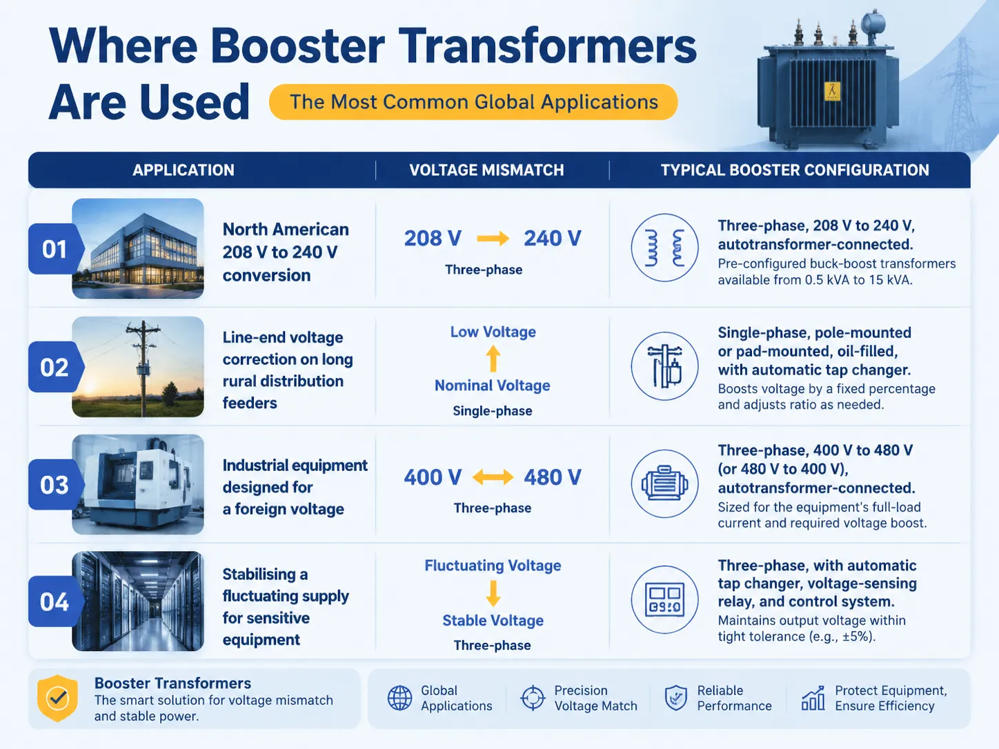
Where Booster Transformers Are Used: The Most Common Global Applications
아래 표는 가장 일반적인 절연 변압기의 응용 분야를 요약합니다. booster transformers across different industries and regions, the voltage mismatch that the transformer corrects, and the typical configuration that is specified.
| 응용 | Voltage Mismatch | Typical Booster Configuration |
|---|---|---|
| North American 208 V to 240 V conversion | A commercial building or a light industrial facility is supplied with 208 V three‑phase from the utility, but the HVAC equipment, the compressors, or the machine tools require 240 V. The 32‑volt difference cannot be corrected by a standard transformer; it is a classic booster application. | Three‑phase, 208 V to 240 V, autotransformer‑connected. Standard pre‑configured buck‑boost transformers are available from every major North American electrical manufacturer for this specific voltage combination, in ratings from 0.5 kVA to 15 kVA. |
| Line‑end voltage correction on long rural distribution feeders | A customer at the end of a long distribution feeder receives a voltage that is below the nominal value, particularly during peak load periods. The utility installs a booster transformer on the pole or on a pad to raise the voltage to the nominal level. | Single‑phase, pole‑mounted or pad‑mounted, oil‑filled, with an automatic tap changer. The transformer boosts the voltage by a fixed percentage, and the tap changer adjusts the ratio as the incoming voltage varies. |
| Industrial equipment designed for a foreign voltage | A factory in a 400‑volt country (most of Europe, Asia, Africa) imports a machine that was designed for 480 volts (North America), or a factory in a 480‑volt country imports a machine that was designed for 400 volts. The voltage mismatch is typically 10–20%, which is within the range of a booster transformer. | Three‑phase, 400 V to 480 V (or 480 V to 400 V), autotransformer‑connected, sized for the machine’s full‑load current and the percentage voltage boost. The transformer is typically installed in the machine’s control panel or in a separate enclosure adjacent to the machine. |
| Stabilising a fluctuating supply for sensitive equipment | A data centre, a laboratory, or a medical facility has equipment that cannot tolerate a voltage variation of more than ±5%, but the local supply varies by ±10% or more. A booster transformer with an automatic tap changer, or an integrated voltage regulation package, corrects the variation. | Three‑phase, with an automatic tap changer, a voltage‑sensing relay, and a control system. The transformer monitors the input voltage and adjusts the boost ratio to maintain the output voltage within the required tolerance. This is the premium booster solution, and it is more expensive than a fixed‑ratio unit but provides the voltage stability that the equipment requires. |
How to Size a Booster Transformer Correctly
Determining the size of a booster transformer differs from determining the size of an ordinary isolation transformer through the fact that the former only works with equality of the portion being boosted and not the entire load. The process of sizing the transformer is as follows. Start with estimating the load current, meaning the maximum amount of current being drawn by the load in question. Given that at readiness, the equipment would only draw a certain amount, that information can be acquired from the equipment or arrived at through simple calculations, having the kVA or wattage of the equipment before you. Next, you need to understand what the amount of boosting is – how much more voltage is needed to achieve the output value you have assigned. For instance, if you get 208 V at the input and expect to have the voltage of 240 V at the output, you are going to have 32 V of boosting value. If the input changes, then the calculation has to be made taking the lowest possible value.
Upon determining these variables, you will be able to figure out kVA of the booster transformer using the following formula:Booster kVA = (Current in amps × Boosting voltage in volts × √3 for three-phase)/1,000.In the case of three-phase 50 amps load and boosting value of 32 V, the final kVA of the transformer will equal kVA = (50 × 32 × 1.732)/1,000 = 2.77 kVA.
Then, you must check the next available kVA rating, which may be usually higher than yours. In this situation, the smallest transformer you can find will have the kVA rate of 3. Thus, the customer who makes a mistake of selecting 20.8 kVA instead of 2.77 would pay a lot more than necessary just for nothing.For help with the specific calculation for any voltage and load combination, the application guides published by manufacturers such as 이튼 가장 큰 슈나이더 일렉트릭 provide detailed sizing tables and examples, and the technical support team at 수비안 전기 can assist with the selection of the correct booster transformer for any application.

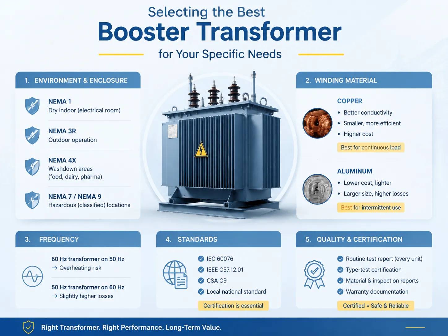
Selecting the Best Booster Transformer for Your Specific Needs
In determining which booster transformer is the most suitable for a specific project, beyond the necessary sizing calculation, many other factors come into play. The type of enclosure as well as the environmental rating should correspond with the location: NEMA 1 enclosure is suitable for a dry indoor electrical room; NEMA 3R enclosure has to be used for outdoor operation; NEMA 4X stainless‑steel enclosure is required for washing areas in food, dairy, or pharmaceutical plants; NEMA 7 or NEMA 9 are the specification for any hazardous (classified) locations in which flammable gases, vapours, and dusts can be present. The material of the windings — be it copper or aluminium — determines the size of the transformer, its efficiency, and its price. Copper windings are better in terms of conductivity and thus lead to the smaller and more energy-efficient transformer, whereas copper costs more than aluminium. The transformer with aluminium windings is cheaper and lighter than the one with copper, however, its size and energy losses are bigger. When the device is normally loaded, the energy savings that copper provides outweigh its price; however, for a transformer periodically used, it makes sense to use aluminium. The frequency must be specified correctly: the transformer created for 60 Hz will overheat if used for 50 Hz at the same voltage, because a bigger core is needed to avoid saturation. The frequency of 50 Hz transformer can be used at the frequency of 60 Hz without overheating, yet the losses will be increased slightly. Finally, the relevant standard (IEC 60076, IEEE C57.12.01, CSA C9, or a local national standard) should be determined, since it provides for the control procedures and documentation that manufacturer has to deliver. Therefore, an uncertified transformer will be rejected regardless of its performance specifications.
For a global buyer who deals with suppliers from all over the world, acquiring certified and tested equipment is far more important than getting its electrical specifications. The respected manufacturer is obliged to provide the document of routine test report for each transformer. In case of purchasing custom-designed transformer or large quantities of products, type-test certification from independent laboratory, warranty reports for the core and winding materials, as well as manufacturing inspection report is required. A buyer who purchased a transformer without all of them gets engaged in a hazard.
자주 묻는 질문
What is the difference between a booster transformer and a step‑up transformer?
A step-up transformer raises voltage at a specific ratio or a level, for instance, voltage can be raised from 240 V to 480 V correcting it to the proper level of output voltage. A booster transformer can increase or decrease the voltage level by a low percentage between 5% to 20%. It is built to cope only with that boosted part of load energy but not with the full load. Booster type transformers are usually less in size, weight and prices than the step-up transformersсaution.
Can a booster transformer be used in reverse to reduce voltage?
Yes. A booster transformer can be used to decrease or reduce the voltage instead of increasing it. A transformer with the same taps can also be applied in a different way to apply the secondary voltage to boost or to reduce it from the primary. Different connections are shown in the wiring diagrams where the installer can choose which connection will be used in the application.
Does a booster transformer provide electrical isolation?
A booster transformer that is configured as an autotransformer — with a single winding serving as both the primary and the secondary — does not provide electrical isolation between the input and the output. If the application requires isolation, a booster transformer with an isolating (two‑winding) design must be specified, and the autotransformer connection must not be used. The buyer must confirm the isolation requirement before ordering the transformer.
What is the typical lead time for a custom booster transformer?
A custom designed transformer (defined as a transformer that is built according to particular requirements regarding input and output voltage values, kVA ratings or environmental specifications) is usually manufactured with a lead time of 8 to 14 weeks after getting the manufacturing drawings approved. On the contrary, a standard transformer that is available in stock or with a lead time of 1 to 3 weeks from big electrical companies, is a transformer designed for common voltage limits such as 208 V or 240 V.
참고 문헌
- Eaton — Buck‑Boost Transformer Application Guide. Manufacturer of standard and custom booster transformers, with detailed sizing tables, wiring diagrams, and application guidance for the most common voltage combinations.
- Schneider Electric — Voltage Correction Transformers. Manufacturer of booster and buck‑boost transformers for the global market, with technical documentation covering the autotransformer connection, the sizing methodology, and the installation requirements.
- IEEE C57.12.01 — 건식 배전 및 전력 변압기에 대한 일반 요구 사항 표준. The IEEE standard that defines the design, testing, and performance requirements for dry‑type transformers, including booster and buck‑boost units.
- IEC 60076 — Power Transformers. The international standard series that defines the design, testing, and performance requirements for power and distribution transformers, adopted across Europe, Asia, Africa, and the Middle East.
The best boosting transformer for a global client is the one which is properly sized for the load electrical current and the boost voltage, properly configured for the inputting and outputting voltage and correctly specified for the installation environment and the required certification levels. A standard, pre-configured buck-boost transformer, available in stock from a renowned manufacturer or a specialized supplier is the best solution for widespread voltage-correction applications — 208V-240V, 240V-208V, 480V-600V – accounting for most of the understanding of installing booster transformers in the world. A custom-engineered solution manufactured by a company having capabilities to manufacture various models required by big industry, an unusual voltage or a harsh working environment is the right option if standard solutions do not suit the needs. For the client who needs a partner in recognizing the problem of specifications, sizing, and selecting, Subian Electric offers buck-boost transformer of all ratings, voltages, and frequencies along with certification required to satisfy the needs of the client. The point is that a transformer compensating for power mismatch costs a stone’s throw, but protects much more expensive equipment of the user relying on the power provided by the transformer.