


패널 빌더는 15 kVA의 용량을 가진 변압기를 받습니다. 변압기는 480볼트에서 작동하며 단상 연결을 가지고 있지만 프로그래머블 로직 컨트롤러와 네 개의 서보 드라이브의 상류에 설치된 후 6개월 동안 쓸모없는 장비가 됩니다. 반년 후, 누군가 클램프 미터를 사용하여 분석을 수행하고 중성 도체에 11암페어의 삼중 고조파 전류가 존재함을 발견합니다.
변압기에는 결함이 없었습니다. 일반 용도로 사용하기 위해 선택되었기 때문입니다. 따라서 이것은 산업 자동화 분야에서 가장 자주 발생하는 문제입니다.
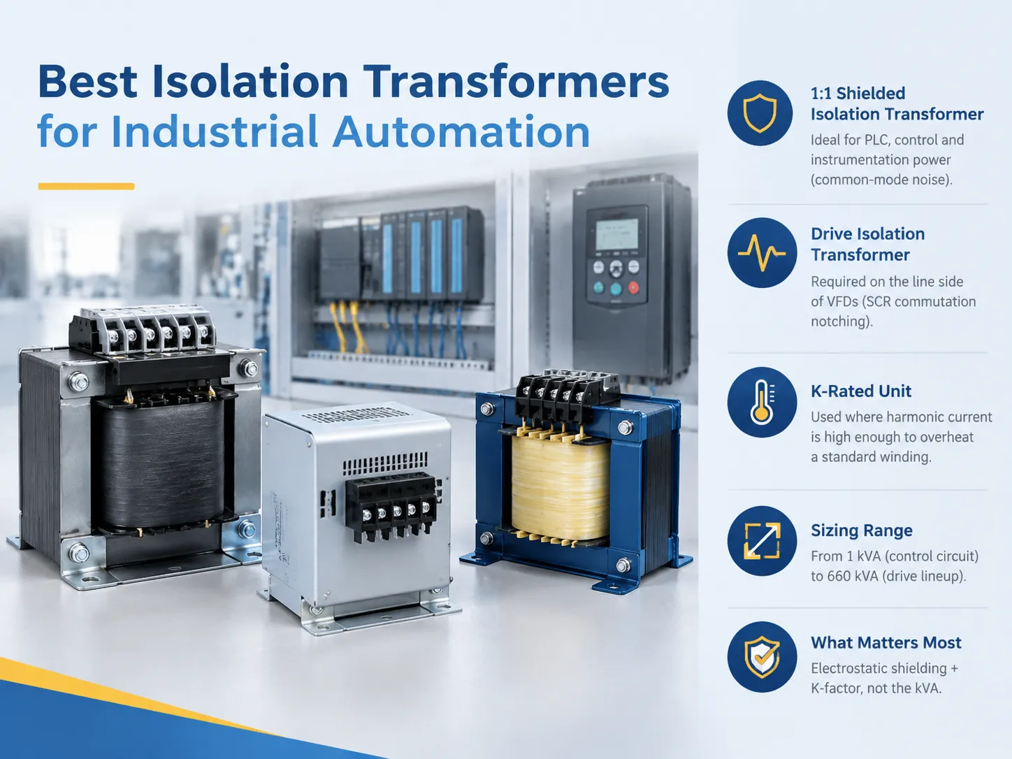
산업 자동화에 적합한 절연 변압기는 전압이 아닌 부하에 따라 달라집니다. PLC, 제어 및 계측 전력에는 1:1 차폐 절연 변압기(Hammond Power Solutions, SolaHD, Acme 및 Rex Power Magnetics에서 제공)가 필요하며, 드라이브 절연 변압기는 SCR 통신 과정에서 발생하는 노칭으로 인해 VFD의 라인 측에서 사용해야 합니다. 고조파 전류가 일반 권선의 과열을 초래할 만큼 충분히 강한 경우 K 등급의 절연 변압기가 필요합니다. 전력 범위는 제어 회로의 경우 1 kVA에서 드라이브의 경우 660 kVA까지이며, 가장 중요한 사양은 정전기 차폐 및 K 등급 요소이며, kVA 등급이 아닙니다.
절연 변압기가 실제로 하는 일
모든 변압기는 갈바닉 절연을 제공합니다. 두 개의 권선이 자기 코어를 공유하고 1차와 2차 사이에 금속 경로가 없기 때문에, 강하 배급 변압기는 이미 구매자가 구매하고 있다고 생각하는 절연 장치입니다.
절연 변압기는 권선 사이에 구리 또는 알루미늄 호일로 만들어진 정전기 차폐가 있기 때문에 그렇게 라벨이 붙습니다. 그 차폐가 없었다면 권선 사이의 정전 용량이 매우 높은 주파수의 잡음이 장벽을 넘도록 허용했을 것입니다. 전기에 존재하는 공통 모드 과도 현상은 1차 측에서 온 것과 동일한 형태로 2차 측에 도달하게 됩니다.
차폐는 안전한 처리를 위해 에너지를 지구로 전달함으로써 이러한 일이 발생하는 것을 방지합니다. 차별 잡음의 필터링을 제공하지 않으며, 전압을 조절하지 않고 번개 서지를 제거하지도 않습니다. 세 가지 다른 장치가 있다는 것을 명확히 볼 수 있지만, 시장 브랜드는 모두 이를 하나의 제품으로 분류합니다.
그러한 차폐된 절연 변압기에 대한 정확한 설명은: 공통 모드 잡음을 약 1 KHz 이상의 주파수에서 필터링하면서 통과하는 전압과 전력을 변경하지 않는 변압기입니다.
혼동되는 네 가지 의무
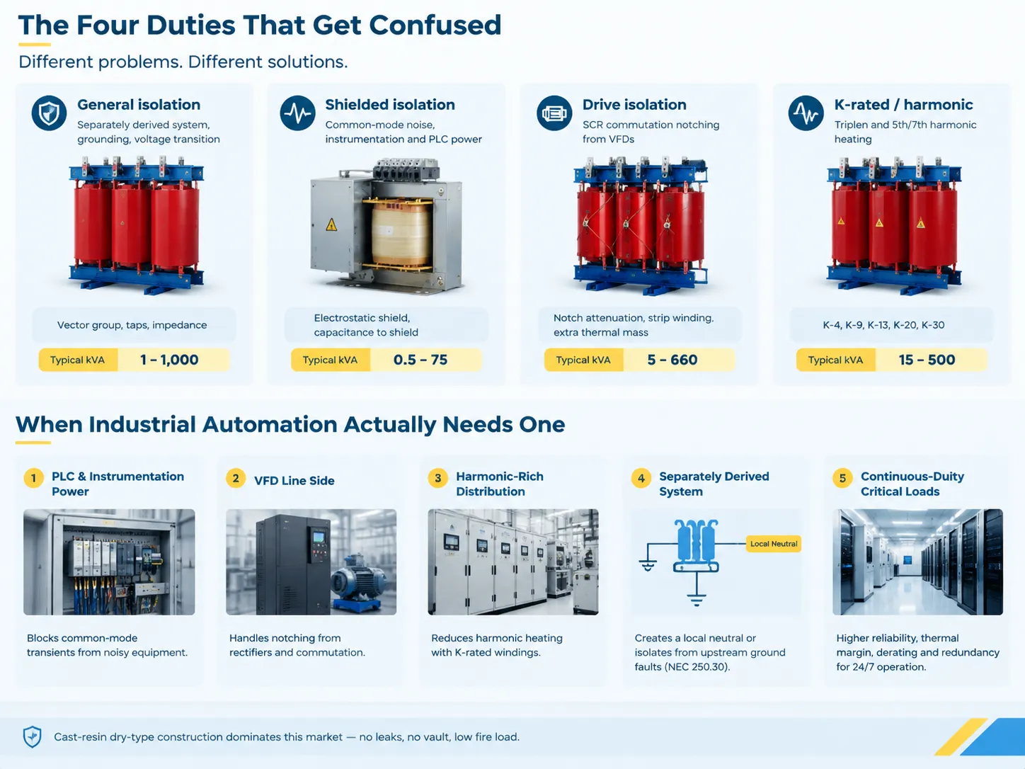
| 용도 | 해결하는 부분 | 주요 사양 | 일반적인 kVA |
|---|---|---|---|
| 일반 절연 | 별도로 유도된 시스템, 접지, 전압 전환 | 벡터 그룹, 탭, 임피던스 | 1–1,000 |
| 차폐된 절연 | 공통 모드 잡음, 계측 및 PLC 전력 | 정전기 차폐, 차폐에 대한 정전 용량 | 0.5–75 |
| 드라이브 절연 | VFD의 SCR 통신 노칭 | 노칭 감쇠, 스트립 권선, 추가 열 질량 | 5–660 |
| K-등급 / 고조파 | 삼중 및 5차/7차 고조파 가열 | K-4, K-9, K-13, K-20, K-30 | 15–500 |
지정된 네 가지 방법 중 두 가지는 매번 실질적으로 동등합니다. 드라이브 절연 변압기는 K-등급이어야 하며, 그 역할은 시스템으로서 노칭을 제거하는 것이며, VFD 시스템은 원래의 노칭과 고조파 전류를 모두 생성합니다. DIT(절연 변압기를 위한 고급 기술)가 아닌 K-등급 변압기를 구매하면 노칭 보정 없이 열 부하를 제공합니다. 반대로 K-계수를 고려하지 않고 DIT를 획득하면 침수 변압기 솔루션이 가능하지만, 권선은 과도한 온도에서 작동하게 됩니다.
주조 수지 및 건식 유형 구조는 한 가지 간단한 이유로 이 특정 사례에서 분명히 우세합니다: 누수가 없고, 금고가 없으며, 연소 부하가 너무 작아 보험사에서 문제를 제기하지 않습니다. 주조 수지 설계와 대안 간의 구조적 차이는 SCB13 유닛과 국제 주조 수지 변압기 간의 비교에서 설정됩니다., 이는 프로젝트가 수입 드라이브와 국내 배전 장비를 혼합할 때 중요합니다.
산업 자동화가 실제로 필요할 때
돈을 써야 하는 다섯 가지 상황이 있습니다. 나머지 경우에는 논의되지 않습니다.
- 많은 소음이 있는 공장에서의 전력 및 PLC 계측. 480V-120V 절연 변압기는 용접 기계, 접촉기 및 기타 드라이브로 인해 발생하는 공통 모드 간섭을 제거할 수 있는 제어 전원 공급 장치 앞에 있습니다. 이것은 실제 사례이며, 필터가 좋은 접지를 가지고 있고 2차 전선이 짧은 경우에 작동합니다.
- VFD의 라인 측. 6상 모터 작동은 매번 두 개의 상을 단락시켜 노칭 전압이 형성되어 상류 변압기에 기계적 및 열적 스트레스를 줍니다. 변압기의 적용은 스트립 도체를 사용하여 와류 손실을 줄이고 좋은 가열 여유를 가능하게 하는 방식으로 이루어졌습니다.
- 고조파 전류 분배. 변압기가 드라이브 그룹, UPS 정류기 및 LED 드라이버에 전력을 공급할 때, 결과적으로 발생하는 고조파 전류는 변압기의 kVA 등급을 참조하여 권선을 예상보다 훨씬 더 가열합니다. K-등급 변압기와 대조적으로, 고전 기술은 어느 정도 과대 설계 없이 작동할 수 있습니다.
- 파생 시스템과 관련 시작. 공장이 로컬 중성점이나 다른 접지를 필요로 하거나 접지 결함 경로를 차단하고자 할 경우, 변압기를 사용하여 NEC 250.30에 따라 이 목표를 달성해야 합니다.
- 지속적인 작동으로 중요한 장치에 전원 공급. 데이터 홀, 클린룸 및 기타 장치 주변의 전력은 모든 비즈니스에 매우 중요합니다. 실제로 어떻게 보이는지, 여기에는 감액 및 중복 선택이 포함되며, 데이터 센터를 위한 고신뢰성 건식 변압기에 대한 이 검토에서 다루어집니다., 그리고 그 이유는 연간 8,000시간 운영되는 프로세스 라인에 직접적으로 적용됩니다.
크기 조정: 대부분의 입찰에서 잘못된 산술
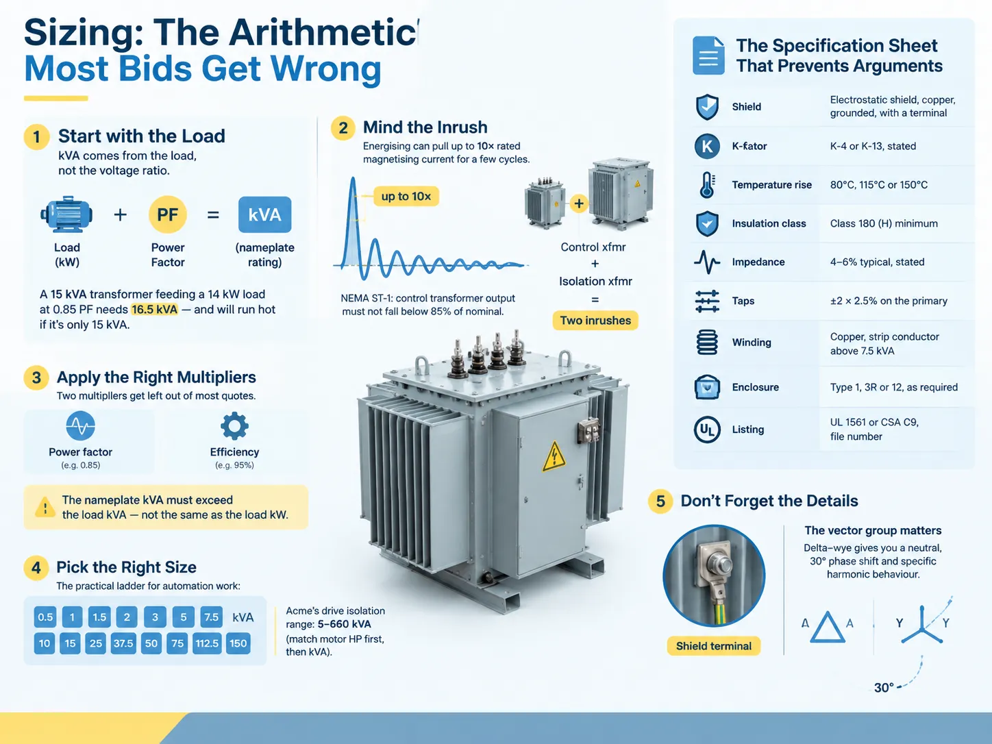
부하는 kVA를 결정하며, 전압 비율이 아닙니다. 먼저 연결된 총 부하를 확인하고, 정당화할 수 있는 모든 다양성을 계산한 후, 가장 가까운 큰 표준 크기를 선택합니다. 1:1 변압기에서는 변압기가 동일한 kVA를 전송하지 않으며, 전압 비율이 동일하기 때문입니다. 단순히 계산된 kVA를 전송하고, 전압이 동일하므로 1차 및 2차 단자에서 전류 수준을 동일하게 유지합니다.
대부분의 견적에서 누락된 두 가지 보정 요소가 있습니다.
효율성. 예를 들어, 15 kVA 변압기가 0.85의 역률을 가진 14 kW 부하에 연결되면, 16.5 kVA로 평가될 수 있으며 과열로 작동할 수 있습니다. 명판의 kVA 값은 부하의 kW 값과 다를 수 있는 부하의 kVA 값보다 높아야 합니다.
돌입 전류. 변압기가 전원이 공급되면, 자화 전류를 소비하며 이는 여러 주기 동안 정격의 최대 10배에 이를 수 있습니다. 따라서 NEMA ST-1 표준에 따르면, 돌입 과정 동안 제어 변압기의 출력은 명목값의 85%보다 작아서는 안 됩니다. 이러한 이유로 제어 변압기는 배전 변압기보다 낮은 플럭스 수준에서 작동하도록 설계됩니다. 제어 변압기가 절연 변압기에서 공급되면 다시 돌입 전류가 발생하며, 상위 회로 차단기가 이를 감지합니다.
자동화 응용 프로그램을 위한 표준 표에는 0.5, 1, 1.5, 2, 3, 5, 7.5, 10, 15, 25, 37.5, 50, 75, 112.5, 150 kVA의 값이 있습니다. Acme는 5 kVA에서 660 kVA까지의 범위를 생산하는데, 이는 대부분의 경우 DIT 프로세스가 사용 가능한 정격 전력과 설치된 모터 간의 일치를 가져오기 때문이며, 따라서 선택 표는 각각 HP와 kVA에 따라 배열됩니다.
논쟁을 방지하는 사양 시트
| 항목 | 이것을 작성하십시오 | 왜 중요한가 |
|---|---|---|
| Shield | Electrostatic shield, copper, grounded, brought to a terminal | Without a terminal you cannot verify the bond |
| K-계수 | K-4 or K-13, stated | Unstated means K-1 by default |
| 온도 상승 | 80°C, 115°C or 150°C | 150°C is smaller and shorter-lived |
| 절연 등급 | Class 180 (H) minimum | Margin against harmonic heating |
| 임피던스 | 4–6% typical, stated | Sets downstream fault current |
| Taps | ±2 × 2.5% on the primary | Corrects a supply running high or low |
| 권선 | Copper, strip conductor above 7.5 kVA | Lower eddy loss, better short-circuit strength |
| 인클로저 | Type 1, 3R or 12, as the location requires | Washdown and outdoor areas are not Type 1 |
| Listing | UL 1561 or CSA C9, file number | Inspectors ask, and so do insurers |
Most commonly, the shield terminal is disregarded. Even though a shield that has been bonded to the core as well as the core which has merged into the enclosure can carry current, it is impossible to measure the terminal before taking it apart which is often not done by many when assembling the machinery.
The vector group also deserves thorough investigation. For instance, a delta-wye transformer used to produce a separately derived system will give you neutral, 30-degree phase shift, and define the way harmonic behaviour works based on the mechanics of the circuit. This explanation of the delta–wye transformer and how it works covers the part that matters at commissioning rather than in theory.
Brands and Product Families Worth Shortlisting
In North America, four names stand out clearly. However, one is actually an established specialist rather than a catalog brand.
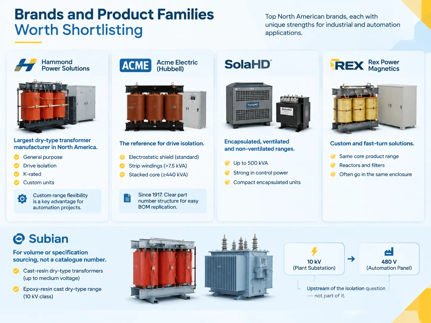
- Hammond Power Solutions, which happens to be the biggest dry-type transformer producer in North America, is known for typical transformers such as general-purpose transformers, drive isolation transformers, K-rates transformers, and customized transformers. The company’s main advantage in automation is the ability to provide a comprehensive range of customized transformers, which is necessary when a manufacturer requires 575 V input and 480 V output in a special enclosure.
- Acme Electric (Hubbell) is the main brand in terms of drive isolation. The electrostatic shield is a standard quality of the DIT series and is not an option. All transformers of above 7.5 kVA contain strip windings, whereas the ones of 440 kVA and more do use a stacked core. The company has been working on the production of such transformers since the year of 1917.
- SolaHD is a competitor of the same type of transformer. However, their product is encased and ventilated, with the non-ventilated one included in this group of products. However, in terms of control power units, their encapsulated equipment is much more powerful.
- Rex Power Magnetics has entered the same market, however, the company is known for its customized solutions and quick delivery, as well as reactors and filters that are commonly included in the same enclosure.
For buyers sourcing at volume or to a specification instead of a catalogue number, the manufacturer side looks different. Subian builds cast-resin dry-type transformers up to medium voltage, and the epoxy-resin cast dry-type range covers the 10 kV class that feeds a plant substation before anything reaches a 480 V automation panel. That is upstream of the isolation question, not part of it, and knowing where the boundary sits stops the wrong enquiry going to the wrong supplier.
Installation Details That Decide Whether It Works
If a shielded isolation transformer is mounted incorrectly, it becomes ineffective because of the unshielded version’s characteristics, and the issues involved are always the same.
Long secondary leads. Noise is induced into each meter-long section of the conductor making it possible to make use of the transformer shield only for what takes place inside the transformer. Place the transformer close enough to the load, make the secondary lines as short as possible, and do not keep them parallel to the power cables for 10 meters.
Ground loops through the shield. On the one hand, the shield needs to be grounded in one area, which means that one should not do it at both ends, otherwise, a loop antenna is created around noise. The shield must be connected to the panel not through painted metal but through a conductive lead.
Then the usual electrical checks. Overcurrent protection on both primary and secondary, bonding jumper on the secondary if the transformer creates a separately derived system and the full commissioning set including the insulation resistance check, turns ratio check, polarity check, and load test before handing it over to the customer. The sequence and acceptance values are set out in this guide to testing a transformer before energisation, and skipping the ratio check is how a reversed winding reaches a live PLC.
Mistakes That Show Up in Commissioning
- Ordering a 1:1 device when a step-down transformer is required. A 480 to 120 volt control supply is meant to perform step-down operations with the benefit of isolation; it is certainly not a 1:1 transformer. Customers ordering a 1:1 transformer along with a separate 120 V power supply would end up paying more and taking up more panel space for achieving the exact same goal.
- Assuming that the shield takes care of earth loops. It does remove common mode noise, but does not tackle the issue of the difference between two ground references.
- Disregarding sounds. A transformer installed outside the control room wall, creating 55 dB noise, becomes a ground for complaints. Core construction and isolation in mounting are given a lot of attention, but placing the unit in the corridor is no way to design it.
- Ignoring the heat. A transformer with 15 kVA power rating and 97% efficiency generates about 460 W in the enclosure. Enclosing it in the sealed cabinet based only on drive losses will cause the equipment to run 15°C above expected temperatures.
자주 묻는 질문
Do I need a 1:1 isolation transformer or a shielded step-down?
When the load voltage is different, a stepdown unit with a shield is needed instead of a 1:1 unit. If the load voltage is already the same as the supply voltage and the problem is common mode noise, the 1:1 shielded unit is the right choice. The term 1:1 represents the ratio of the unit and not its noise characteristics and the shield works for noise suppression.
Does an isolation transformer protect against power surges?
In a way, yes. The inductance lessens sharp voltage spikes, and the shield prevents noise interference but does not provide surge protection and, therefore, has no UL 1449 classification; surge protection devices are found at the point of entrance to the service, as well as in the panel of the building.
K-rated or oversized: which is better for harmonic loads?
The cleaner answer is K-rated. A K-13 unit fulfills the necessity to transport the harmonic current while maintaining the temperature rise below the rated limit. When a K-rated unit is unavailable in the required size as well as lead time, the solution is oversizing by a factor of 1.5 to 2 times without any effect on the performance but with an impact on the panel space for the gear.
Can I bond the neutral on the secondary?
When it comes to transformers that are separately derived systems, NEC 250.30 provides guidance; there must be a system bonding jumper connecting the secondary neutral to the equipment grounding conductor, either at the transformer or at the first disconnecting means, but not at both locations. In cases when the transformer is not a separately derived system, the neutral will not be bonded at the transformer. Failing to understand this can lead to the creation of a parallel ground path and an un-clearing ground fault.
참고 문헌
- Hammond Power Solutions — Dry-Type Transformer Catalogue
- Hubbell — Acme Electric Drive Isolation Transformers
- SolaHD (Emerson) — Power Quality and Control Transformers
- Rex Power Magnetics — Dry-Type Transformers and Reactors
- NFPA 70 — National Electrical Code, Articles 250 and 450
결론
The best isolation transformer for an automation panel is not necessarily the most costly. Rather, it is the one that has characteristics matching the load: shielded from noise, drive-rated for notching, K-rated for harmonics, and sized from kVA, rather than voltage ratios.
Just four lines of specification will determine whether a certain unit does anything useful at all. First is a shield with a terminal to measure. Second is that the K factor is stated. Third is that the temperature rise is stated. Finally is the proximity of the mounting site to the load so that any potential for malfunction through design failure is minimized.