


В отличие от распределительных трансформаторов для коммерческих целей, трансформаторы для дата-центров имеют уникальную задачу: они должны располагаться близко к нагрузке, которую они поддерживают, будут работать непрерывно с высокой степенью выполнения задачи и смогут справляться с нагрузкой, отличной от синусоидальных волн. Указанное выше требование делает использование трансформаторов с масляным заполнением невозможным из-за опасности возгорания и определяет три особые характеристики трансформаторов: гармоническую производительность, тепловой запас и частичное разряд, которые определяют, будет ли он работать двадцать лет или восемь.
В двух словах: Для подключения питания дата-центров подходит выбор трансформатора сухого типа с отливкой из смолы с термоизоляцией класса H (180 °C), рейтингом K-фактора не менее K-13 (обычно K-20), импедансом 6%, векторной группой Dyn11 для входа ИБП, значением частичного разряда менее или равным 10 пК при 1,1× номинальном напряжении и в соответствии с DOE 2016 или EU Ecodesign Tier 2 с точки зрения производительности. Типичные мощности трансформаторов для дата-центров находятся в диапазоне от 500 кВА до 3 750 кВА при 10 кВ и 35 кВ соответственно.
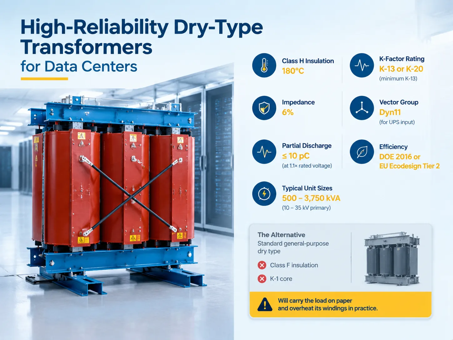
Почему дата-центры используют сухие трансформаторы в первую очередь
Основным фактором является пожарная безопасность системы. Обмотки из смолы могут самозатухать и не содержат горючих жидкостей, поэтому трансформатор может быть установлен в здании близко к нагрузке, которую он обслуживает. Таким образом, нет необходимости в масляной яме, защитной стене или специальном отсеке с хорошими огнеупорными свойствами. Трансформатор размещается вблизи ИТ-оборудования в колокационных или корпоративных дата-центрах, где каждый квадратный метр свободного пространства ценен; следовательно, расстояние прокладки проводов низкого напряжения уменьшается.
Следующим движущим фактором являются требования к обслуживанию. Нет необходимости контролировать уровень масла, газовый реле или сушить воздухоотводчик. Вместо этого необходимо контролировать только частичный разряд и температуру, что проще по сравнению с процессом химии жидкости.
С другой стороны, сухие трансформаторы плохо переносят тепло. Масло движется и помогает удалять тепло от обмоток, в то время как смола этого не делает. Таким образом, класс изоляции, повышение температуры и гармоники становятся гораздо более важными в случае сухих трансформаторов, так как расстояние между нормальной работой и повреждением изоляции значительно меньше.
Три спецификации, которые решают все
Класс изоляции и повышение температуры
Согласно ANSI/IEEE C57.12.01, сухие трансформаторы обычно имеют рейтинг 80, 115 или 150 K повышения температуры при температуре окружающей среды 40 градусов Цельсия для изоляционной системы 220 градусов Цельсия. Таким образом, более низкое повышение температуры на том же оборудовании обеспечивает больший запас тепловой ограниченности, увеличивая срок службы изоляции и создавая возможность для перегрузки.
С точки зрения IEC, классы изоляции соответствуют классу F (155 градусов Цельсия) и классу H (180 градусов Цельсия), а также наблюдаемому повышению температуры класса B (80 градусов Цельсия) при номинальной нагрузке. Для использования в центрах обработки данных стандартной практикой является требование класса H изоляции с повышением температуры класса B или класса F, что означает изоляцию, характеризующуюся температурой, значительно превышающей ту, что наблюдается во время работы трансформатора, оставляя место для рассеивания гармонических потерь, генерируемых работающим оборудованием.
Это спецификация, которая чаще всего изменяется для снижения ее стоимости, и продукт, который выходит из строя через восемь лет.
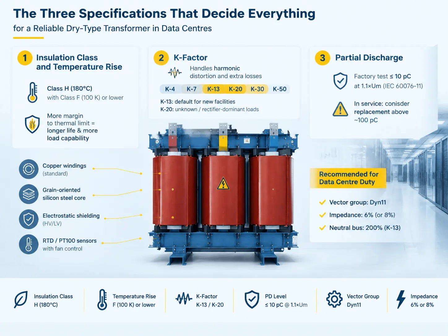
K-фактор
Рейтинг K-фактора определяет уровень потерь, которые может рассеивать трансформатор, не нарушая его тепловые ограничения. Он рассчитывается в соответствии с публикацией IEEE C57.110. UL 1561 признает рейтинги нагрева K-фактора: K-1, K-4, K-9, K-13, K-20, K-30, K-40 и K-50.
Выбор зависит от фактической характеристики нагрузки:
| Профиль нагрузки | Рекомендуемый K-фактор | Типичное гармоническое содержание |
|---|---|---|
| Устаревшие серверы с 6-импульсным выпрямителем ИБП | K-13 | 30–40% THD |
| Современные серверы с 12-импульсным или IGBT выпрямителем | K-7 | 15–25% THD |
| Полностью оптимизировано с активными гармоническими фильтрами | K-4 | Ниже 10% THD |
| Смешанные нагрузки, высокая плотность, неизвестный будущий рост | K-20 | Максимальный запас |
В случае новой установки, которая не прошла гармонический анализ, K-13 считается осторожным стандартом, в то время как K-20 является обязательной величиной, когда состав нагрузки остается неизвестным. K-20 также является наиболее часто указываемым значением только для выпрямительных нагрузок.
Трансформатор с K-рейтингом включает в себя не только более тяжелое сердечник. Он использует более низкую плотность магнитного потока для гармонического потока; у него есть больший нейтраль. Трансформатор K-13 имеет нейтральный шинный провод, рассчитанный на 200% фазного рейтинга, так как тройные гармоники суммируются в нейтрали, а не взаимно уничтожаются.
Результаты в отсутствие трансформатора с K-рейтингом очевидны. Гармонические токи приводят к увеличению вихревых потерь и, следовательно, к повышению температуры и ускоренному разрушению изоляции. Гармонический поток также приводит к более высоким пиковым напряжениям, поэтому, когда все гармонические значения складываются, пиковое значение, превышающее 1.25-1.5 от номинального пика, приводит к очень высокой вероятности возникновения частичных разрядов.
Частичное разряд
Частичный разряд определяет различие между трансформатором с высоким стандартом изоляции и экономически произведенным. Согласно IEC 60076-11, уровень PD должен составлять максимум 10 pC при рабочем напряжении 1.1 раза выше номинального напряжения для экологической категории E2, которая применяется к влажным или уличным трансформаторам. Любой заводской отчет, показывающий значение PD выше 10 pC при испытательном напряжении 1.1×Um, не будет принят.
Когда дело доходит до эксплуатации, пороги изменяются. Если значение PD превышает около 100 pC при рабочем напряжении, изоляция уже повреждена достаточно, чтобы возник вопрос о замене. Поскольку прогрессия PD и тот факт, что проблема не видна снаружи, подразумевают, что следует запросить заводское испытание в момент покупки и далее контролировать.
Язык спецификации для блока питания в центре обработки данных должен быть следующим:
- Изоляция, класс H (180 °C), повышение температуры, класс F (100 K) или ниже.
- Коэффициент K, не менее K-13, или K-20 в случае выпрямителя или неизвестной нагрузки, подтвержденный заводским приемом при гармонической нагрузке.
- Векторная группа Dyn11 как стандарт входа ИБП.
- Импеданс должен составлять 6% для усиления питания или 8%, если цель состоит в снижении тока короткого замыкания.
- Электростатический экран должен быть размещен между ВН и НН катушками, чтобы избежать циркуляции гармоник нулевой последовательности.
- PD должен быть испытан на заводе в соответствии со стандартом IEC 60076-11 с подтверждением.
- Материал обмотки - медь, материал сердечника - кремнистая сталь, устройство измерения температуры может быть RTD или PT100 с системой охлаждения.
Этот набор требований производит устройство, которое не является самой дешевой ставкой и будет оставаться в эксплуатации, когда объект будет готов к следующему обновлению. Аргументация, с которой покупатель должен разобраться перед написанием спецификации, изложена в этом руководстве по ключевым метрикам и подводным камням при выборе трансформатора сухого типа для центров обработки данных, и это стоит прочитать до того, как тендерные документы будут отправлены, а не после того, как предложения вернутся.
Типы устройств сухого типа, подходящие для работы в центре обработки данных
Существует три типа конструкции, которые имеют коммерческое значение.
- Литой смоляной (эпоксидный) сухой тип. Обмотки, которые заключены в литую эпоксидную смолу. Это лучший выбор для центров обработки данных, так как он обладает наибольшими способностями против влаги и загрязнений, способностью к самозатуханию и способностью выдерживать термические циклы 2427 рабочего цикла. Более того, его проще специфицировать с использованием высокого коэффициента K.
- Вакуумно-прессованная пропитка (VPI). Обмотки, которые пропитаны лаком под вакуумом. Это дешевле, чем литая смола и механически устойчиво, но также более уязвимо к проникновению влаги в условиях влажности или близости к морю.
- Вентилируемая открытая обмотка. Наименее дорогой вариант. Редко это решение достаточно хорошее для внутренних помещений центра обработки данных.
It comes down usually to the choice of cast resin and the difference in quality of the resin, the winding design and the testing process.
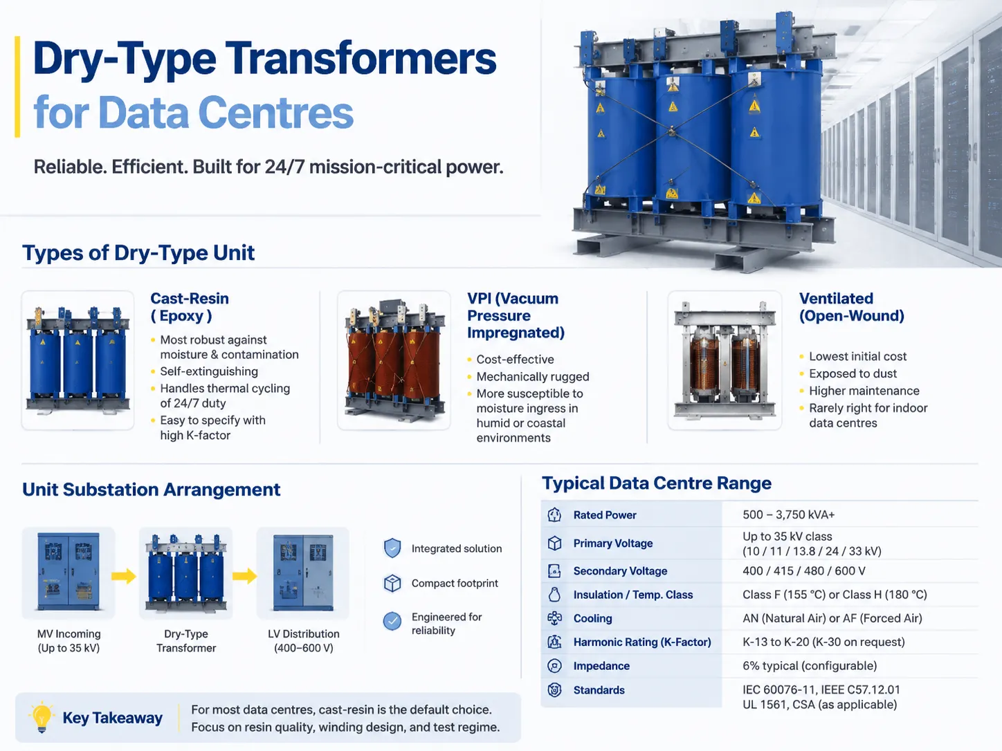
The Unit Substation Arrangement
Data centres are increasingly opting to purchase the complete power chain as one integrated, engineered product instead of acquiring the system as a series of components, such as the medium-voltage incoming section, cast resin transformer and low-voltage distribution system.
The pros of this approach include simplification of the interface and saving space. The cons are the issue of price comparison on single-source products and the fact that specifications of all parts involved become more important when welded into one component.
| Параметр | Typical data centre range |
|---|---|
| Номинальная мощность | 500–3,750 kVA, larger for hyperscale |
| Первичное напряжение | Up to 35 kV class — commonly 10, 11, 13.8, 24 or 33 kV |
| Вторичное напряжение | 400, 415, 480 or 600 V |
| Phases and frequency | Three-phase, 50 or 60 Hz |
| Insulation / temperature class | Class F (155 °C) or Class H (180 °C) |
| Охлаждение | AN natural air, or AF forced air adding roughly 33–50% capacity |
| Harmonic rating | K-13 to K-20, K-30 on request |
| Импеданс | 6% typical, configurable |
| Эффективность | DOE 2016 / EU Ecodesign / NRCan minimums |
| Стандарты | IEC 60076-11, IEEE C57.12.01, UL 1561, CSA as applicable |
Before using forced-air cooling in design, it is essential to get a proper understanding of how this process works. Forced-air cooling stage helps increase kVA output, but it does this by drawing heat away from the device and not by enhancing the insulation. In a setup with N+1 cooling configuration, this is acceptable. However, in case of using a single fan setup, it is important to understand that an AF value will not be important as soon as one of the devices fails.
This means that the list with kVA output of 500, 630, 800, 1000, 1250, 1600, 2000, and 2500 should not be treated as just a menu that one can simply pick the required value from. The selection follows the load calculation, and a cast-resin platform covering the 6–10 kV distribution ratings — the SCB-series dry-type distribution transformer range is a typical example — will usually have the right frame available in the ladder, which is a consideration when the alternative is a custom build and a longer lead time.
Redundancy and Where the Transformers Sit
Selecting the data centre transformer is closely linked to the fault-tolerant topology that it is designed to support. The rating of the transformer is determined by the topology of the setup that is either Tier III or Tier IV based on N+1 or 2N arrangement of transformers.
- N+1- A spare transformer or an ability to lose 1 transformer from a group without tripping the load. This is the usual arrangement in Tier III facilities.
- 2N- Two fully rated but independent paths of supply. This means there can be 2 transformers feeding the same group of servers, which is common in Tier IV setups.
- Block redundancy/distributed redundancy- the power supply from transformers is shared by blocks, which leads to less kVA being installed.
When calculating the transformer size, it must consider the actual IT load instead of connected load. Remember that the physically selected size of the transformer affects the PUE, because even if the transformer is working below its capacity, it still results in significant losses that the facility will have to pay for. The possibility of using a number of small transformers instead of one large unit should be carefully evaluated. This is a design decision, not merely specification.
Where a facility is configured around a defined critical infrastructure topology, the arrangement of incoming supply, transformer and distribution is the part that decides whether a single failure is survivable, and the configuration options are set out in this look at power distribution solutions for data centre and critical infrastructure.
Efficiency Regulation Is Not Optional
The efficiency requirements are obligatory in major markets and forces equipment to be different in size as well.
- USA: Development of the 2016 Department of Energy (DOE) efficiency regulation, based on NEMA TP-1, refers to the distribution transformers. In this case, more core materials and conductors will be needed to manufacture equipment that satisfies current regulations.
- European Union: Regulation EC 548/2014 defines the minimum efficiency requirements for transformers with capacity higher than 1 kVA for 50 Hz circuits. Tier 1 requirements entered into force on July 1, 2015, while Tier 2 ones came into force on July 1, 2021. Tier 2 defines maximum no-load and load losses in watts for medium-sized dry transformers and establishes minimum efficiency for the rated capacity above 3,150 kVA.
- Canada: It sets the necessary minimum efficiency requirements for similar classes of transformers.
There can be two consequences of this requirement. Firstly, the compliance transformer should be larger in size and weight compared to the non-compliance transformer of the same rating. As a result, the construction space may be exposed to some changes. Secondly, efficiency requirement and K-factor pressure are directed in the same way in relation to manufacturing, which means that the compliance transformer is heavier in terms of conductive materials.
Installation Notes Specific to Data Centre Work
- Ventilation and clearances – be sure to check with the manufacturer for minimum clearances in all directions and above as well as against NFPA 70 installation requirements. Because a cast resin transformer dissipates the losses in the room, the air handling system must be sized to handle the losses.
- Floor loading – 2000 kVA of a cast resin transformer and enclosure means heavy equipment. It is important to confirm capacity of installation location, not just that of the entrance.
- Noise rating – quiet version per NEMA ST-20 is important if the transformer is located near occupied space. This is about core clamping and low flux density design.
- Grounding and neutral – A K-rated transformer with 200 % neutral means that the conductor and bus bar need to be sized accordingly for the downstream portion of the installation. This means that choosing the transformer and undersizing the neutral bar is bad practice.
- Monitoring – install RTD or PT100 sensors to all windings and connect them to the building management system or DCIM. This is the cheapest predictive maintenance you can get in dry-type transformers.
- Termination of cables – confirm whether this is cable box, bus duct or open busbar arrangement at the place of connection and check the phase distance at that point instead of a delivery site.
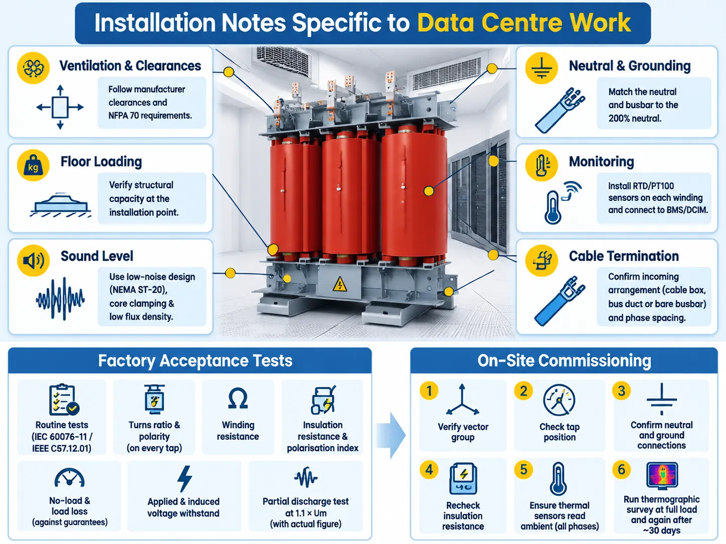
Acceptance Testing: What to Ask For
The factory acceptance test documentation must include at least the following elements: ordinary tests as required by IEC 60076-11/IEEE C57.12.01, turns ratio and polarity information for each tap, winding resistance value, insulation resistance value and polarization index value, values of no load and load losses from guaranteed numbers, results of the applied voltage withstand test and the induced voltage withstand test, result for the partial discharge test with 1.1 times Um indicated in the document as actual number.
If the transformer is K-rated, it is important to indicate some information on harmonics loading as per chosen K-factor value. Moreover, in cast resin transformers that operate in data centers, some checks must be conducted to ensure that there are no voids, cracks, or incomplete resin fill in the winding encapsulation.
At the installation site, before energizing the transformer and starting operation: confirm the vector group, tap position, neutral, and ground connection, insulation resistance as well as reading temperature in all the three phases. In addition, it is recommended to conduct a thermographic test at full load and to repeat it in a month afterward to check the ongoing temperature reading of both phases.
A structured commissioning sequence is worth following rather than improvising, and the routine tests that a dry-type unit should go through on arrival are set out in this seven-step routine test programme for dry-type transformers. Skipping the tests that are awkward to repeat after energisation is how a defective unit reaches full load before anyone knows.
Brands and How the Range Maps
The market for dry-type data center facilities can be divided into two groups: first is the construction of the entire power train and integration of the transformer into the overall design by global electrical companies, and second is the manufacturing of the transformer on specialized manufacturers’ facilities according to their specifications.
In the case of the specialized option, the key aspect would be whether the supplier has its whole production area for this purpose. Suppliers who can do cast resin dry-type projects from 6-10 kV to 35 kV with pre-tested DC solution would be working with the entire project from the same manufacturing premises instead of sourcing from different producers every time. This holds more value with phased projects than with one-time orders since the next batches of transformers produced have to work together. Subian fits this model as it is a Chinese company with dry-type and oil-immersed transformers fulfilling electrical, high-voltage and amorphous alloy transformers for international projects.
Speaking about the competitive analysis, SCB13 and its equivalents in cast resin technology is the platform on which all data center buyers compare the offers of local markets since the parameters used for each type are very similar even though the certification, methods of production may be different. That comparison is worked through in this note on how SCB13 dry-type transformers compare with international cast-resin designs, including where the differences are real and where they are documentation.
Normal price positioning works in a usual way: global brands at the top, specialist producers significantly below and the gap is becoming wider with the increase of kVA rating and the amount of customisation involved. What a buyer should not do is to compare a fully specified K-13 Class H unit with a K-1 Class F catalogue cost and thus surmise that that the cheaper product is indeed a bargain.
Часто задаваемые вопросы
Why do data centres use dry-type instead of oil-filled transformers?
Fire safety and site. Cast-resin winding does not burn and has no combustible liquids, so this equipment can be installed indoors and near the load without an oil containment facility. Maintenance is easier since there is no oil testing or gas relay or breather. This implies lower temperature tolerance that makes insulation type, temperature rise and K-factor more important for dry-type data centres than for oil-filled distribution devices.
What K-factor do I need for a data centre transformer?
K-13 is the conservative option for a facility with no harmonic study and is appropriate for legacy servers using 6-pulse UPS rectifiers with THD of 30–40%. K-20 is the correct option for loads dominated by rectifiers or loads that may grow in the future. K-7 is appropriate for new installations using 12-pulse or IGBT rectifiers with THD of 15–25%, while K-4s are used only where active harmonic filters have brought down the THD to 10% or below. Always round up to the next standard rating.
How do I size a transformer for a data centre?
Consider the actual load of the IT equipment, as well as that of the UPS design. Apply redundancy through either an N+1 or a 2N system. Air caching solutions are required only for those areas where it is redundant. An excessively loaded device will have high no-load losses, thus smaller transformers with high efficiency in partial load operation can be better than one larger device in terms of capital expenditure and efficiency measures (PUE).
What partial discharge level is acceptable?
According to the stipulations of IEC 60076-11, at Environmental Category E2, the allowed PD level is not above 10 pC at 1.1 of the rated voltage. Any factory certificate indicating a higher value must be invalidated. Under operating conditions, values above approximately 100 pC at the nominal operating voltage means the insulation condition must be considered unsatisfactory and that the insulation will have to undergo further evaluation and likely replacement.
Ссылки
- UL Solutions — UL 1561 for dry-type general purpose and power transformers, including recognised K-factor ratings
- Eaton — dry-type transformer application guidance, K-factor selection and harmonic loss explanation
- Schneider Electric — dry-type transformer specification data, temperature rise classes and efficiency compliance
- US Energy Information Administration — data centre electricity consumption and load growth analysis
- US Department of Energy — transformer efficiency standards and distribution transformer energy conservation rulemaking
- Uptime Institute — data centre tier classification, redundancy topologies and availability research
- ASHRAE — thermal guidelines and technical resources for data processing environments
- International Electrotechnical Commission — IEC 60076-11 for dry-type power transformers and IEC 60076-1 general requirements
Заключение
There are three main components that define a dry-type transformer for a data center: the insulation class that is many times higher than the temperature range that this transformer operates at; K factor indicating the level of harmonic distortion of current operating load; and partial discharge testing. If these are set up correctly together with thermal monitoring, energy efficiency, and extensive factory testing report, then the dry transformer will be in operation for twenty years without any issues. If any problems occur, it will take eight years for a failure to become evident as a fault in windings, and by this time the savings received as a result of the contract become history.