


على عكس المحولات التوزيعية التي تُستخدم في المشاريع التجارية، فإن محولات مراكز البيانات لها دور خاص: يجب أن تُوضع بالقرب من الحمل الذي تدعمه، وتعمل باستمرار بكفاءة عالية، وتتعامل مع أحمال بشكل مختلف عن أحمال الموجة الجيبية. لذا، من المستحيل استخدام المحولات الزيتية بسبب خطر الاشتعال وثلاث سمات للمحولات: الأداء التوافقي، والهامش الحراري، والتفريغ الجزئي.
باختصار: لتوصيل الطاقة لمراكز البيانات، من المناسب اختيار محول جاف من الراتنج المصبوب مع عزل حراري من الفئة H (180 درجة مئوية)، وتصنيف عامل K لا يقل عن K-13 (عادةً K-20)، وممانعة 6%، ومجموعة متجه Dyn11 لدخل UPS، وأقل من أو يساوي 10 pC لقيمة اختبار التفريغ الجزئي عند 1.1× الجهد المقنن، ووفقًا لمعايير DOE 2016 أو EU Ecodesign Tier 2 من حيث الأداء. تتراوح تصنيفات الطاقة النموذجية لمحول مراكز البيانات بين 500 kVA و 3,750 kVA عند 10 kV و 35 kV، على التوالي.
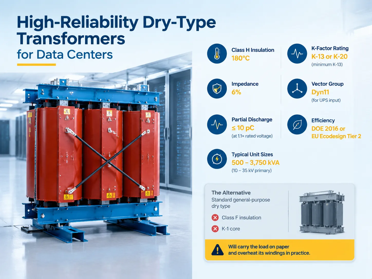
لماذا تستخدم مراكز البيانات النوع الجاف في المقام الأول
العامل الأساسي هو سلامة النظام من الحرائق. يمكن أن تنطفئ لفات الراتنج المصبوب ذاتيًا ولا تحتوي على أي سوائل قابلة للاشتعال، لذا يمكن وضع المحول في المبنى بالقرب من الحمل الذي سيتم خدمته. وبالتالي، لا حاجة لوجود حفرة زيت، أو جدار أمان، أو حجرة خاصة بخصائص مقاومة للحريق جيدة. يتم وضع المحول في جوار معدات تكنولوجيا المعلومات في مراكز البيانات المشتركة أو المؤسسية حيث كل متر مربع من المساحة البيضاء له قيمة؛ لذلك، يتم تقليل مسافة سلك الجهد المنخفض.
العامل الدافع التالي هو متطلبات الصيانة. لا حاجة لمراقبة مستوى الزيت، أو مرحل الغاز، أو تجفيف جهاز التنفس. بدلاً من ذلك، يجب مراقبة التفريغ الجزئي ودرجة الحرارة فقط، وهو أمر بسيط مقارنةً بعملية كيمياء السوائل.
من ناحية أخرى، لا تتحمل المحولات الجافة الحرارة بشكل جيد. يتحرك الزيت ويساعد في إزالة الحرارة بعيدًا عن اللفات، بينما لا يفعل الراتنج ذلك. وبالتالي، تصبح فئة العزل، وزيادة درجة الحرارة، والتوافقيات أكثر أهمية بكثير في حالة المحولات الجافة حيث أن المسافة بين التشغيل العادي وتلف العزل أصغر بكثير.
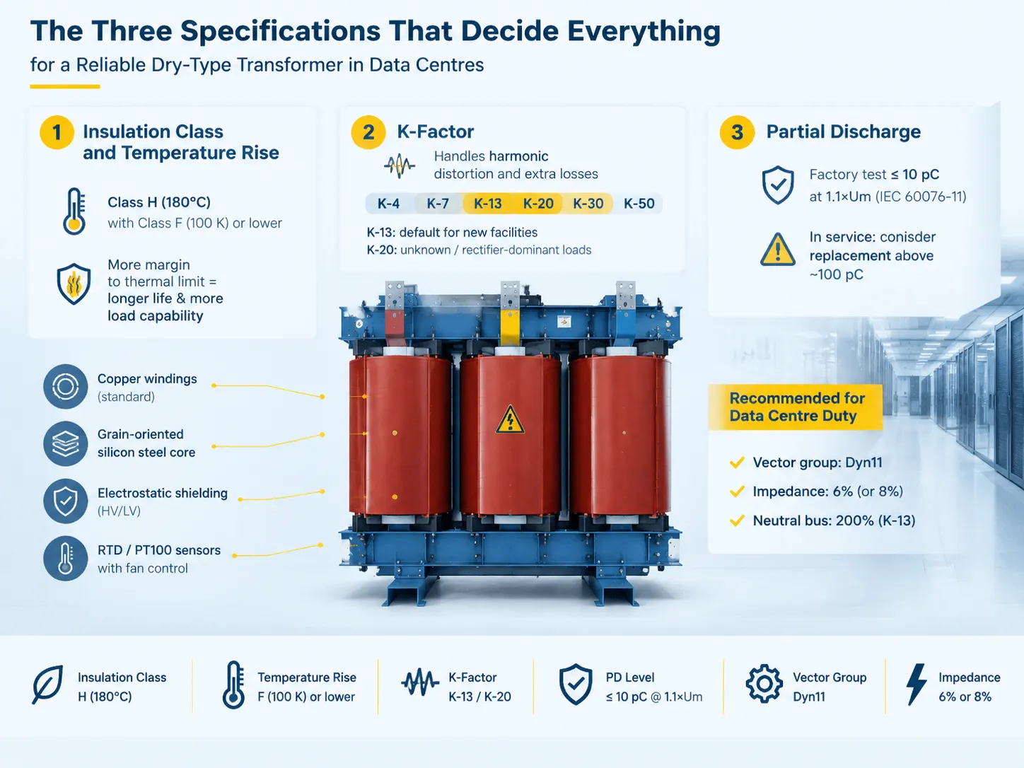
المواصفات الثلاثة التي تحدد كل شيء
فئة العزل وزيادة درجة الحرارة
وفقًا لمعيار ANSI/IEEE C57.12.01، يتم تصنيف المحولات الجافة عادةً إما بزيادة درجة حرارة 80 أو 115 أو 150 K عند بيئة 40 درجة مئوية لنظام العزل 220 درجة مئوية. وبالتالي، فإن زيادة درجة حرارة أقل على نفس المعدات تضمن هامشًا أكبر للقيود الحرارية، مما يزيد من عمر العزل ويخلق قدرة على التحميل الزائد.
من وجهة نظر IEC، تتوافق فئات العزل مع الفئة F (155 درجة مئوية) والفئة H (180 درجة مئوية) بالإضافة إلى ارتفاع درجة حرارة الفئة B (80 درجة مئوية) التي لوحظت أثناء الحمل المقنن. لاستخدام مراكز البيانات، من الممارسات القياسية أن تتطلب عزل من الفئة H مع ارتفاع درجة حرارة من الفئة B أو الفئة F، مما يعني أن العزل يتميز بدرجة حرارة أعلى بكثير من تلك التي لوحظت أثناء تشغيل المحول، مما يترك مكانًا لتبديد الخسائر التوافقية الناتجة عن المعدات أثناء التشغيل.
هذه هي المواصفة التي يتم تعديلها غالبًا في العطاء لتقليل قيمتها والمنتج الذي يفشل بعد ثماني سنوات.
عامل K
تحدد تصنيف عامل K مستوى الخسارة التي يمكن أن يتم تبديدها بواسطة المحول دون انتهاك حدوده الحرارية. يتم حسابه وفقًا لمنشور IEEE C57.110. تعترف UL 1561 بتصنيفات تسخين عامل K، K-1، K-4، K-9، K-13، K-20، K-30، K-40، وK-50.
يعتمد الاختيار على الخصائص الفعلية للحمل:
| ملف الحمل | عامل K الموصى به | محتوى التوافقيات النموذجي |
|---|---|---|
| الخوادم القديمة مع مقوم UPS ذو 6 نبضات | ك-13 | 30–40% THD |
| الخوادم الحديثة مع مقوم ذو 12 نبضة أو IGBT | ك-7 | 15–25% THD |
| مُحسَّن بالكامل مع فلاتر توافقيات نشطة | ك-4 | أقل من 10% THD |
| أحمال مختلطة، كثافة عالية، نمو مستقبلي غير معروف | ك-20 | الحد الأقصى |
في حالة تركيب جديد لم يخضع لتحليل توافقي، يعتبر K-13 هو المعيار الحذر، بينما K-20 هو الرقم الإلزامي حيث يبقى مزيج الحمل غير معروف. K-20 هو أيضًا القيمة الأكثر شيوعًا المحددة لأحمال المقوم فقط.
يتكون المحول المصنف K من أكثر من مجرد قلب أثقل. يستخدم كثافة تدفق أقل لتدفق التوافقيات؛ لديه حيادي أكبر. يحتوي محول K-13 على حافلة حيادية مصنفة لـ 200% من تصنيف الطور حيث يتم جمع التوافقيات الثلاثية في الحيادي بدلاً من إلغاء بعضها البعض.
النتائج في غياب محول مصنف K واضحة. تؤدي التيارات التوافقية إلى زيادة خسائر الدوامة، وبالتالي، ارتفاع درجات الحرارة وتسريع تدهور العزل. يؤدي تدفق التوافقيات أيضًا إلى ارتفاع الفولتية القصوى، لذا عندما تتجمع جميع قيم التوافقيات، فإن القيمة القصوى التي تزيد عن 1.25-1.5 من الذروة المقننة تؤدي إلى احتمال مرتفع جدًا لحدوث تفريغات جزئية.
التفريغ الجزئي
يحدد التفريغ الجزئي للتفريق بين محول عالي الجودة مصنوع من الراتنج ومحول مُصنع اقتصاديًا. وفقًا لـ IEC 60076-11، يجب أن تكون نسبة PD بحد أقصى 10 pC مع جهد تشغيل يبلغ 1.1 مرة من الجهد المقنن لفئة البيئة E2 التي تنطبق على المحولات الرطبة أو الخارجية. أي تقرير مصنع يظهر قراءة PD أكبر من 10 pC عند جهد اختبار 1.1×Um لن يتم قبوله.
عندما يتعلق الأمر بالتشغيل، تتغير العتبات. إذا تجاوزت قيمة PD حوالي 100 pC عند جهد التشغيل، فإن العزل قد تضرر بما فيه الكفاية ليثير تساؤل الاستبدال. لأن تقدم PD وحقيقة أن المشكلة غير مرئية من الخارج تعني أنه يجب طلب اختبار المصنع في لحظة الشراء ومراقبتها لاحقًا.
يجب أن تكون لغة المواصفات لوحدة الطاقة في مركز البيانات كما يلي:
- العزل، الفئة H (180 درجة مئوية)، ارتفاع درجة الحرارة، الفئة F (100 كلفن) أو أقل.
- عامل K، على الأقل K-13، أو K-20 في حالة الموحد أو الحمل غير المعروف، مؤكد من خلال قبول المصنع عند الحمل التوافقي.
- مجموعة المتجهات Dyn11 كمعيار إدخال UPS.
- يجب أن تكون المقاومة 6% لتقوية إمدادات الطاقة أو 8% إذا كان الهدف هو تقليل تيار القصر.
- يجب وضع درع كهربائي بين لفائف HV و LV لتجنب دوران التوافقيات ذات التسلسل الصفري.
- يجب اختبار PD في المصنع وفقًا لمعيار IEC 60076-11، مع تأكيد.
- مادة اللف هي النحاس، ومادة القلب هي الصلب السيليكوني، وجهاز قياس درجة الحرارة يمكن أن يكون RTD أو PT100 مع نظام تبريد.
مجموعة المتطلبات هذه تنتج وحدة ليست الأرخص، وهي التي ستظل في الخدمة عندما يحين موعد تجديد المنشأة. المنطق الذي يحتاج المشتري إلى التفكير فيه قبل كتابة المواصفات موضح في هذا الدليل لـ المقاييس الرئيسية والفخاخ عند اختيار محول جاف لمراكز البيانات, ، ومن الجدير قراءته قبل إرسال وثائق المناقصة بدلاً من بعد عودة العروض.
أنواع الوحدات الجافة التي تناسب واجب مركز البيانات
هناك ثلاثة أنواع من البناء ذات صلة تجاريًا.
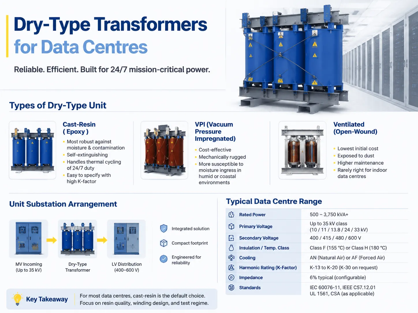
- نوع جاف من الراتنج المصبوب (الإيبوكسي). لفات محاطة براتنج الإيبوكسي المصبوب. إنه الخيار الأفضل لمراكز البيانات لأنه يمتلك أكبر ثروة من القدرة على مقاومة الرطوبة والتلوث، وقدرة على الإطفاء الذاتي وقدرة على تحمل الدورة الحرارية لدورة العمل 2427. علاوة على ذلك، من الأسهل تحديده باستخدام عامل K مرتفع.
- مغلف تحت ضغط الفراغ (VPI). لفات مغلفة بالورنيش تحت الفراغ. هذا أقل تكلفة من الراتنج المصبوب ومقاوم ميكانيكيًا ولكنه أيضًا أكثر عرضة لاختراق الرطوبة في ظروف الرطوبة أو القرب من البحر.
- مفتوح التهوية. الأقل تكلفة. نادرًا ما يكون هذا القرار جيدًا بما يكفي لداخل مركز البيانات.
It comes down usually to the choice of cast resin and the difference in quality of the resin, the winding design and the testing process.
The Unit Substation Arrangement
Data centres are increasingly opting to purchase the complete power chain as one integrated, engineered product instead of acquiring the system as a series of components, such as the medium-voltage incoming section, cast resin transformer and low-voltage distribution system.
The pros of this approach include simplification of the interface and saving space. The cons are the issue of price comparison on single-source products and the fact that specifications of all parts involved become more important when welded into one component.
| المعامل | Typical data centre range |
|---|---|
| القدرة المقدرة | 500–3,750 kVA, larger for hyperscale |
| الجهد الأولي | Up to 35 kV class — commonly 10, 11, 13.8, 24 or 33 kV |
| الجهد الثانوي | 400, 415, 480 or 600 V |
| Phases and frequency | Three-phase, 50 or 60 Hz |
| Insulation / temperature class | Class F (155 °C) or Class H (180 °C) |
| التبريد | AN natural air, or AF forced air adding roughly 33–50% capacity |
| Harmonic rating | K-13 to K-20, K-30 on request |
| المقاومة | 6% typical, configurable |
| الكفاءة | DOE 2016 / EU Ecodesign / NRCan minimums |
| المعايير | IEC 60076-11, IEEE C57.12.01, UL 1561, CSA as applicable |
Before using forced-air cooling in design, it is essential to get a proper understanding of how this process works. Forced-air cooling stage helps increase kVA output, but it does this by drawing heat away from the device and not by enhancing the insulation. In a setup with N+1 cooling configuration, this is acceptable. However, in case of using a single fan setup, it is important to understand that an AF value will not be important as soon as one of the devices fails.
This means that the list with kVA output of 500, 630, 800, 1000, 1250, 1600, 2000, and 2500 should not be treated as just a menu that one can simply pick the required value from. The selection follows the load calculation, and a cast-resin platform covering the 6–10 kV distribution ratings — the SCB-series dry-type distribution transformer range is a typical example — will usually have the right frame available in the ladder, which is a consideration when the alternative is a custom build and a longer lead time.
Redundancy and Where the Transformers Sit
Selecting the data centre transformer is closely linked to the fault-tolerant topology that it is designed to support. The rating of the transformer is determined by the topology of the setup that is either Tier III or Tier IV based on N+1 or 2N arrangement of transformers.
- N+1- A spare transformer or an ability to lose 1 transformer from a group without tripping the load. This is the usual arrangement in Tier III facilities.
- 2N- Two fully rated but independent paths of supply. This means there can be 2 transformers feeding the same group of servers, which is common in Tier IV setups.
- Block redundancy/distributed redundancy- the power supply from transformers is shared by blocks, which leads to less kVA being installed.
When calculating the transformer size, it must consider the actual IT load instead of connected load. Remember that the physically selected size of the transformer affects the PUE, because even if the transformer is working below its capacity, it still results in significant losses that the facility will have to pay for. The possibility of using a number of small transformers instead of one large unit should be carefully evaluated. This is a design decision, not merely specification.
Where a facility is configured around a defined critical infrastructure topology, the arrangement of incoming supply, transformer and distribution is the part that decides whether a single failure is survivable, and the configuration options are set out in this look at power distribution solutions for data centre and critical infrastructure.
Efficiency Regulation Is Not Optional
The efficiency requirements are obligatory in major markets and forces equipment to be different in size as well.
- USA: Development of the 2016 Department of Energy (DOE) efficiency regulation, based on NEMA TP-1, refers to the distribution transformers. In this case, more core materials and conductors will be needed to manufacture equipment that satisfies current regulations.
- European Union: Regulation EC 548/2014 defines the minimum efficiency requirements for transformers with capacity higher than 1 kVA for 50 Hz circuits. Tier 1 requirements entered into force on July 1, 2015, while Tier 2 ones came into force on July 1, 2021. Tier 2 defines maximum no-load and load losses in watts for medium-sized dry transformers and establishes minimum efficiency for the rated capacity above 3,150 kVA.
- Canada: It sets the necessary minimum efficiency requirements for similar classes of transformers.
There can be two consequences of this requirement. Firstly, the compliance transformer should be larger in size and weight compared to the non-compliance transformer of the same rating. As a result, the construction space may be exposed to some changes. Secondly, efficiency requirement and K-factor pressure are directed in the same way in relation to manufacturing, which means that the compliance transformer is heavier in terms of conductive materials.
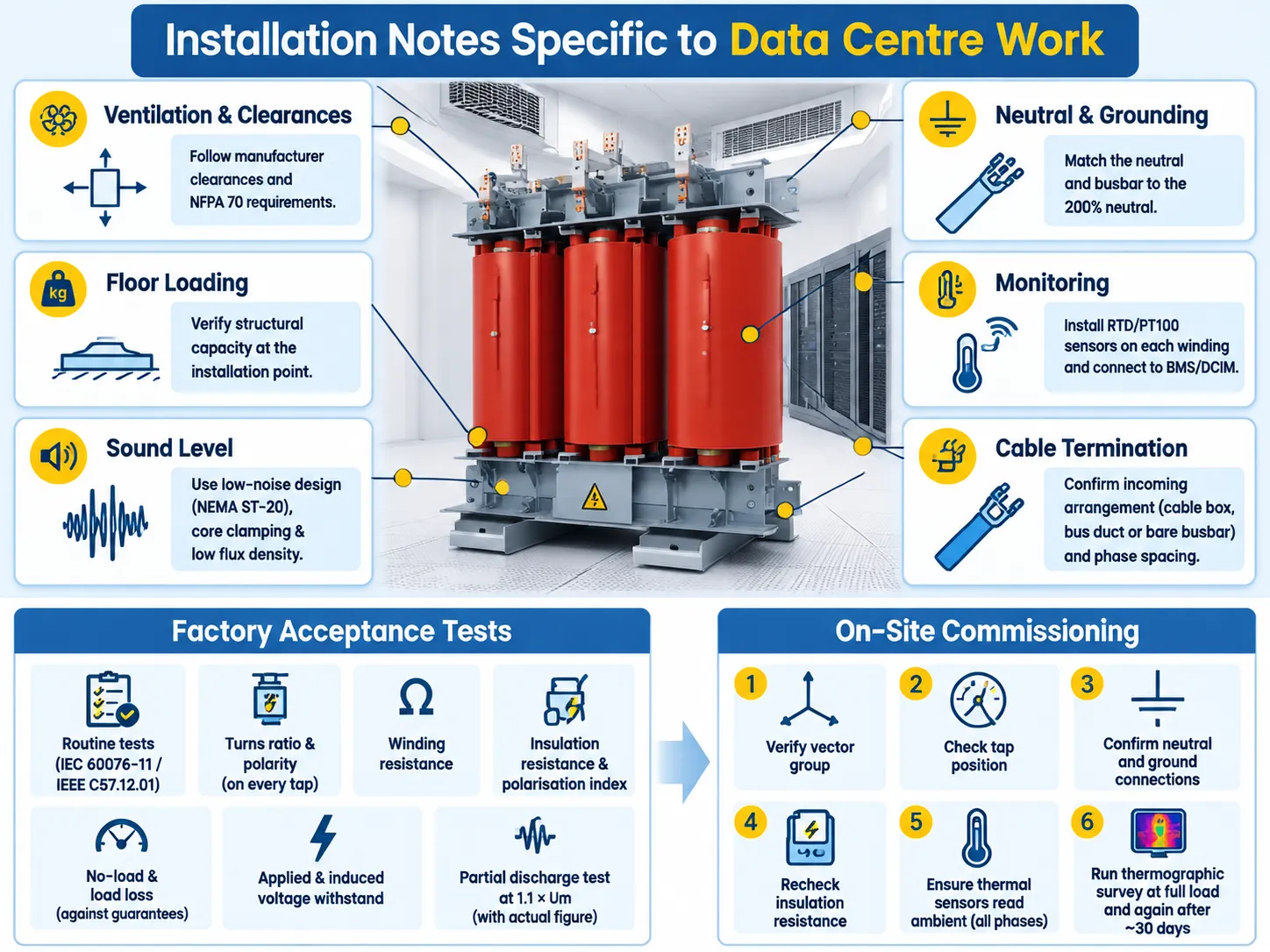
Installation Notes Specific to Data Centre Work
- Ventilation and clearances – be sure to check with the manufacturer for minimum clearances in all directions and above as well as against NFPA 70 installation requirements. Because a cast resin transformer dissipates the losses in the room, the air handling system must be sized to handle the losses.
- Floor loading – 2000 kVA of a cast resin transformer and enclosure means heavy equipment. It is important to confirm capacity of installation location, not just that of the entrance.
- Noise rating – quiet version per NEMA ST-20 is important if the transformer is located near occupied space. This is about core clamping and low flux density design.
- Grounding and neutral – A K-rated transformer with 200 % neutral means that the conductor and bus bar need to be sized accordingly for the downstream portion of the installation. This means that choosing the transformer and undersizing the neutral bar is bad practice.
- Monitoring – install RTD or PT100 sensors to all windings and connect them to the building management system or DCIM. This is the cheapest predictive maintenance you can get in dry-type transformers.
- Termination of cables – confirm whether this is cable box, bus duct or open busbar arrangement at the place of connection and check the phase distance at that point instead of a delivery site.
Acceptance Testing: What to Ask For
The factory acceptance test documentation must include at least the following elements: ordinary tests as required by IEC 60076-11/IEEE C57.12.01, turns ratio and polarity information for each tap, winding resistance value, insulation resistance value and polarization index value, values of no load and load losses from guaranteed numbers, results of the applied voltage withstand test and the induced voltage withstand test, result for the partial discharge test with 1.1 times Um indicated in the document as actual number.
If the transformer is K-rated, it is important to indicate some information on harmonics loading as per chosen K-factor value. Moreover, in cast resin transformers that operate in data centers, some checks must be conducted to ensure that there are no voids, cracks, or incomplete resin fill in the winding encapsulation.
At the installation site, before energizing the transformer and starting operation: confirm the vector group, tap position, neutral, and ground connection, insulation resistance as well as reading temperature in all the three phases. In addition, it is recommended to conduct a thermographic test at full load and to repeat it in a month afterward to check the ongoing temperature reading of both phases.
A structured commissioning sequence is worth following rather than improvising, and the routine tests that a dry-type unit should go through on arrival are set out in this seven-step routine test programme for dry-type transformers. Skipping the tests that are awkward to repeat after energisation is how a defective unit reaches full load before anyone knows.
Brands and How the Range Maps
The market for dry-type data center facilities can be divided into two groups: first is the construction of the entire power train and integration of the transformer into the overall design by global electrical companies, and second is the manufacturing of the transformer on specialized manufacturers’ facilities according to their specifications.
In the case of the specialized option, the key aspect would be whether the supplier has its whole production area for this purpose. Suppliers who can do cast resin dry-type projects from 6-10 kV to 35 kV with pre-tested DC solution would be working with the entire project from the same manufacturing premises instead of sourcing from different producers every time. This holds more value with phased projects than with one-time orders since the next batches of transformers produced have to work together. Subian fits this model as it is a Chinese company with dry-type and oil-immersed transformers fulfilling electrical, high-voltage and amorphous alloy transformers for international projects.
Speaking about the competitive analysis, SCB13 and its equivalents in cast resin technology is the platform on which all data center buyers compare the offers of local markets since the parameters used for each type are very similar even though the certification, methods of production may be different. That comparison is worked through in this note on how SCB13 dry-type transformers compare with international cast-resin designs, including where the differences are real and where they are documentation.
Normal price positioning works in a usual way: global brands at the top, specialist producers significantly below and the gap is becoming wider with the increase of kVA rating and the amount of customisation involved. What a buyer should not do is to compare a fully specified K-13 Class H unit with a K-1 Class F catalogue cost and thus surmise that that the cheaper product is indeed a bargain.
الأسئلة الشائعة
Why do data centres use dry-type instead of oil-filled transformers?
Fire safety and site. Cast-resin winding does not burn and has no combustible liquids, so this equipment can be installed indoors and near the load without an oil containment facility. Maintenance is easier since there is no oil testing or gas relay or breather. This implies lower temperature tolerance that makes insulation type, temperature rise and K-factor more important for dry-type data centres than for oil-filled distribution devices.
What K-factor do I need for a data centre transformer?
K-13 is the conservative option for a facility with no harmonic study and is appropriate for legacy servers using 6-pulse UPS rectifiers with THD of 30–40%. K-20 is the correct option for loads dominated by rectifiers or loads that may grow in the future. K-7 is appropriate for new installations using 12-pulse or IGBT rectifiers with THD of 15–25%, while K-4s are used only where active harmonic filters have brought down the THD to 10% or below. Always round up to the next standard rating.
How do I size a transformer for a data centre?
Consider the actual load of the IT equipment, as well as that of the UPS design. Apply redundancy through either an N+1 or a 2N system. Air caching solutions are required only for those areas where it is redundant. An excessively loaded device will have high no-load losses, thus smaller transformers with high efficiency in partial load operation can be better than one larger device in terms of capital expenditure and efficiency measures (PUE).
What partial discharge level is acceptable?
According to the stipulations of IEC 60076-11, at Environmental Category E2, the allowed PD level is not above 10 pC at 1.1 of the rated voltage. Any factory certificate indicating a higher value must be invalidated. Under operating conditions, values above approximately 100 pC at the nominal operating voltage means the insulation condition must be considered unsatisfactory and that the insulation will have to undergo further evaluation and likely replacement.
المراجع
- UL Solutions — UL 1561 for dry-type general purpose and power transformers, including recognised K-factor ratings
- Eaton — dry-type transformer application guidance, K-factor selection and harmonic loss explanation
- Schneider Electric — dry-type transformer specification data, temperature rise classes and efficiency compliance
- US Energy Information Administration — data centre electricity consumption and load growth analysis
- US Department of Energy — transformer efficiency standards and distribution transformer energy conservation rulemaking
- Uptime Institute — data centre tier classification, redundancy topologies and availability research
- ASHRAE — thermal guidelines and technical resources for data processing environments
- International Electrotechnical Commission — IEC 60076-11 for dry-type power transformers and IEC 60076-1 general requirements
الخاتمة
A dry-type transformer chosen for a data center has three key elements: the insulation category that exceeds significantly the temperature range of the transformer; the K factor that classifies the level of harmonic distortion for the operating load; and partial discharge testing. Properly adjusted insulation with a combination of thermal monitoring, energy efficiency, and extensive factory testing should ensure that the dry transformer will work for twenty years without failures. Any problems that might arise will become apparent only after eight years as a winding fault and by this time all savings provided by the contract will have been spent already.