


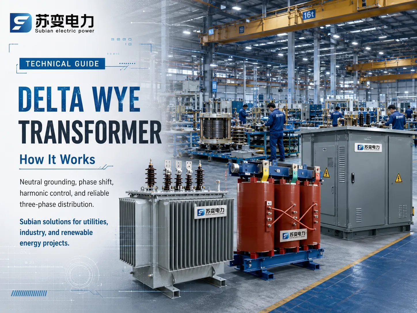
Il trasformatore Delta Wye è uno dei sistemi elettrici trifase più utilizzati nell'industria e nel commercio moderni. Gli ingegneri elettrici utilizzano il sistema Delta Wye per convertire i sistemi di distribuzione di media tensione in sistemi di distribuzione a bassa tensione e viceversa, ed è quindi molto importante avere conoscenze sui suoi processi elettromagnetici, relazioni vettoriali e dinamiche di carico per scegliere l'attrezzatura giusta per il completamento con successo del progetto. Presso Subian Electric, dispositivi di distribuzione specializzati, tra cui sistemi di trasformatori ad olio ad alta efficienza e trasformatori di tipo secco affidabili e sottostazioni montate su basamento, seguono varie norme internazionali come IEEE C57, ANSI, IEC 60076. Questo articolo apre i fondamenti del trasformatore trifase nelle connessioni Delta-Wye spiegando la sua importanza per i progetti di ingegneria elettrica in diversi paesi.
Definizioni di base: imparare a differenziare tra tipi di connessione Delta e Wye
Per capire come funziona un Trasformatore Delta-Wye, bisogna partire dai due tipi di connessione fondamentali nei sistemi AC polifase, ovvero la connessione Delta (Δ, maglia) e la connessione Wye (Y, stella).
Topologia Delta (Δ)
Nella topologia Delta, tre bobine monofase sono collegate in serie in modo da formare un anello triangolare chiuso. I terminali di fase sono quindi portati ai tre nodi di connessione. Poiché si forma una figura geometrica chiusa:
– La tensione linea-linea è uguale a quella della tensione della bobina di fase: V_line = V_phase.
– La corrente nella linea è uguale alla corrente della bobina di fase moltiplicata per √3 per un caso bilanciato: I_line = √3 * I_phase.
– La corrente di fase è in ritardo o in anticipo rispetto alla corrente di linea di un angolo elettrico di 30° a seconda della sequenza di fase.
– Se il Delta è utilizzato come un semplice circuito a tre fili, non c'è un vero punto neutro, il che significa che i carichi trifase non possono essere avviati semplicemente utilizzando l'avvolgimento Delta senza un dispositivo di messa a terra.
Topologia Wye (Y)
Nella configurazione Wye o stella, l'inizio di ciascuna bobina di fase è collegato tra loro a un nodo comune noto come punto neutro. Gli altri estremi sono quindi collegati alle tre linee o fasi. In questo modo, vengono stabilite le relazioni tra le tensioni e le correnti.
– La corrente di linea è uguale alla corrente di fase: I_line = I_phase dato che le correnti in ciascuna linea sono le stesse.
– La tensione linea-linea è uguale a √3 volte la tensione linea-neutro: V_line = √3 * V_phase (ad esempio, 480V tensione linea-linea significa 277V tensione linea-neutro o 400V tensione linea-linea significa 230V tensione linea-neutro).
– La tensione linea-linea può precedere la tensione linea-neutro di 30°.
– Il punto neutro può sia mettere a terra il Wye o può agire come un filo stabilendo un sistema trifase a quattro fili affidabile in grado di fornire sia carichi monofase che trifase.
Come funziona un Trasformatore Delta Wye: Principi elettromagnetici fondamentali
Il trasformatore trifase funziona secondo il principio della legge di induzione elettromagnetica di Faraday e della legge circuitale di Ampere. Ogni volta che l’alimentazione trifase a media tensione è collegata ai terminali primari Delta (H1, H2, H3), una corrente alternata scorre attraverso gli avvolgimenti primari.
Queste variazioni di corrente producono un campo magnetico all’interno del nucleo costituito da acciaio al silicio orientato a grani ad alta permeabilità o metallo amorfo. Poiché i circuiti primari sono disposti in configurazione Delta che si estende su due conduttori di linea in ingresso, essi sperimentano l’intera alimentazione primaria della corrente.
Il campo magnetico prodotto nel nucleo di ogni spira è direttamente collegato all’avvolgimento posto sulla stessa spira. Secondo il rapporto di spire del trasformatore (N1/N2), le tensioni negli avvolgimenti secondari saranno generate in proporzione a quelle negli avvolgimenti primari. In un trasformatore Delta Wye, tutti gli avvolgimenti secondari sono collegati alla barra neutra e la tensione nei tre avvolgimenti secondari è la tensione attraverso i passacavi (X1, X2 e X3).
Trasformazione di Tensione e Corrente Passo dopo Passo
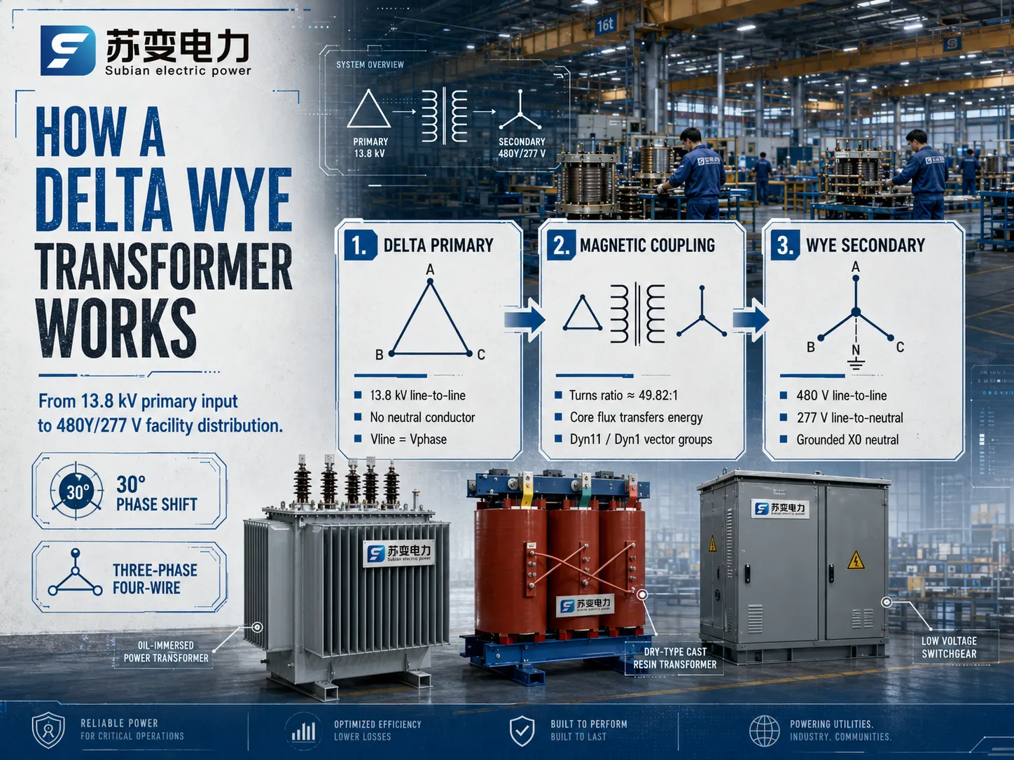
Per misurare il flusso di potenza di un trasformatore Delta Wye riduttore, prenderemo quindi un trasformatore industriale prodotto da Subian Electric, che trasforma la tensione di un alimentatore primario da 13.800V in 480Y/277V utilizzata da un impianto:
Passaggi per la fase primaria: In un sistema primario, un servizio da 13,8 kV trasmette conduttori trifase e non ha alcun conduttore neutro. Quindi, è stato collegato linea-linea senza alcun neutro, il che significa che è stato classificato per 13.800V.
Accoppiamento Elettromagnetico: Ora deve essere effettuato il calcolo del rapporto di spire in base alla tensione di fase. Un avvolgimento secondario fornirà un’uscita di 277V (480V / √3). Quindi, il rapporto di spire fisico effettivo del trasformatore dovrebbe essere 13.800V : 277V, il che significa che il rapporto di spire è circa 49,82:1.
Infine, Creazione Secondaria: Quando tre bobine con un’uscita di 277V sono collegate in formazione Wye, due fasi attive produrranno una tensione di 480V.
Gruppi Vettoriali, Spostamento Angolare e Sfasamento di Fase
Quando un trasformatore viene commutato da configurazione Delta a Wye, si verifica uno spostamento geometrico nei vettori di tensione. Lo sfasamento angolare di fase che si verifica nell’ingegneria elettrica multivariabile è rappresentato nel sistema di notazione orologio secondo le specifiche IEC 60076 e IEEE.
Il Gruppo Vettoriale Dyn11
Tra i diversi gruppi vettoriali specificati a livello internazionale, il gruppo vettoriale Dyn11 è il più utilizzato.
D: L’avvolgimento primario ad alta tensione è collegato in configurazione delta.
y: L’avvolgimento secondario a bassa tensione è collegato in configurazione wye.
n: Il filo neutro è portato all’esterno per consentire un facile collegamento.
11: Il vettore linea-neutro a bassa tensione precede il vettore linea-linea ad alta tensione di un angolo di 30 gradi (che corrisponde alle 11 in punto su un orologio dove un’ora equivale a 30 gradi).
Il Gruppo Vettoriale Dyn1
Al contrario, le installazioni in alcune reti regionali del Nord America utilizzano il gruppo vettoriale Dyn1. Il metodo qui è che il vettore a bassa tensione è in ritardo rispetto al vettore ad alta tensione di un angolo di 30 gradi (che corrisponde all'1). Anche se entrambi i tipi di trasformatore sono identici in termini di trasformazione di potenza e attenuazione armonica, diverse configurazioni vettoriali (ad es. Dyn11 vs. Dyn1) non possono essere messe in parallelo. Quando trasformatori con diverse tecniche di spostamento di fase vengono messi in parallelo, si produce un significativo cortocircuito fase-fase a causa dell'aumento della differenza di tensione angolare.
Vantaggi ingegneristici chiave della configurazione Delta Wye
I progettisti di sistemi di potenza scelgono il trasformatore Delta Wye rispetto a disposizioni alternative (come Wye-Wye, Delta-Delta o Wye-Delta) per diversi motivi critici di prestazione elettrica.
| Configurazione del trasformatore | Disponibilità del neutro | Comportamento del terzo armonico | Tolleranza al carico sbilanciato | Applicazioni comuni |
|---|---|---|---|---|
| Delta – Wye (Δ – Y) | Sì (Secondario X0) | Intrappolato nel loop Delta primario | Eccellente (Il neutro gestisce lo sbilanciamento) | Distribuzione industriale, strutture commerciali, sottostazioni montate su basamento |
| Wye – Wye (Y – Y) | Sì (Entrambi i lati) | Può causare il galleggiamento del neutro a meno che non esista un delta terziario | Povero senza neutro stabilizzato | Interconnessioni di trasmissione ad alta tensione |
| Delta – Delta (Δ – Δ) | No (Richiede banca di messa a terra) | Intrappolato in entrambi i circuiti Delta | Moderato (Può funzionare in delta aperto se una fase fallisce) | Carichi di motori industriali pesanti, impianti delta isolati |
| Wye – Delta (Y – Δ) | Sì (Solo primario) | Intrappolato nel circuito Delta secondario | Moderato | Trasformatori elevatori di generatore (GSU) |
Eliminazione delle tensioni armoniche di terzo ordine
I carichi non lineari come i variatori di frequenza (VFD), i raddrizzatori, le alimentazioni per computer e l'illuminazione a LED assorbono correnti ricche di armoniche triplen, prevalentemente la 3ª armonica (180 Hz in un sistema a 60 Hz, 150 Hz in un sistema a 50 Hz). Le correnti armoniche di terzo ordine sono componenti a sequenza zero, il che significa che sono perfettamente in fase tra loro su tutte e tre le fasi elettriche.
In un trasformatore Delta Wye, tutte le correnti armoniche a sequenza zero generate sul lato secondario si riflettono nell'avvolgimento primario. Poiché l'avvolgimento primario forma un circuito Delta chiuso, queste correnti armoniche di terzo ordine in fase circolano in modo innocuo all'interno del circuito triangolare e non possono sfuggire sulla linea di trasmissione primaria. Questa efficace soppressione della terza armonica previene le interferenze nelle telecomunicazioni a monte, riduce la distorsione di tensione a livello di sistema e protegge l'attrezzatura dell'utility a monte da surriscaldamenti severi.
Gestione robusta dei carichi sbilanciati
Negli impianti commerciali e residenziali, i carichi monofase sono raramente distribuiti con assoluta simmetria matematica tra le tre fasi. Quando si verifica una condizione sbilanciata sul lato Wye secondario, una significativa corrente di ritorno fluisce attraverso il filo neutro (X0). Poiché il neutro secondario è fisicamente messo a terra, questa capacità di gestione del carico sbilanciato garantisce che le tensioni fase-neutro rimangano stabili senza causare la distorsione di tensione di fase nota come “deriva del punto neutro” o “neutro flottante”, che affligge frequentemente i trasformatori Wye-Wye non messi a terra.
Fornitura simultanea di tensione duale
La connessione Wye secondaria fornisce due distinti livelli di tensione di utilizzo da un'unità singola:
- Tensione Linea-Linea: Alimenta grandi carichi induttivi trifase come chiller, pompe, utensili da macchina e linee di processo di produzione.
- Tensione Linea-Neutro: Alimenta carichi monofase degli edifici, prese generali per uffici, elettronica di automazione degli edifici e apparecchi di illuminazione architettonica.
Questa flessibilità a doppia tensione semplifica drasticamente l'architettura degli quadri elettrici dell'impianto e riduce la spesa iniziale in capitale per trasformatori di abbassamento supplementari.
Saturazione del nucleo e controllo dell'inrush
Il design del nucleo magnetico di un'unità trifase deve gestire condizioni di flusso asimmetrico durante l'energizzazione e la risoluzione dei guasti. Poiché il circuito Delta chiuso impedisce al flusso a sequenza zero di creare un riscaldamento severo del serbatoio, minimizza le correnti parassite nel contenitore in acciaio strutturale, prolungando la vita operativa dell'olio isolante o della resina dielettrica solida colata.
Soluzioni Trasformatori Elettrici Subian: Progettati per Griglie Esigenti
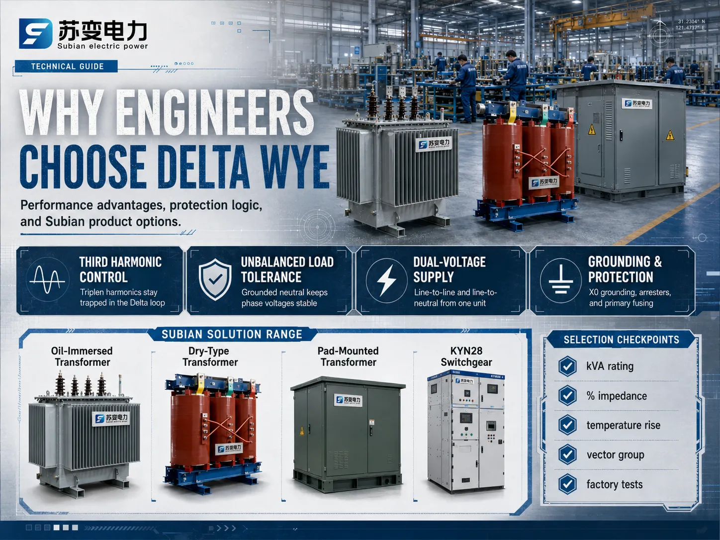
Scegliere l'attrezzatura di distribuzione giusta è importante a causa della produzione di alta qualità, della lavorazione dei metalli complicata e dei rigorosi test dielettrici coinvolti. Subian Electric si è specializzata nella creazione e produzione di tutti i tipi di sistemi di conversione dell'energia per servizi pubblici cittadini, aree commerciali, zone industriali e stazioni di produzione ecologiche.
Trasformatori di Distribuzione Immersi in Olio Subian
Per sottostazioni all'aperto, installazioni su pali di utilità e sottostazioni di impianti industriali, la trasformatore immerso nell'olio serie di Subian Electric offre una dissipazione termica superiore e una resistenza dielettrica:
- Tecnologia del Nucleo: Fabbricati con fogli di acciaio al silicio orientato a grano (CRGO) di alta qualità, laminati a freddo con giunti a miter a passo, riducendo significativamente le perdite a vuoto e abbassando i livelli di rumore acustico operativo.
- Costruzione degli Avvolgimenti: Conduttori in rame elettrolitico ad alta conducibilità o in alluminio elettrico di alta qualità con carta isolante di classe termica migliorata. Le bobine ad alta tensione sono disposte in robusti design a disco o a strati ottimizzati per resistere a sollecitazioni elettromagnetiche da cortocircuito.
- Mezzi di Raffreddamento: Olio minerale isolante ad alta dielettricità (o fluido estere naturale biodegradabile su richiesta) garantisce un rapido estrazione del calore convettivo e una lunga vita dell'isolamento in condizioni operative di carico completo continuo.
Trasformatori a Resina Epossidica di Tipo Secco Subian
In torri commerciali ad alta densità, sistemi ferroviari sotterranei, strutture mediche e sottostazioni interne dove la infiammabilità dell'olio rappresenta un rischio inaccettabile per la sicurezza, la trasformatore di tipo secco gamma di Subian Electric offre una sicurezza antincendio ottimale e resistenza all'umidità:
- Fusione a Pressione in Vuoto: Gli avvolgimenti ad alta tensione sono racchiusi in resina epossidica pura sotto alto vuoto, eliminando le microbolle d'aria e mantenendo i livelli di scarica parziale al di sotto di 10 pC.
- Classificazione Ambientale: Progettati per soddisfare gli standard internazionali di prestazione climatica (C2), ambientale (E2) e comportamento al fuoco (F1), garantendo affidabilità operativa anche in ambienti umidi, chimicamente aggressivi o polverosi.
- Bassa Manutenzione: Senza fluidi dielettrici liquidi da campionare, filtrare o sostituire, le unità in resina colata offrono costi operativi di ciclo di vita eccezionalmente bassi.
Trasformatori Compartmental Montati su Piastra Subian
Per sistemi di distribuzione elettrica sotterranea che servono centri commerciali, campus educativi, centri dati e siti di generazione di energia rinnovabile, Subian Electric produce trasformatore montato su basamento pacchetti:
- Compartimenti di Sicurezza Integrati: Involucri in acciaio zincato di spessore pesante con compartimenti bloccati a prova di manomissione che dividono la camera di terminazione del cavo a media tensione dal compartimento terminale a bassa tensione.
- Alimentazione a Loop o Radiale: Configurati per connessioni a singolo alimentazione radiale o sistemi di distribuzione a alimentazione a loop che utilizzano interruttori a carico sotto olio a due posizioni o a quattro posizioni.
- Integrazione di Energia Rinnovabile: Progettati su misura come un trasformatore elevatore di energia rinnovabile per stazioni inverter fotovoltaiche (PV) su scala di utilità e reti di raccolta di energia eolica, elevando le uscite AC degli inverter direttamente fino a 11 kV, 22 kV o 33 kV reti di raccolta.
Dimensionamento del Trasformatore e Criteri di Selezione Ingegneristica
Specificare un trasformatore Delta Wye richiede la valutazione dei parametri operativi oltre alla semplice valutazione in kVA. Gli ingegneri elettrici devono calcolare i profili di carico, la capacità di resistenza ai cortocircuiti e le condizioni ambientali per evitare l'invecchiamento termico prematuro o attivazioni inaspettate.
Calcolo della Potenza Apparente (kVA)
La valutazione totale della potenza apparente deve soddisfare la domanda continua a stato stazionario così come le condizioni di sovraccarico di picco previste. Per un sistema trifase, la capacità richiesta è determinata da:
kVA = (√3 × V_line × I_line) / 1000
Quando si dimensionano unità che alimentano alte concentrazioni di azionamenti a frequenza variabile o server di centri dati, i progettisti dovrebbero includere un fattore di derating o specificare un trasformatore con fattore K (ad es., K-4, K-13, K-20) per gestire le perdite di corrente parassita nei conduttori causate da correnti di carico armoniche.
Percentuale di Impedenza (%Z) e Calcoli di Cortocircuito
L'impedenza di perdita interna (%Z) del trasformatore stabilisce l'equilibrio tra regolazione della tensione e limitazione della corrente di cortocircuito:
- Bassa Impedenza (ad es., 3.5% a 4.5%): Migliora la regolazione della tensione durante forti oscillazioni di carico e riduce la caduta di tensione durante l'avvio di grandi motori. Tuttavia, comporta correnti di guasto prospettiche più elevate, richiedendo apparecchiature di interruzione e interruttori di circuito a capacità di interruzione più elevate (valutazioni kA).
- Alta Impedenza (ad es., 5.75% a 7%): Limita i livelli di corrente di guasto da cortocircuito, proteggendo i dispositivi di protezione e i cablaggi a valle. Il compromesso è una leggera caduta di tensione più elevata sotto carico reattivo pesante.
Aumento di Temperatura e Classe di Isolamento
Subian Electric costruisce trasformatori attraverso più classi di isolamento termico. Negli apparecchi riempiti di liquido, i progetti standard forniscono un aumento della temperatura media dell'avvolgimento di 65°C rispetto a una base ambientale media di 30°C. Nei sistemi a secco in resina colata, i materiali isolanti di Classe F (155°C) e Classe H (180°C) consentono un funzionamento continuo affidabile a 100°C o 115°C di aumenti di temperatura con riserve di sovraccarico termico integrate.
Messa a Terra Neutra e Protezione del Sistema in Installazioni Delta Wye
Il punto stella secondario (X0) di un trasformatore Delta Wye è l'ancora per la sicurezza dell'impianto e il relè di protezione. Come questo terminale neutro è riferito a terra determina il comportamento dell'intera rete di distribuzione a bassa tensione durante le condizioni di guasto a terra.
Messa a Terra Solida vs. Messa a Terra con Resistenza
- Neutro Messo a Terra Solidamente: Il terminale X0 è collegato direttamente al sistema di elettrodo di messa a terra dell'impianto con un conduttore a bassa impedenza. In caso di guasto fase-a-terra, una notevole corrente di guasto fluisce immediatamente, consentendo ai dispositivi di protezione da sovracorrente (interruttori automatici a contenitore moldato, unità di intervento elettroniche o fusibili) di isolare rapidamente il circuito guasto. Questa è una prassi standard nei servizi elettrici degli edifici commerciali.
- Messa a Terra a Bassa Resistenza (LRG): Un resistore di messa a terra neutra (NGR) è inserito tra X0 e terra, limitando tipicamente le correnti di guasto a terra tra 100A e 400A. I sistemi LRG sono prevalenti in ambienti industriali pesanti (come cartiere, raffinerie e impianti chimici) per limitare i rischi di arco elettrico e danni meccanici a grandi motori durante i guasti a terra.
- Messa a Terra ad Alta Resistenza (HRG): L'NGR limita la corrente di guasto a terra a 5A o 10A, che è insufficiente per far scattare immediatamente i dispositivi di protezione. Questo consente ai processi critici continui di rimanere alimentati mentre gli operatori localizzano la linea guasta, eliminando le fermate non programmate.
Protezione da Sovracorrente Primaria e Fulmini
Poiché l'avvolgimento Delta primario non ha un conduttore neutro, i guasti fase-a-terra sul feeder di utilità primario devono essere isolati dagli interruttori della sottostazione a monte. Per proteggere il trasformatore stesso:
- Arrestatori di Sovratensione: Gli arrestatori di sovratensione a varistore metallico-ossido (MOV) devono essere montati immediatamente accanto ai bushing primari (H1, H2, H3) per deviare in sicurezza gli impulsi di fulmine atmosferico e le sovratensioni di commutazione a terra.
- Fusibili Primari: Negli apparecchi montati su basamento, fusibili a rilevamento di corrente bay-o-net o fusibili a doppio rilevamento combinati con fusibili di backup a limitazione di corrente proteggono contro i guasti interni del trasformatore e i cortocircuiti ai terminali secondari.
Test di Fabbrica e Standard di Assicurazione Qualità
Per garantire l'integrità operativa prima della spedizione, i moderni trasformatori di potenza subiscono rigorosi test di accettazione in fabbrica (FAT) conformi agli standard internazionali:
- Misurazione della Resistenza degli Avvolgimenti: Verifica che tutte le bobine di fase abbiano resistenze bilanciate, confermando l'integrità del conduttore e le connessioni saldate solide.
- Verifica del Rapporto di Tensione e del Gruppo Vettoriale: Conferma i precisi rapporti di avvolgimento su tutte le posizioni del cambiavalute e convalida il dislocamento angolare di 30 gradi (Dyn11 o Dyn1).
- Perdita a Vuoto e Corrente di Eccitazione: Valuta le prestazioni di perdita del nucleo a tensione nominale per verificare la qualità dell'assemblaggio del nucleo e la conformità all'efficienza energetica.
- Perdita di Carico e Impedenza da Cortocircuito: Quantifica le perdite di rame (I²R) e verifica che l'impedenza interna corrisponda alle specifiche ingegneristiche.
- Test di Resistenza Dielettrica: Include test di tensione AC a frequenza di potenza a sorgente separata applicati e test di sovratensione indotta per confermare la resistenza dielettrica delle barriere di isolamento da giro a giro, da avvolgimento a avvolgimento e da avvolgimento a terra.
- Test di Resistenza all'Impulso di Fulmine: Simula transitori ad alta tensione per garantire che il sistema di isolamento resista a gravi disturbi della rete.
Domande Frequenti sui Trasformatori Delta Wye
Perché il lato primario di un trasformatore di distribuzione è solitamente Delta invece di Wye?
Collegare il primario in Delta elimina la necessità di far passare un costoso quarto conduttore neutro su lunghe distanze di trasmissione e distribuzione, risparmiando costi significativi di materiale in rame o alluminio. Inoltre, il circuito Delta intrappola naturalmente le correnti armoniche di terzo ordine a sequenza zero, impedendo loro di corrompere la rete di distribuzione dell'utility a monte.
Un trasformatore Delta Wye può essere utilizzato in modo inverso per aumentare la tensione?
Fisicamente, i trasformatori elettromagnetici sono dispositivi bidirezionali. Tuttavia, energizzare un trasformatore standard trasformatore Delta Wye in modo inverso (applicando tensione media all'avvolgimento Wye per aumentare la tensione sul lato Delta) crea complicazioni tecniche. La direzione normale del flusso di potenza determina la geometria ottimale del nucleo e la configurazione degli avvolgimenti; il flusso di potenza inverso causa un eccessivo corrente di inrush, saturazione del nucleo e problemi di neutro flottante all'estremità ricevente, a meno che non siano progettati adeguati sistemi di messa a terra, dimensionamento e relè di protezione.
Cosa causa il cambiamento di fase di 30 gradi associato alle connessioni Delta Wye?
Il cambiamento di fase di 30 gradi è un risultato geometrico e matematico del collegamento delle tensioni linea-a-linea alle tensioni linea-a-minus. Nella configurazione Delta primaria, la tensione di linea è uguale alla tensione di fase. Nella connessione Wye secondaria, la tensione di linea è calcolata in base alla differenza vettoriale tra 2 tensioni di fase separate da 120 gradi. Di conseguenza, il vettore linea-a-linea è spostato esattamente di 30 gradi elettrici rispetto al vettore fase a meno.
Cosa distingue Dyn11 da Ynd11?
Nella notazione convenzionale del gruppo vettoriale, la prima lettera maiuscola indica un avvolgimento ad alta tensione mentre la seconda lettera minuscola viene utilizzata per definire l'avvolgimento a bassa tensione. Pertanto, Dyn11 indica un avvolgimento Delta ad alta tensione con configurazione Wye a bassa tensione con un'ala neutra. Al contrario, Ynd11 indica una configurazione Wye ad alta tensione con un'ala neutra e una configurazione Delta a bassa tensione, quindi questa configurazione è solitamente utilizzata per grandi applicazioni di aumento di tensione dei generatori.
Conclusione: Costruire Reti di Distribuzione di Energia Resilienti
Il trasformatore Delta Wye rimane la base della distribuzione di energia commerciale, industriale e pubblica in tutto il mondo. Il design unico del trasformatore Delta a Wye risolve le principali sfide che affrontano i sistemi AC odierni combinando l'efficienza di trasmissione e la soppressione degli armonici dell'avvolgimento Delta primario con la flessibilità del funzionamento a doppia tensione e la stabilità a terra dell'avvolgimento Wye secondario.
La comprensione importante dei principi elettrici chiave consente l'uso di vari tipi di trasformatori, sia esso un trasformatore a olio per il funzionamento sulla linea delle utility, un trasformatore a secco per l'installazione all'interno di un edificio, o un trasformatore personalizzato montato su basamento per la raccolta di energia rinnovabile. Subian Electric offre una vasta gamma di trasformatori di potenza efficienti pronti a soddisfare i requisiti di ogni moderno sistema elettrico.