


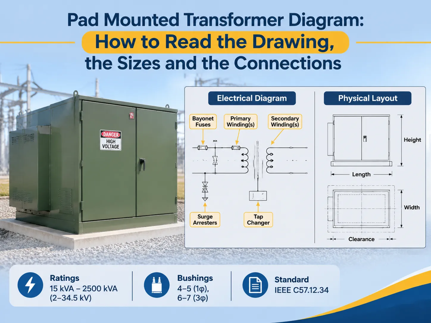
Un diagramma di trasformatore montato su basamento fornisce le informazioni che indicano se un trasformatore può essere installato, mantenuto o protetto. Il diagramma include informazioni sulle configurazioni degli avvolgimenti, la posizione dei passacavi, dispositivi di commutazione e protezione, classi di raffreddamento e dati della targhetta. Spesso, quando il trasformatore arriva in sito, verrà richiesto di fornire una copia di questo disegno all’ispettore per assistere nel processo di messa in servizio. La corretta lettura di questo documento aiuterà nella corretta installazione del trasformatore e previene problemi con i cavi di collegamento che sembrano non adattarsi ai passacavi forniti.
In breve, Un diagramma di trasformatore montato su basamento è una combinazione sia di un disegno fisico che elettrico del trasformatore. La parte elettrica mostra l’avvolgimento primario e secondario, il gruppo vettoriale, il commutatore di prese, i fusibili a baionetta, gli interruttori di commutazione sotto carico e gli scaricatori di sovratensione. L’aspetto fisico del disegno fornisce informazioni sull’ingombro dell’involucro, la posizione e l’altezza dei passacavi, i compartimenti di ingresso cavi e le distanze minime di sicurezza. Generalmente, i trasformatori monofase hanno un disegno con 4 o 5 passacavi, mentre un disegno trifase ne ha 6 o 7. Le potenze nominali variano da 15kVA a 2500kVA, con la tensione sul lato primario da 2 a 34,5kV. La norma statunitense di riferimento per involucri e dimensioni è IEEE C57.12.34.
Nelle sezioni seguenti, valuteremo i diagrammi dei trasformatori montati su basamento come un ingegnere valuta i disegni: informazioni sui componenti, come sono indicati, la differenza tra diagrammi monofase e trifase, i quattro tipi di collegamenti degli avvolgimenti, protezione e commutazione sul lato alta tensione, classi di raffreddamento, dimensioni e misure indicate nei disegni, campi dati della targhetta e le norme applicabili ai disegni. L’ultima sezione di questa guida descrive le informazioni che un potenziale acquirente di apparecchiature elettriche potrebbe voler ottenere da un preventivo di un fornitore potenziale.
I Componenti di un Diagramma di Trasformatore Montato su Basamento
Un diagramma di trasformatore montato su basamento consiste in un schema elettrico più un disegno di layout (un disegno ibrido). Poiché il layout fisico dipende dal layout elettrico, lo schema elettrico e i disegni di layout sono spesso combinati nello stesso disegno.
La parte elettrica del diagramma di trasformatore montato su basamento rappresenta tutti gli avvolgimenti collegati in un unico punto e mostra la posizione delle prese, la designazione del “gruppo vettoriale” e le posizioni di tutti i dispositivi di protezione associati a ciascun conduttore. La parte fisica del diagramma rappresenta il profilo del serbatoio, la struttura complessiva dell’armadio, la configurazione dei compartimenti alta e bassa tensione, le posizioni dei passacavi, le posizioni delle staffe di sollevamento, la posizione delle aperture di ingresso cavi e la distanza minima richiesta da recinzioni, pareti o altri trasformatori montati su basamento installati.
Oltre agli schemi elettrici e ai disegni di layout, un buon diagramma del trasformatore montato su basamento mostrerà tipicamente anche il layout della targhetta dell'apparecchiatura. Il layout della targhetta consente a un ispettore di verificare che l'unità sul basamento sia la stessa specificata dall'acquirente. La guida alle configurazioni delle sottostazioni compatte contiene ulteriori informazioni sui diversi componenti di un trasformatore montato su basamento e sul layout di un tipico set di disegni.
Quali Componenti Compongono un Trasformatore Montato su Basamento
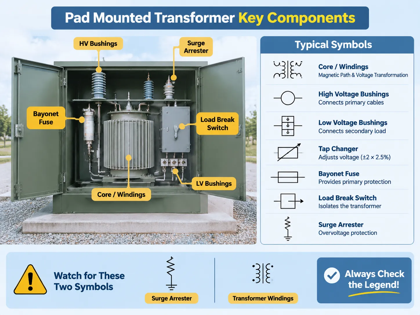
Esistono sette categorie di componenti che costituiscono praticamente tutti i trasformatori montati su basamento, e ciascuna categoria ha i propri simboli standard. I simboli possono variare leggermente da un produttore all'altro. Di seguito sono elencati i simboli tipicamente utilizzati per i trasformatori, insieme alle loro funzioni:
| componente(i) | Simbolo(i) Tipico(i) | Funzioni |
|---|---|---|
| Nucleo/Avvolgimenti | Linee parallele o anelli, punti di polarità | Percorso magnetico e trasformazione della tensione |
| Passacavi Alta Tensione | Cerchi o ovali al bordo del cabinet, numerati | Collega i cavi al lato primario del trasformatore |
| Passacavi Bassa Tensione | Morsettiere; Spesso con neutro | Collega al lato secondario del trasformatore; i passacavi a bassa tensione possono essere collegati a un carico esterno |
| Cambiatore di tap | Rettangolo con freccia O Simbolo rotante | Regolazione della tensione a vuoto (di solito ±2 × 2.5%) |
| Fusibile a baionetta | Rettangolo con linea attraverso | Fornisce protezione primaria; sostituibile dall'esterno |
| Interruttore di carico | Quadrato con freccia operativa | Isola il trasformatore dal circuito |
| Scaricatore di sovratensione | Linea a zig-zag verso terra | Protezione da sovratensioni per i passacavi primari |
Due simboli sono frequentemente fraintesi. La linea a zig-zag dello scaricatore di sovratensione crea un'interpretazione visiva errata della rappresentazione semplificata degli avvolgimenti del trasformatore. Confondere questi due simboli altera la comprensione dello schema di protezione del trasformatore da parte del lettore. I punti di polarità sugli avvolgimenti forniscono informazioni precise (piccole, ma definitive): forniscono evidenza della relazione di fase all'interno degli avvolgimenti del trasformatore. Un disegno letto senza questi due punti fornisce un raggruppamento vettoriale che non corrisponde a quello indicato sulla targhetta del trasformatore.
Per interpretare accuratamente i disegni creati dai produttori, ogni disegno deve includere una legenda. Poiché i produttori creano disegni per interruttori, fusibili e regolatori di presa, i disegni creati senza legenda forniscono al lettore un'interpretazione possibile piuttosto che un fatto assoluto.
Monofase a Trifase: Passacavi e Avvolgimenti
Contare il numero di passacavi fornisce il metodo più diretto per determinare quale diagramma ha il lettore. Un'unità monofase montata su basamento consiste in due passacavi ad alta tensione e due o tre passacavi a bassa tensione per un totale di quattro o cinque.
Le configurazioni delle boccole trifase sono solitamente installate in una di due disposizioni: tutte e tre le boccole si trovano sul lato alta tensione (HV) del trasformatore, le altre due boccole si trovano rispettivamente sul lato bassa tensione (LV) e sul neutro (presa centrale), oppure una delle due boccole può essere posizionata sul neutro per consentire l'uso di un servizio trifase a quattro fili collegato a un servizio a tre fili.
Il numero di boccole in un'unità trifase è di tre sul lato HV, più da tre a quattro sul lato LV, per un totale di sei o sette boccole. La boccola aggiuntiva è per il collegamento del neutro; quindi c'è un terminale (boccola) in più per un servizio trifase a quattro fili rispetto a un servizio a tre fili.
I kVA dell'unità trifase possono variare da 45 kVA a 2.500 kVA, con la maggior parte delle applicazioni di distribuzione che rientrano tra 75 kVA e 1.000 kVA.
Le seguenti tabelle elencano le principali somiglianze e differenze riguardanti la configurazione delle boccole e le classificazioni dei trasformatori trifase e monofase:
| Proprietà | Monofase | Trifase |
|---|---|---|
| Boccole alta tensione | 2 | 3 |
| Boccole bassa tensione | 2 o 3 | 3 o 4 |
| Gruppo vettoriale | Not applicable | Richiesto (es. Dyn11 o YNd1) |
| Valutazione tipica | 15 to 167 kVA | 45 to 2,500 kVA |
| Typical service | Residential, rural, small commercial | Commercial, industrial, subdivision |
The three-phase drawing contains additional information than what is found in a single-phase drawing; for example, it will show the zero sequence path, earthing arrangements, and the fault current data that will be required by a protection study to be made to determine what type of earth fault protection is necessary for the transformer and whether or not the transformer can be synchronised with other transformers in the substation or distribution system.
A three-phase drawing is considered incomplete unless it contains the vector group, as this is what dictates how the flow of earth fault current flows and how to utilise a three phase transformer in parallel with another three phase transformer. The distribution transformer and substation can have the same ratings both in single-phase and three-phase configurations, which makes it useful when designing a project that starts with a single transformer and develops into a bank of transformers.
How to Read the Connection Diagram
The Connection Diagram contains four types of windings, but the selection of a synchronous system connection is a matter of system design (determined by either a manufacturer or user’s intent) rather than an engineering decision.
- Delta: there are three winding sets arranged into a closed triangle with no neutral, which means the third harmonic currents from passing through the power supply, and this connection is standard for primary connecting of distribution transformers in North America. In the diagram, you can see the bushings located at each corner of the triangle.
- Wye or Star: all three sets of windings meet at one neutral point, represented as a fourth bushing, and each winding set is better suited to handle unbalanced loads; Wye configurations provide the best possible path for earth fault current to flow where there is a fault and have less impedance than delta. In the diagrams, you can see three winding sets coming together to form a common neutral point.
- Zig-Zag: each phase of the transformer is spread across two arms of the transformer core (or winding limb); connecting in a zig-zag pattern yields a low zero-sequence impedance. The purpose of this configuration is a method of solid grounding to neutral (input and output of a zig-zag) and for providing service to heavily unbalanced loads; it is used most commonly in the distribution of pad-mounted transformers and is the least frequently seen of the four configurations.
- Open Delta: with an open delta configuration, the two windings are used to deliver three-phase power (to the customer) at a reduced capacity; open-delta configurations are normally used in rural and temporary applications, where the installation of the third phase conductor would not be justified; the diagrams show only two winding sets as opposed to the typical three, and the open-delta configuration has an associated capacity derating.
One specific aspect of arithmetic that junior engineering professionals can frequently find themselves miscalculating when referencing drawings is that the delta to wye conversion requires the application of a √3 factor to the line-to-neutral relationship; thus, if this factor is omitted from the calculations, the resulting secondary voltage will end up being 58% of what it should have been. This is more often discovered at commissioning than during the design review stage since the drawing appears to be accurate, and most designers would perform their math via spreadsheet.
High Side Switching and Protection
High Side Switching and Protection –The high voltage compartment of the drawings contains the majority of their value, as this is the part that an operator actually works with. b.) Loop feed or radial feed – The loop feed unit has two sets of high voltage bushings allowing the transformer to be configured in a loop, permitting bypassing of that transformer.
The drawing indicates that both sets of bushings are present and shows where the switches are located for each. Conversely, a radial feed unit utilizes only one set of bushings. Utility companies use loop feed systems for suburban distribution because this configuration provides an opportunity to isolate a faulted transformer while still supplying power through the loop to other transformers.
Load break switch. A 4-position switch provided on the loop feed unit permitting operation as follows: 1) loop through operation; 2) transformer isolated operation; 3) one side of the loop isolated; 4) the other side of the loop isolated. The load break switch appears on the drawing as a set of contacts with an operating arrow, while the position legend next to the switch will be read by an operator before they pull the handle to operate the switch.
Bayonet fuse. Bayonet fused current limiting fuse located within a bayonet holder that allows for replacement without requiring the opening of the cabinet.
The drawing shows that the surge arresters are connected in series to the primary windings of the transformer ny , A. They are also rated against the inrush of current and fault current available from the transformer.
In lightning-prone areas, surge arresters are required per specification, and in many cases they will already be included in the utility’s design specifications for new installations.
The grounding information on the drawing shows that there is a grounding pad for the tank, a ground connection for the neutral wye, and in certain cases, a grounding bus specifically for the surge arrestors. The grounding of the transformer is critical to the successful operation of the transformer protection devices (that include surge arresters), and is often omitted on the manufacturer’s outline drawing since it pertains to the installation of the transformer and not the transformer itself.
Cooling Class Designations and How They are Shown on the Drawings
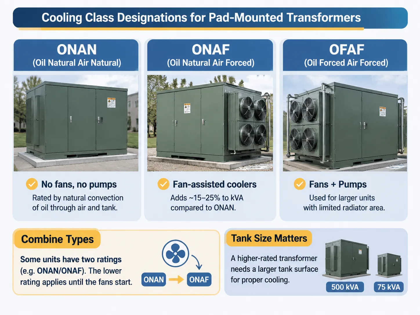
Typically, pad-mount transformers are filled with oil and cooled naturally without artificial means (fans or pumps) and are labelled according to their class on the transformer nameplate and not by any symbol on the drawings. There are four cooling class designations that cover the range of pad-mounted transformers:
- ONAN (Oil Natural Air Natural) – The transformer does not include fan or pump cooling. The rated kVA for transformer models with cooling classes ONAN would be rated at the maximum load (or combined kVA rating) based on convection of oil through both air and oil. This is the most common ratings for distribution transformers and typically includes models of transformers rated up to 2,500 kVA.
- ONAF (Oil Natural Air Forced) – The tank will have fan assisted air coolers mounted to the outside and inside of the tank. The added cooling from the fans will add between 15 and 25 percent to the rated kVA of the transformer compared to a cooling class ONAN transformer. The drawings will show the locations of the fans and the associated control system.
- OFAF (Oil Forced Air Forced) – These transformer enclosures will have both fan and pump assemblies used on larger pad mounted transformers where the available surface area for cooling (the radiators) is not sufficient.
- Combine Types.The unit may have two capacities printed on the nameplate for both ONAN/ONAF ratings; the lower capacity applies until the fans start to operate. If a purchaser reads only the higher rating, and if the fan control function fails, then the unit will overheat due to a failure to protect the motor.
As with all types of sealed pad-mounted units that do not have a radiator, smaller-rated units are predominantly designed to cool solely through the heat dissipated off of the tank surface. Hence, the physical size of the tank is equally as important as the rating of the unit. For example, a sealed unit rated at 500 kVA has a significantly larger tank surface area than a 75 kVA unit, because cooling of the transformer is dependent on thermal interactions, not electrical ones.
Site Decisions – Dimensions and Sizes by Rating
Dimensions are determined by the standard enclosure sizes specified by IEEE C57.12.34 and the manufacturers’ own tank designs. Therefore, all of the values shown below are intended only as a general reference and not as absolute specifications. Please refer to the manufacturer’s outline drawings for designing a foundation.
Typical Enclosure Footprint per Rating
- Single Phase 25 kVA – 0.9m × 0.8m; Height- 0.9m; Weight (With Oil)- 250 to 350 Kg.
- Single Phase 75 kVA – 1.2m × 0.9m; Height- 1.1m; Weight (With Oil)- 450 to 600 Kg.
- Three Phase 75 kVA – 1.3m × 1.0m; Height- 1.2m; Weight (With Oil)- 600 to 800 Kg.
- Three Phase 500 kVA – 1.6m × 1.4m; Height- 1.5m; Weight (With Oil)- 1,600 to 2,100 Kg.
- Three Phase 1,000 kVA – 2.0m × 1.6m; Height- 1.8m; Weight (With Oil)- 2,800 to 3,600 Kg.
- Three Phase 2,500 kVA – 2.6m × 2.0m; Height- 2.2m; Weight (With Oil)- 5,500 to 7,000 Kg.
These values impact three decisions on site selection.The concrete slab shall support both the total weigh plus the point loads from the lifting lugs. This is a structural question rather than a concrete one. The distance required to reach the building or the fence is determined by both the standard and the local utility and not by the dimensions of the installation. The path(s) the crane travels must support moving the unit onto a concrete slab behind the fence for a 1,000 kVA three phase unit.
Different voltage combination requirements exist as well as size. Voltage ratings for the primary are 2.4, 4.16, 7.2, 12.47, 13.2, 13.8, 24.94, 34.5 kV, while there are several common secondary connections including 120/240 single phase, 208Y/120, 480Y/277, and 600 V three phase. Although a 20 kV oil immersed distribution transformer built to IEC and 12.47 kV unit built to IEEE may look alike when photographed; they are, in every aspect that matters, two different types of equipment.
The Nameplate and What Each Field Represents
The nameplate is a summary of the drawing, with six fields determining the use or suitability of the equipment.
Rated Power: Expressed in kVA, with a separate rating for each class of cooling used; the lower value represents the continuous rating without any additional forms of cooling.
Voltage Ratio & Taps: This field contains both the primary and secondary voltage ratings along with the tap range, which is generally ±2 X 2.5% as it relates to the primary winding. Taps that are in the wrong position will create either permanent over voltage or under voltage conditions that cannot be detected by any form of protection.
Impedance: The percent of impedance, sometimes coupled with the X/R ratio.As with any electrical equipment, there are things that determine how well the equipment performs under load and during a fault condition. The amount of fault current flowing through the secondary winding determines the interrupting capacity of every downstream device.
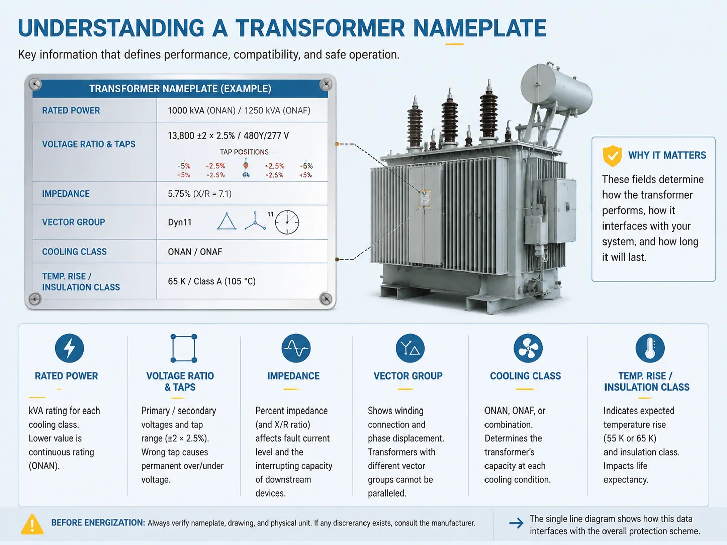
The first factor to consider is the vector group, which indicates the connection of the windings and the phase displacement in a three-phase unit. Even if two transformers are rated the same, if they have different vector groups, they cannot be connected in parallel.
The second factor is the cooling class of the transformer, whether it is ONAN, ONAF or a combination, and the ability of the transformer at each of those cooling classes.
A third factor is the temperature rise and insulation class of the transformer. For oil immersed distribution transformers, the rise is generally 55 or 65 K, and the insulation class is listed separately. Both of these figures will indicate the life expectancy of the transformer under continuous load.
Before the transformer is energized, the most effective way to verify the correctness of the manufacturer’s nameplate, drawing, and physical transformer is to do a three-way check with the nameplate, drawing, and physical unit. If there is any discrepancy between any of these documents, the manufacturer should be consulted before energization of the transformer. The single line diagram explains how the nameplate data will interface with the overall protection scheme.
The Standards Behind the Drawing
The two standard families that govern the drawings and definitions of electrical equipment are IEEE and IEC. The one you should refer to when preparing a specification for electrical equipment is the one that is specific to your equipment.
IEEE C57.12.34 is the US Standard that includes the enclosure dimensions, the heights and spacing of bushing, clearances, and the physical requirements that make a transformer interchangeable with other transformers in a utility’s inventory. IEEE C57.12.00 covers general requirements, IEEE C57.12.10 covers safety issues, and IEEE 315 establishes the graphical symbols for use in the drawings.
The IEC family (International Electrotechnical Commission) has a similar family of standards that apply internationally. IEC 60076 provides general requirements for electrical equipment (60076-1), the temperature rise of electrical equipment (60076-2), insulation level requirements (60076-3), and short circuit withstand requirements (60076-5).The standard IEC 60071 is in the area of insulation coordination—the standard specifies the value of lightning impulse levels for a particular system voltage.
The two groups are completely different. A mixed design is not fully compliant to either of the two specifications. The most common issue associated with this is with the bushing design; the bushing meets the requirements of the IEC specification but does not meet the clearances for the C57.12.34 specification. This is a physical problem that cannot be solved once the tank has been welded.
Where SUBIAN Fits into the Picture
We manufacture oil-immersed distribution transformers that range in size from 10 kVA to approximately 2500 kVA at 10, 20, 33, and 35 kV, in both pole and pad-mounted configurations. All of our units are manufactured in accordance with IEC 60076. If a project requires an IEEE-compliant unit, we will supply that type of transformer also. Most of our transformers are supplied to utility distribution systems and industrial applications, in areas where IEC equipment is used as a standard.
The package of drawings we provide at the time of quotation contains the following documents: The electrical diagram including the vector group, tap range, and outline drawing with bushing locations, clearances, and cable entry points, the transformer nameplate layout, and routine test results before shipping. The package of drawings is the primary document that the consultant uses to check the transformer design against the specifications and is the most concrete description of the substation component’s scope of purchase.
What we do not claim is a warehousing position in the United States.A utility in the United States that describes an ANSI C57.12.34 transformer with a specific enclosure configuration and bushing orientation would best be served by a manufacturer located in the United States. We will indicate this when we provide a quotation for an IEC transformer that does not conform to the specifications. If the installation accepts IEC equipment, it will also be available at a lower cost and longer lead time.
FAQ
What does the diagram of a pad mounted transformer show?
The diagram is a combination of the electrical schematic and a physical representation of the enclosure and bushings. It shows, in detail, all the electrical components, such as windings, vector groups, taps, bayonet fuses, load break switches, and surge arresters. Physically, it includes information about the enclosure footprint, bushing locations and heights, cable entry compartments, lifting points, and minimum clearances. Most drawings also replicate the nameplate layout for comparison with the order.
How many bushings can a pad mounted transformer have?
A single-phase pad mounted transformer typically has either four or five bushings. The high voltage bushings are two in number and the low voltage bushings have two or three. A three-phase pad mounted transformer will usually have either six or seven bushings, where three are high voltage and three are low voltage, plus one neutral (either high or low voltage). The fastest way to determine which drawing you are using is to count the bushings.
What is the difference between a loop feed and radial feed?
In a loop feed transformer, there are two sets of bushings for the high voltage connection and a four-position load break switch; therefore, the unit can be bypassed without causing a disruption to the loop supply circuit. A radial feed transformer only has one set of bushings and is supplied from one direction. The standard for suburban utility distribution systems is a loop feed transformer, since if a fault occurs with a loop feed unit, it can be disconnected from the unit without affecting the other circuits in the loop.
What is the correct size for the pad-mounted transformer?
Sizing of a transformer is based on the load and the diversity factor, not only on the sum of the connected nameplate ratings. Normal distribution for residential loads typically includes 25- to 100-kVA single-phase transformers, whereas commercial distribution typically includes 300 to 1,000 kVA three-phase transformers. Industrial locations usually exceed 1,000 kVA transformer sizing. The second consideration is what type of secondary voltage configuration to be implemented because once the transformer is built, the secondary voltage will remain fixed. Two of the common configurations would include 208Y/120 and 480Y/277.
References to Consult
- Hammond Power Solutions – Distribution Transformer Product Data Sheets
- SGB-SMIT Group – Technical Data and Distribution Transformer Reviews
- Ormazabal – Technical Data Medium Voltage Distribution and Substation Equipment
- Today in Energy – U.S. Department of Energy
- Distribution Transformers and Grid Equipment – Hitachi Distribution Transformers
Conclusione
A pad-mounted transformer may be read in a predetermined order of the bushings determining whether it is a single or 3-phase transformer, vector group-reading, switching, and protection on the high side and comparison of transformer dimensions vs. the pad location will aid in determining the correct size transformer and provide a description of the transformer, therefore, the nameplate is a compressed version of the information for quick reference. Having three points of reference — nameplate, drawing (schematic), and transformer on order — will help avoid surprises during commissioning.
Le due informazioni principali che influenzano la maggior parte dei progetti di costruzione includono: il gruppo vettoriale, che dovrà essere compatibile con il sistema esistente, e le dimensioni di ingombro necessarie per installare il trasformatore sulla basetta. Questi elementi appariranno nel disegno prima che l'ordine venga effettuato per evitare ritardi.