


Per molte persone, come me, l'unico modo per descrivere questi tipi di apparecchiature è “quelle rotonde”. Questi componenti rotondi sono in realtà isolatori elettrici con tubi in porcellana che supportano le linee aeree di corrente elettrica all'interno delle sottostazioni, oltre a vari componenti del trasformatore.
Risposta rapida: i tre tipi principali di componenti rotondi in una sottostazione sono boccole, isolatori e anelli corona. Le boccole sono utilizzate per far passare linee o conduttori ad alta tensione attraverso una barriera messa a terra. Gli isolatori separano e sostengono i conduttori dal terreno, fornendo anche supporto meccanico per gli isolatori che tengono i conduttori a varie altezze (tramite l'uso di una serie di isolatori). Gli anelli corona forniscono un meccanismo per ridurre lo stress elettrico sulle apparecchiature isolate. Il nome professionale per boccole, isolatori e anelli corona è rispettivamente boccole, isolatori a colonna, isolatori a sospensione e anelli corona. Quando si ordinano isolatori, è essenziale indicare chiaramente il tipo specifico nell'ordine, altrimenti risulterà ambiguo.
Questo articolo contiene descrizioni di ogni tipo di componente, le loro funzioni meccaniche ed elettriche, le ragioni per cui i componenti sono circolari, una spiegazione di come viene determinato il numero di dischi necessari e un riepilogo dell'origine dei componenti.
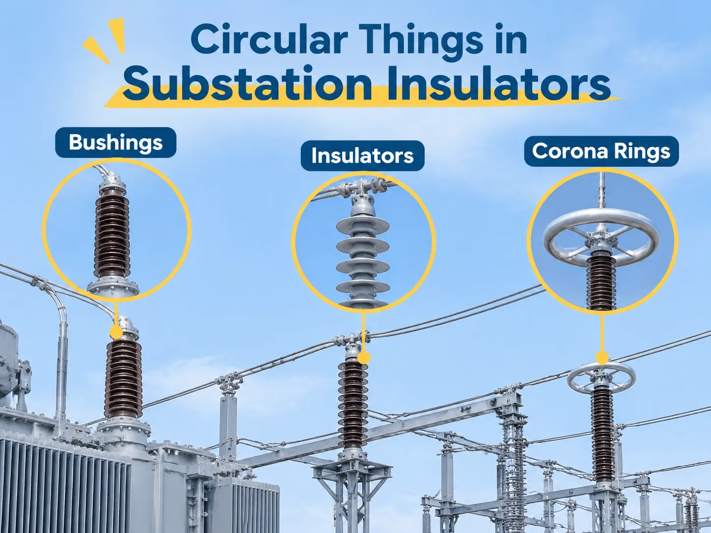
La risposta breve: tre componenti che le persone chiamano “le cose rotonde”
La boccola è un passaggio per il conduttore attraverso una barriera messa a terra. La boccola agisce come un passaggio isolato per il conduttore per mantenere intatta l'isolazione durante il passaggio attraverso la barriera messa a terra (ad esempio, trasformatore, apparecchiature di manovra, parete). La boccola non fornisce supporto e non è un separatore. La boccola agisce come una porta isolata per un filo.
L'isolatore è un supporto e separatore per il conduttore. L'isolatore a colonna sostiene il busbar per il trasformatore. L'isolatore a sospensione (dal portale al conduttore) sostiene il conduttore dal portale. In condizioni normali di funzionamento, nessuno dei due conduce corrente. Entrambi sopportano un carico meccanico mantenendo la tensione.
L'anello corona non è un supporto né un separatore. L'anello corona / di livellamento è un toro metallico avvitato attorno a un raccordo, progettato per rimodellare il campo elettrico nell'area attorno al raccordo, ed è progettato per mantenere il toro lontano dal contatto con il conduttore attivo nel punto di massima intensità del campo.
| Ciò che si vede | Componente | Conduce corrente | Sopporta carico | Posizione tipica |
|---|---|---|---|---|
| Cilindro in porcellana su un coperchio di trasformatore | boccola | sì | perdita | serbatoio del trasformatore, parete dell'apparecchiatura di manovra |
| Pila di dischi appesi in una stringa | isolatore a sospensione | perdita | sì | portale, torre di tensione |
| Colonna scanalata che sostiene un busbar | isolatore a colonna | perdita | sì | supporto busbar, base isolatore |
| Toro metallico nudo sopra un raccordo | anello corona / di livellamento | perdita | perdita | parte superiore di boccole, scaricatori di sovratensione |
Boccole: la parte rotonda attraverso cui passa il conduttore
Dalla discussione sopra, si può concludere che le boccole sono i componenti che conferiscono alle sottostazioni il loro aspetto.
In un trasformatore riempito d’olio ci sono 3 passacavi che poggiano sul coperchio del trasformatore, e ciascuno ha una colonna cava in porcellana o composito con un conduttore al centro della colonna. Lo scopo dei passacavi è mantenere il gap isolante tra il conduttore e il serbatoio del trasformatore.
Il serbatoio è messo a terra e il conduttore è a potenziale di linea (circa 72kV), con una separazione tra i due elementi di circa qualche centinaio di mm o meno. Se non ci fossero passacavi, il percorso conduttivo dal serbatoio del trasformatore al conduttore sarebbe attraverso la superficie dell’olio (flashover) o attraverso l’aria (flashover). Entrambi i percorsi tenderebbero a causare un flashover a una frazione della tensione nominale, portando a una potenziale esplosione del trasformatore.
La maggior parte dei passacavi ad alta tensione (superiori a 72kV) sono di tipo condensatore, che tipicamente consiste in un isolatore in porcellana; un nucleo di carta impregnato d’olio circondato da strati di fogli di alluminio che agiscono come condensatori successivi che riducono esponenzialmente la tensione attraverso tutto il materiale isolante tra il conduttore isolato (centro) e la flangia. Questo design fornisce molteplici capacità minori e punti di prova tan delta alla flangia, che permettono la misurazione dello stato del condensatore, oltre a fornire il punto principale per la diagnosi di possibili problemi di condizione.
Un passacavo non presenta indicazioni preliminari prima di un guasto catastrofico dovuto all’aumento del tan delta, all’incremento di umidità all’interno del nucleo di carta, o all’accumulo di pressione interna nel trasformatore. Tali guasti rappresentano uno dei pochi pericoli nell’intero ambiente della sottostazione perché il guasto catastrofico improvviso di un passacavo può causare un’esplosione, che distruggerà il serbatoio del trasformatore. I passacavi sono programmati per test, e pertanto è comune mantenere un set di ricambio. I passacavi si trovano sul trasformatore che fornisce la potenza in uscita, e un guasto di un passacavo significa che il trasformatore non sarà più in servizio indipendentemente dallo stato degli avvolgimenti. La disposizione dei componenti su un tipico trasformatore di distribuzione immerso in olio è chiaramente illustrata. Trasformatore di distribuzione immerso in olio da 20kV contiene i passacavi, il commutatore di prese e le staffe di sollevamento sul coperchio superiore, e la distanza tra i passacavi è determinata dalla classe di tensione.
Considerando la forma rotonda del passacavo, si produce un campo elettrico. Nel caso di una forma rotonda o cilindrica con lati lisci, il campo elettrico è quasi uniforme lungo tutta la sua lunghezza. Tuttavia, se il passacavo ha una sezione quadrata, il campo elettrico si concentra negli angoli, dove il raggio di curvatura è basso. L’intensità del campo elettrico negli angoli di un passacavo quadrato può essere da due a tre volte superiore al campo elettrico medio. Questa concentrazione del campo elettrico crea condizioni per il verificarsi di scariche parziali.
Le costole sul passacavo forniscono un'ulteriore considerazione progettuale. Ogni costola offre una distanza di percorso superficiale più lunga per l'umidità che deve attraversare il passacavo. In condizioni di umidità o contaminazione, la forma cilindrica liscia del passacavo ha una tensione di scarica superficiale molto più bassa rispetto al tipo costolato.
Isolatori a colonna e dischi di sospensione
Gli isolatori a colonna sono le colonne con costole sulla sommità utilizzate per supportare i conduttori, le lame di collegamento e le terminazioni dei cavi. Gli isolatori a colonna sono soggetti a una combinazione di carichi di flessione e compressione. La resistenza alla flessione, non il livello di tensione, è il valore determinante per le specifiche degli isolatori a colonna. Un isolatore a colonna elettricamente adeguato può rompersi in condizioni di cortocircuito se la capacità di carico a sbalzo non è sufficiente. Gli isolatori di sospensione sono costituiti da componenti individuali, noti come dischi, che formano una stringa. Ogni disco ha il proprio cappuccio e perno e la stringa è costruita da più dischi uniformi. Una tipica stringa da 110 kV è composta da sette a nove dischi, mentre una tipica stringa da 220 kV è composta da 13 a 16 dischi. Il numero di dischi utilizzati è determinato dalla quantità di inquinamento presente sul sito e non dalla tensione.
La classificazione della resistenza meccanica di un isolatore di sospensione è espressa come carico meccanico totale sull'isolatore di sospensione (ad esempio, 70, 120 o 160 kN) ed è basata sul tipo di lavoro svolto, mentre la classificazione della resistenza elettrica è misurata in unità di frequenza di potenza in condizioni di umidità. In termini di materiali, gli isolatori di sospensione in vetro hanno un vantaggio significativo rispetto agli isolatori di sospensione in porcellana: se un isolatore di sospensione in vetro si rompe, perde le sue proprietà isolanti ma rimane attaccato alla stringa, quindi il guasto è evidente dal terreno. Al contrario, un isolatore di sospensione in porcellana incrinato può continuare a funzionare fino alla successiva ispezione. Questa differenza nelle caratteristiche di guasto dei due materiali porta molte aziende elettriche a utilizzare isolatori di sospensione in vetro per le linee di trasmissione e isolatori di sospensione in porcellana per le sottostazioni.
Anelli corona: i cerchi metallici sopra il raccordo
Gli anelli corona sono anelli metallici situati sopra il punto di attacco (il punto di attacco si trova sopra la stringa o la connessione).
Il toro si trova sulla sommità dei passacavi ad alta tensione o degli scaricatori di sovratensione e funge da anello di livellamento. Gli anelli di livellamento non forniscono isolamento e non trasmettono carichi meccanici; gli anelli di livellamento modificano semplicemente la forma del campo elettrico; questo previene la rottura dell'aria circostante il punto di attacco.
L'area di campo elettrico massimo al passacavo è dove il conduttore elettrico esce dalla porcellana. Quando si utilizza un tubo o un anello per proteggere una linea di trasmissione dalla scarica a corona, il diametro e la dimensione del tubo aiutano ad aumentare l'area su cui si disperde la concentrazione del campo di tensione e quindi la grandezza del campo di tensione a cui si crea la corona; questo aiuta a mantenere il campo locale al di sotto del livello di innesco della corona quando si utilizza un tubo o un anello di dimensioni corrette. Inoltre, mentre la corona stessa non è dannosa, l'erosione elettrica dell'isolatore circostante causata dalla corona genera una quantità significativa di interferenze a radiofrequenza (RFI), rumore udibile e produce anche ozono che può deteriorare l'isolamento a base di gomma (ad esempio, elastomerico) e i materiali dielettrici.
Ogni palo che ha un anello o un tubo di dimensioni adeguate (il diametro dell'accessorio che circonda l'anello e l'altezza a cui il tubo è installato) ha una corrispondente classificazione di tensione. Cambiare la dimensione del tubo con una che non corrisponde alla stessa tensione (cioè, tensione più alta o più bassa) non fornisce protezione aggiuntiva e può influire negativamente sulla distribuzione dell'energia elettrica lungo il filo e può potenzialmente essere dannoso. Per questo motivo, l'anello o il tubo della classe di tensione corretta è incluso con il passacavo o l'arrestatore, piuttosto che essere un accessorio.
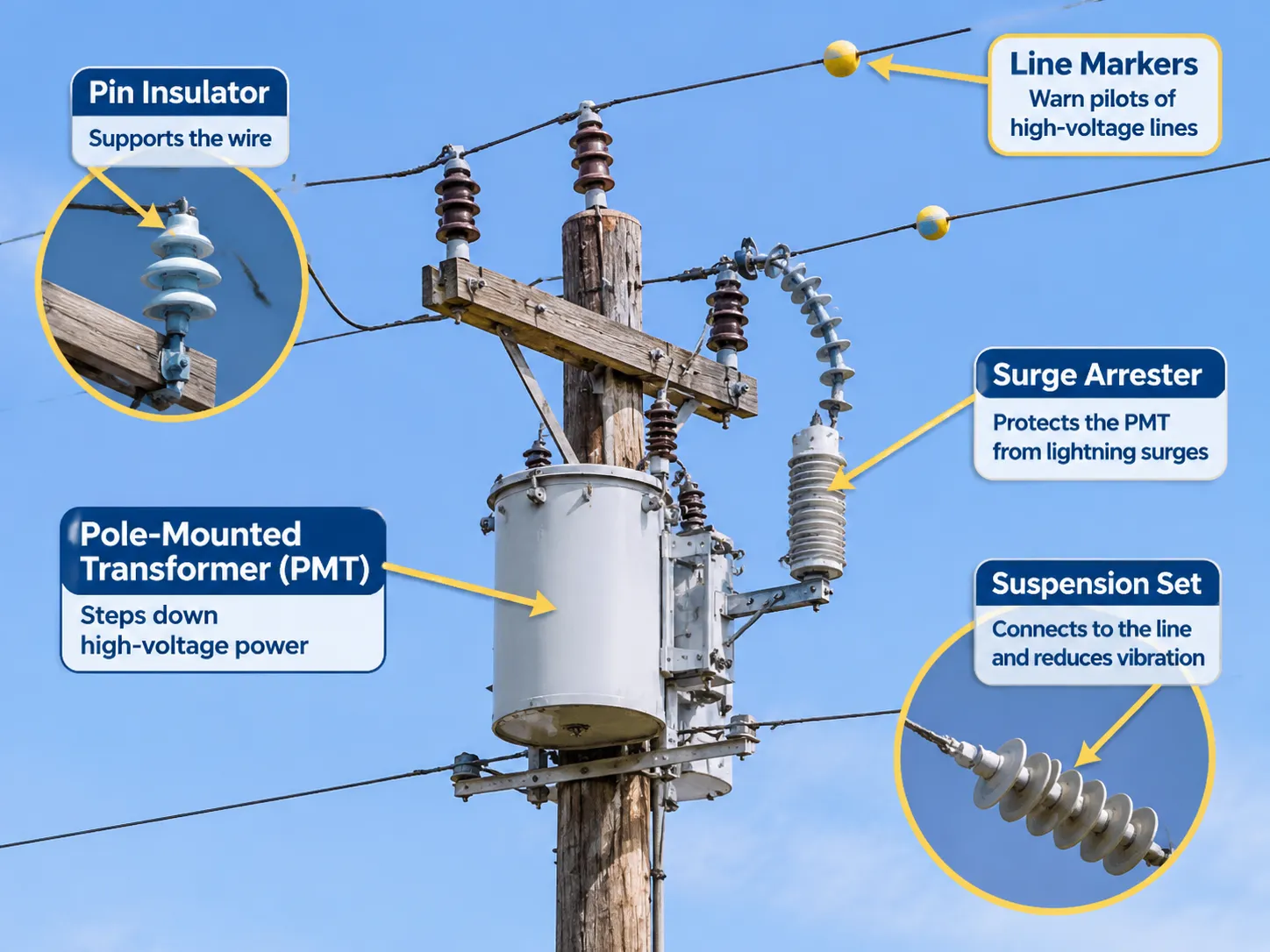
Cosa sono le cose rotonde sui pali
Un trasformatore montato su palo (PMT) si trova tipicamente nella parte superiore di un palo. Il PMT consiste in un cilindro sigillato, o serbatoio, che ha passacavi montati sulla parte superiore per collegarsi ai fili aerei. Sebbene il PMT non sia un isolatore, spesso viene confuso con un isolatore da chi lo osserva.
I piccoli oggetti rotondi, o isolatori a perno, si trovano sui traversi adiacenti al PMT; la configurazione a stringa di dischi (un “set di sospensione”) serve come collegamento tra il PMT e la linea di distribuzione. L'arrestatore di sovratensione (il cilindro bianco o grigio montato accanto al PMT) è progettato per proteggere il PMT dalle sovratensioni causate dai fulmini e dall'energia correlata che viaggia lungo le linee elettriche.
I marcatori colorati attaccati al filo ad alta tensione tra gli spacers indicano ai piloti che un aeromobile deve ottenere l'autorizzazione prima di volare vicino alla linea; gli anelli o i piccoli dischi al punto di sospensione forniscono un mezzo per ridurre le vibrazioni.
I termini che un acquirente usa effettivamente, e perché è importante
Questo potrebbe anche essere frainteso dagli acquirenti perché in inglese la parola “insulator” può riferirsi a tre prodotti distinti. Quando una persona può chiedere “insulators for the 33 kV substation”, potrebbe riferirsi a isolatori a colonna, dischi di sospensione o boccole, e tutte e tre queste risposte sarebbero appropriate. Il termine russo ввод è il termine corretto per boccole e non è intercambiabile con изолятор, che si traduce in inglese come insulator; similmente, in cinese il termine 套管 indica bushing e 绝缘子 indica insulator. In una specifica scritta, quando redatta in più lingue, il numero di parte e il disegno hanno priorità sulla terminologia.
Per gli acquisti, i seguenti quattro elementi elimineranno qualsiasi confusione che potrebbe verificarsi: ogni elemento specificherà la funzione (passaggio/supporto/sospensione), il tipo di isolamento elettrico (tensione nominale/classe di isolamento), la classificazione meccanica e la distanza di percorso superficiale per quel tipo di isolatore. Questo permetterà al fornitore di quotare con precisione il prodotto appropriato nonostante eventuali errori di etichettatura da parte loro.
Materiali: porcellana, vetro, composito, epossidico e carta
Porcelain is traditionally used; it is strong in compression; it remains stable/usable outdoors for decades, and its surface remains smooth and clean from deposits caused by pollution. The downside of porcelain insulators is that they are brittle and may break and not be visibly discernible until viewed from below. Tempered glass is generally used for suspension discs; however, it has a higher dielectric strength per millimetre than any other type of insulator and because it fails in a visible manner, it is easier to inspect, although it does come at an increased cost in both weight and the possibility of producing fragments upon failure.
Composite insulators are constructed of a fibreglass core with a silicone rubber shed. Porcelain and tempered glass electrical insulator materials have been the standard for years, but currently some manufacturers are offering composite type (silicone + FRP) electrical insulators which have many relative advantages over the previous two materials. Compared to porcelain and tempered glass, composite insulators are generally lighter in mass, provide better resistance to vandalism, operate satisfactorily in areas where airborne pollution is heavy, and typically composite insulators are manufactured with a hydrophobic (water repellent) coating on their outer surfaces. The hydrophobic coating is a factor in the performance of the composite insulator because while it provides some protection against moisture intrusion, it does not provide long term tracking resistance against moisture and UV radiation. The most significant issue affecting moisture and UVA tracking resistance in a composite insulator is the quality of the bond between the shed and the core. The bond quality can differ between manufacturers greatly. Epoxy cast resin is used to manufacture indoor switchgear bushings and post insulators, where the material can be cast to form a compact shape, while oil impregnated paper (OIP) is used within condenser bushing cores to control field grading between the coils and the OIP.
There are many types of materials currently available for use as the primary insulator in transmission and distribution electrical systems. As described earlier in this document, Porcelain, Tempered Glass and Composite Electrical Insulators are generally considered high strength materials with a high level of reliability. However, each material has both advantages and disadvantages as listed below.
| Materiale | Main use | Forza | Weakness |
|---|---|---|---|
| Porcelain | post insulators, bushings | long life, stable surface | brittle, cracks hidden |
| Tempered glass | suspension discs | visible failure, high strength | weight, fragments |
| Composite (silicone + FRP) | transmission, polluted sites | light, hydrophobic, vandal resistant | bond quality varies |
| Epoxy cast resin | indoor switchgear | compact, precise shape | limited to indoor or protected |
| OIP paper | condenser bushing core | controlled field grading | moisture sensitive |
Creepage and why the number of discs matters
Creepage distance is the distance measured along an insulated surface from the live part (bus or conductor) to earth. Creepage distance is specified for each unit of line voltage. Each line voltage is different due to environmental conditions (pollution levels). Creepage distance is measured at the following values depending on pollution level at the site:
| Pollution level | Creepage distance |
|---|---|
| Light | 25 mm/kV |
| Medio | 31 mm/kV |
| Heavy | 35–40 mm/kV |
The level of pollution (airborne) is determined by the environment and is not a personal preference of the Specification Writer. If a substation is located near a cement plant, in a coastal environment where it experiences exposure to salt spray, or in a location with a high concentration of conductive-type-dust; then you need the higher figure. The consequence for using an inappropriate number would be that you may have flashover during the foggy conditions rather than at the time of commissioning.
The meaning of this number is that it is also the reason that two insulators may be rated differently even though they are both the same height. The taller insulator has many more ribs, which will provide a longer creepage path compared to an insulator that is shorter and has widely spaced ribs that have been moulded deep into the insulator and have the appearance of being more robust. However, when the creepage path is analysed, the taller insulator has the higher creepage rating because it has a longer creepage path. The drawing provided in the standard gives the creepage percentage rating for each insulator, regardless of appearance.
Most of the packages used for substation equipment will have the same creepage requirement stated on the information sheet for each of the insulators used for that package, so that when the bills of material are created, they will list the packages based on pollution level, and then by voltage level, which is true for substation equipment within the same high voltage substation equipment range.
Where to buy, and what a set costs
There are three avenues to purchase these insulators and you cannot interchange them. The first one is from the original equipment manufacturer. When you are purchasing a bushing for a transformer, you purchase the bushing from the transformer manufacturer, and they guarantee that the bushing fits and that the field grading is correct. You can purchase the bushing separately from an existing transformer, but in that case, you are required to know the drawing, and the flange dimensions. The second group is the bushing and insulator component manufacturers; they each have a dedicated factory that manufactures these components and sells them direct to transformer manufacturers as well as electric utility companies. They can provide a spare set based on the original part’s drawing; this is typically the only way to acquire a replacement or upgraded version. The third type of manufacturer is the MRO distributor, which stocks common ratings of both bushings and insulators for immediate delivery at an extra cost of approximately 30% to 50% above standard pricing.
| Voce | Tensione | Indicative price (USD) | Tempi di consegna |
|---|---|---|---|
| Porcelain bushing, transformer | 12–24 kV | 60–250 each | 1–3 weeks |
| Composite bushing, transformer | 36 kV | 180–500 each | 2–4 settimane |
| Condenser OIP bushing | 145 kV | 4,000–18,000 each | 8–20 settimane |
| Post insulator | 12 kV | 30–120 each | 1–3 weeks |
| Suspension disc (70 kN class) | per unit | 6–25 each | 1–4 weeks |
| Corona ring | matching 145 kV | 150–600 each | supplied with the fitting |
These pricing indications are for budgetary purposes only and are not representative of what you would pay if you were to place a purchase order. The broad bands within the price ranges reflect the individual manufacturer’s cost to produce the insulators and bushings; there will be significant differences between an insulator supplied with only a Declaration of Conformity vs an insulator supplied with a full set of test documentation including routine test reports and type test certificates (the difference being approximately 20%-40% on average).
For orders in which insulators are included as part of an equipment package (e.g., in conjunction with other components such as transformers), it is more practical to purchase the insulators/insulator assemblies together as opposed to separately. By purchasing the assembly as a whole, it is much easier for the equipment designer/manufacturer to coordinate the interface of all of the components (the dimensions of the mounting flanges, creepage level, and corona ring) as opposed to each component having separate suppliers and potentially conflicting requirements; it is not uncommon for this to occur in the case of high voltage electrical equipment packages.
Manufacturers worth knowing
Three established names in insulator manufacturing are NGK Insulators (Japan), Sediver (France – glass) and Lapp Insulators (Germany – porcelain and composite). These companies comprise most of the global supply of transmission-class discs and posts and their catalogues serve as the reference for disc dimensions and mechanical class.
Trench Group is well respected as the manufacturer of bushings, while Hitachi Energy and ABB offer bushings as part of transformer and switchgear packages. The type-test documentation is what a utility specification usually cites for bushings. In many distribution-level projects, utilities will have two options: Either a regional factory that can supply an equivalent rating with a routine test report at a lower cost, or a classic global brand that has a longer history of field use. Both options are acceptable, and the deciding factor will be how the utility’s standard specification identifies a brand as an acceptable source. A mandated list will uniquely identify the source of supply.
When insulators are subcomponents of a transformer or switchgear order, the assembly supplier has responsibility for supply of the insulator(s), and the component range of insulators is provided under “Electrical Substation Components“.
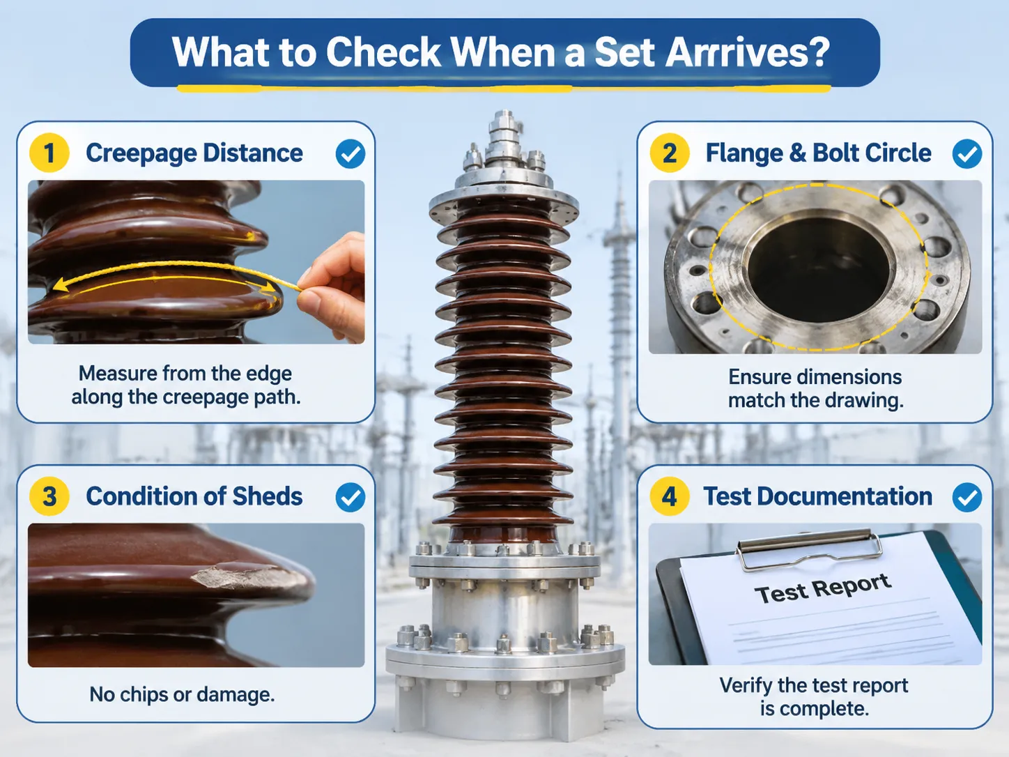
What to check when a set arrives
Four checks identify most issues, and none of these checks necessitate laboratory testing. The first check is the creepage distance compared to the drawing. Measuring the creepage distance is simply a matter of measuring from the edge of the insulator along the creepage distance with a piece of string, and even a creepage distance that is as little as ten percent short of what it should be, will cause the pollution class of the installation to be reduced.
Flange and bolt circle dimensions are the second most important aspect of bushing compatibility to the tank flange; if they do not match (i.e. are not the same), gaskets can not be installed and fluid can leak from the bushing to the tank. Condition of sheds is another critical aspect to the overall quality of the bushing. Chipped sheds on porcelain are not merely cosmetic; chips create a moisture trap and point where the electric field concentrates, which creates the potential for failure under most specifications. Test documentation is also crucial to bushing design. Normally, a unit test report is created for bushings; the type testing report provides the design-based information for the bushing and does not provide any testing information specific to the bushing. This same documentation logic applies to current transformers, whereas the numerous designs and schedules on the high-voltage current transformers document how the schedule of tests is attached to the individual unit and not to the batch of units it was tested with.
Domande frequenti
What are the round things on electric poles?
Typically, those are pole mounted transformers; they are sealed cylindrical tanks rather than insulators. The little circular objects on the crossarm just above the pole are pin insulators; the white cylinder that is bolted to the side of the transformer is a surge arrester that protects the transformer from lightning.
What are the types of insulators used in substations?
There are multiple styles of electrical insulators used in substations. These styles include post insulators for mounting bus bars, suspension insulators to support cables between towers, bushings to allow conductors to pass through grounded barriers, and enclosed apparatus insulators used within switched electrical gear and instrumentation transformers. Of these, the first three types tend to be visible and, therefore, will be what you see when looking at a substation from outside of the perimeter fence.
What are the circle things on power lines?
The circular coloured balls attached to high-voltage transmission lines are marker balls that warn pilots of the presence of the transmission lines below them. The smaller circular rings that fall within the anchor/support section of the transmission line serves as a vibration damper to help reduce the aeolian vibrations created by wind-induced movement. In contrast to those balls and rings, an insulator does not conduct electricity, so neither item should be mistaken for an insulator.
What does an insulator do in a substation?
Electrical insulators support live electrical components and separate them from energized portions of the operation and the ground as well as hold the electrical bus bars or overhead conductors in place; during normal operation, however, the insulator itself carries no current. The way an insulator works is determined primarily by the creepage distance, the mechanical load(es) and, depending on the use of the insulator as a long-term insulator, the levels of pollutants present in the environment.
Why is a bushing different from an insulator?
Yes, the primary distinction is that bushings hold conductor cables inside of them, whereas insulators do not carry current in any manner. This key difference between bushings and other forms of electricity-related tooling affects how bushings and other forms of electrical insulating products are designed, tested and, ultimately, how they fail when exposed to environmental conditions. Bushings fail when subjected to the presence of moisture and/or paper deterioration and by contrast, insulators fail primarily through surface flashover or mechanical breakage.
Riferimenti
- Trench Group — High Voltage Bushings and Coil Products
- NGK Insulators — Transmission and Substation Insulators
- Sediver — Toughened Glass Insulators
- Lapp Insulators — Porcelain and Composite Insulators
- Hitachi Energy — Bushings and Substation Equipment
Conclusione
In conclusion, as we noted previously, the round or cylindrical items visible in the substations associated with electric utilities serve three distinct functions. First, as stated, bushings contain conductors travelling through the center of the bushing and serve the purpose of transferring electricity through themselves as normal insulators do. The next round object is the insulated supports; and lastly, the third reason round objects exist within substations relates to the corona rings and their role in shaping and forming the field surrounding the bushing; these do not touch anything.
As such, the importance of specifying the correct terminology associated with bushings (i.e., name, function, voltage class, mechanical rating and creepage distance) is paramount for determining the precise insulator components supplied when requested by the electrical utility customer.