


델타 와이 변압기는 현대 산업 및 상업에서 널리 사용되는 삼상 전기 시스템 중 하나입니다. 전기 엔지니어들은 델타 와이 시스템을 활용하여 중전압 배전 유틸리티 시스템을 저전압 배전 시스템으로 변환하고 그 반대의 경우도 수행하며, 따라서 프로젝트의 성공적인 완료를 위해 적절한 장비를 선택하기 위해 그 전자기 과정, 벡터 관계 및 부하 역학에 대한 지식을 갖추는 것이 매우 중요합니다. Subian Electric에서는 고효율 오일 침지 변압기 시스템과 신뢰할 수 있는 건식 변압기 및 패드 장착 변전소를 포함한 전문 배전 장치가 IEEE C57, ANSI, IEC 60076와 같은 다양한 국제 기준을 따릅니다. 이 기사는 델타-와이 연결에서 삼상 변압기의 기본을 설명하며, 다양한 국가의 전기 공학 프로젝트에 대한 중요성을 설명합니다.
기본 정의: 델타와 와이 연결 유형의 차이를 배우기
델타-와이 변압기가 어떻게 작동하는지 이해하려면, 다상 AC 시스템에서 두 가지 기본 연결 유형인 델타(Δ, 메쉬) 연결과 와이(Y, 스타) 연결부터 시작해야 합니다.
델타(Δ) 토폴로지
델타 토폴로지에서는 세 개의 단상 코일이 직렬로 연결되어 닫힌 삼각형 루프를 형성합니다. 그 후 위상 단자는 세 개의 연결 노드로 연결됩니다. 닫힌 기하학적 도형이 형성되므로:
– 선간 전압은 위상 코일 전압과 같습니다: V_line = V_phase.
– 선의 전류는 균형 상태에서 위상 코일 전류에 √3을 곱한 값과 같습니다: I_line = √3 * I_phase.
– 위상 전류는 위상 순서에 따라 선 전류보다 30°의 전기 각도로 지연되거나 선 전류를 선도합니다.
– 델타가 단순한 삼선 회로로 사용될 경우, 실제 중성점이 없으므로 삼상 부하를 접지 장치 없이 단순히 델타 권선으로 시작할 수 없습니다.
와이(Y) 토폴로지
와이 또는 스타 구성에서는 각 위상 코일의 시작 부분이 중성점으로 알려진 공통 노드에 서로 연결됩니다. 다른 끝은 세 개의 선 또는 위상에 연결됩니다. 이를 통해 전압과 전류 간의 관계가 설정됩니다.
– 선 전류는 위상 전류와 같습니다: I_line = I_phase, 각 선의 전류가 동일하다는 가정 하에.
– 선간 전압은 선-중성 전압의 √3배와 같습니다: V_line = √3 * V_phase (예를 들어, 480V 선간 전압은 277V 선-중성 전압을 의미하며, 400V 선간 전압은 230V 선-중성 전압을 의미합니다).
– 선간 전압은 선-중성 전압보다 30° 앞설 수 있습니다.
– 중성점은 와이를 접지할 수도 있고, 신뢰할 수 있는 삼상 사선 시스템을 구축하는 전선 역할을 할 수도 있어 단상 및 삼상 부하를 모두 제공할 수 있습니다.
델타 와이 변압기의 작동 원리: 핵심 전자기 원리
삼상 변압기는 패러데이의 전자기 유도 법칙과 앰페어의 회로 법칙에 따라 작동합니다. 삼상 중간 전압 공급이 기본 델타 단자(H1, H2, H3)에 연결될 때마다 교류가 기본 권선으로 흐릅니다.
전류의 이러한 변화는 고투과성 결정 방향 실리콘 강철 또는 비정질 금속으로 구성된 코어 내에서 자기장을 생성합니다. 기본 회로는 두 개의 들어오는 선 도체를 가로지르는 델타 구성으로 배열되어 있으므로 전류의 전체 기본 공급을 경험합니다.
각 다리의 코어에서 생성된 자기장은 동일한 다리에 배치된 권선에 직접 연결됩니다. 변압기의 권선 비율(N1/N2)에 따라, 2차 권선의 전압은 기본 권선의 전압에 비례하여 생성됩니다. 델타 와이 변압기에서는 모든 2차 권선이 중성 버스바에 연결되어 있으며, 세 개의 2차 권선의 전압은 부싱(X1, X2, X3) 간의 전압입니다.
단계별 전압 및 전류 변환
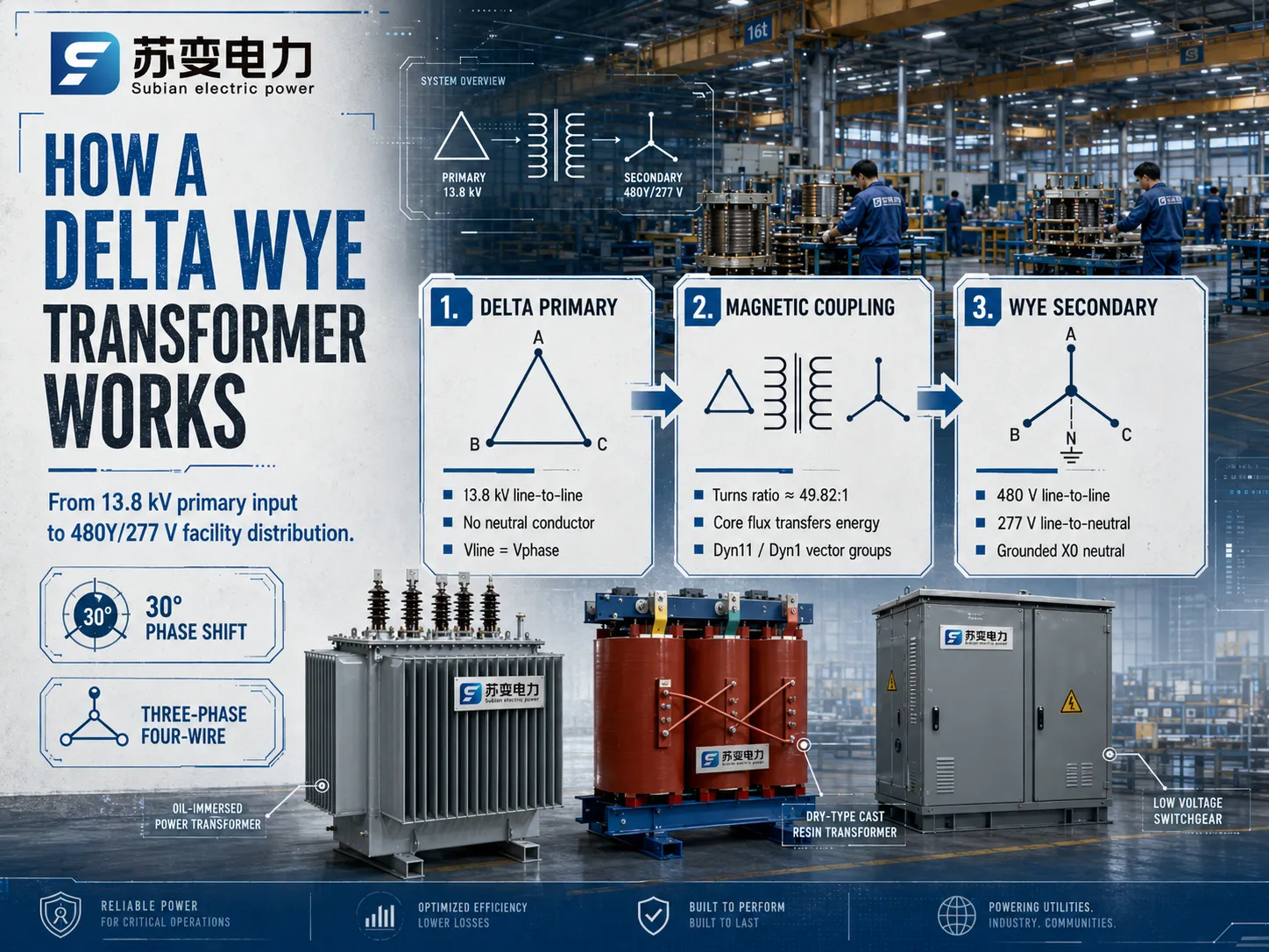
델타 와이 다운 변압기의 전력 흐름을 측정하기 위해, 우리는 Subian Electric에서 제조한 산업용 변압기 하나를 사용할 것입니다. 이 변압기는 기본 13,800V 공급의 전압을 시설에서 사용하는 480Y/277V로 변환합니다.
기본 단계의 단계: 기본 시스템에서 13.8 kV 유틸리티는 삼상 도체를 전송하며 중성 도체가 없습니다. 따라서 중성이 없는 선 대 선으로 연결되어 있으며, 이는 13,800V로 정격되어 있음을 의미합니다.
전자기 결합: 이제 위상 전압에 따라 권선 비율을 계산해야 합니다. 2차 권선은 277V(480V / √3)의 출력을 제공합니다. 따라서 변압기의 실제 물리적 권선 비율은 13,800V : 277V로, 권선 비율은 약 49.82:1입니다.
마지막으로, 2차 생성: 277V 출력을 가진 세 개의 코일이 와이 형식으로 연결되면 두 개의 활성 위상이 480V의 전압을 생성합니다.
벡터 그룹, 각 변위 및 위상 이동
변압기가 델타에서 와이 구성으로 전환될 때 전압 벡터에 기하학적 이동이 발생합니다. 다변량 전기 공학에서 발생하는 각 위상 이동은 IEC 60076 및 IEEE의 사양에 따라 시계 표기법으로 나타냅니다.
Dyn11 벡터 그룹
다양한 국제적으로 지정된 벡터 그룹 중에서 Dyn11 벡터 그룹이 가장 많이 사용됩니다.
D: 기본 고전압 권선은 델타 구성으로 연결됩니다.
y: 2차 저전압 권선은 와이 구성으로 연결됩니다.
n: 중성선이 외부로 가져와져 쉽게 연결할 수 있도록 합니다.
11: 저전압 선 대 중성 벡터는 고전압 선 대 선 벡터를 30도 각도로 이끌며(이는 한 시간이 30도에 해당하는 시계에서 11시를 나타냅니다).
Dyn1 벡터 그룹
반면, 북미의 일부 지역 전력망에서는 Dyn1 벡터 그룹을 사용하는 설치가 있습니다. 여기서의 방법은 저전압 벡터가 고전압 벡터에 대해 30도(1시 방향에 해당)만큼 지연된다는 것입니다. 두 변압기 유형은 전력 변환 및 고조파 감쇠 측면에서 동일하지만, 서로 다른 벡터 구성(예: Dyn11 대 Dyn1)은 병렬로 연결할 수 없습니다. 서로 다른 위상 이동 기술을 가진 변압기를 병렬로 배치할 경우, 각 위상 간의 전압 각도 차이가 증가하여 심각한 위상 간 단락이 발생합니다.
델타 와이 구성의 주요 엔지니어링 장점
전력 시스템 설계자는 델타 와이 변압기 여러 중요한 전기 성능 이유로 대체 배열(예: 와이-와이, 델타-델타 또는 와이-델타)보다 선택합니다.
| 변압기 구성 | 중성선 가용성 | 제3 고조파 동작 | 불균형 부하 허용 | 일반적인 응용 프로그램 |
|---|---|---|---|---|
| 델타 – 와이 (Δ – Y) | 예 (2차 X0) | 1차 델타 루프에 갇힘 | 우수함 (중성이 불균형을 처리함) | 산업 배전, 상업 시설, 패드 장착 변전소 |
| 와이 – 와이 (Y – Y) | 예 (양쪽 모두) | 제3 델타가 존재하지 않으면 중성이 떠 있을 수 있음 | 안정화되지 않은 중성선이 없는 경우 | 고전압 송전 연결선 |
| 델타 – 델타 (Δ – Δ) | 아니오 (접지 뱅크 필요) | 두 개의 델타 루프에 갇힘 | 보통 (한 상이 고장 나면 오픈 델타에서 작동 가능) | 중량 산업용 모터 부하, 고립된 델타 발전소 |
| 와이 – 델타 (Y – Δ) | 예 (주 전원만) | 2차 델타 루프에 갇힘 | 보통 | 발전기 승압 변압기 (GSU) |
제3 고조파 전압 제거
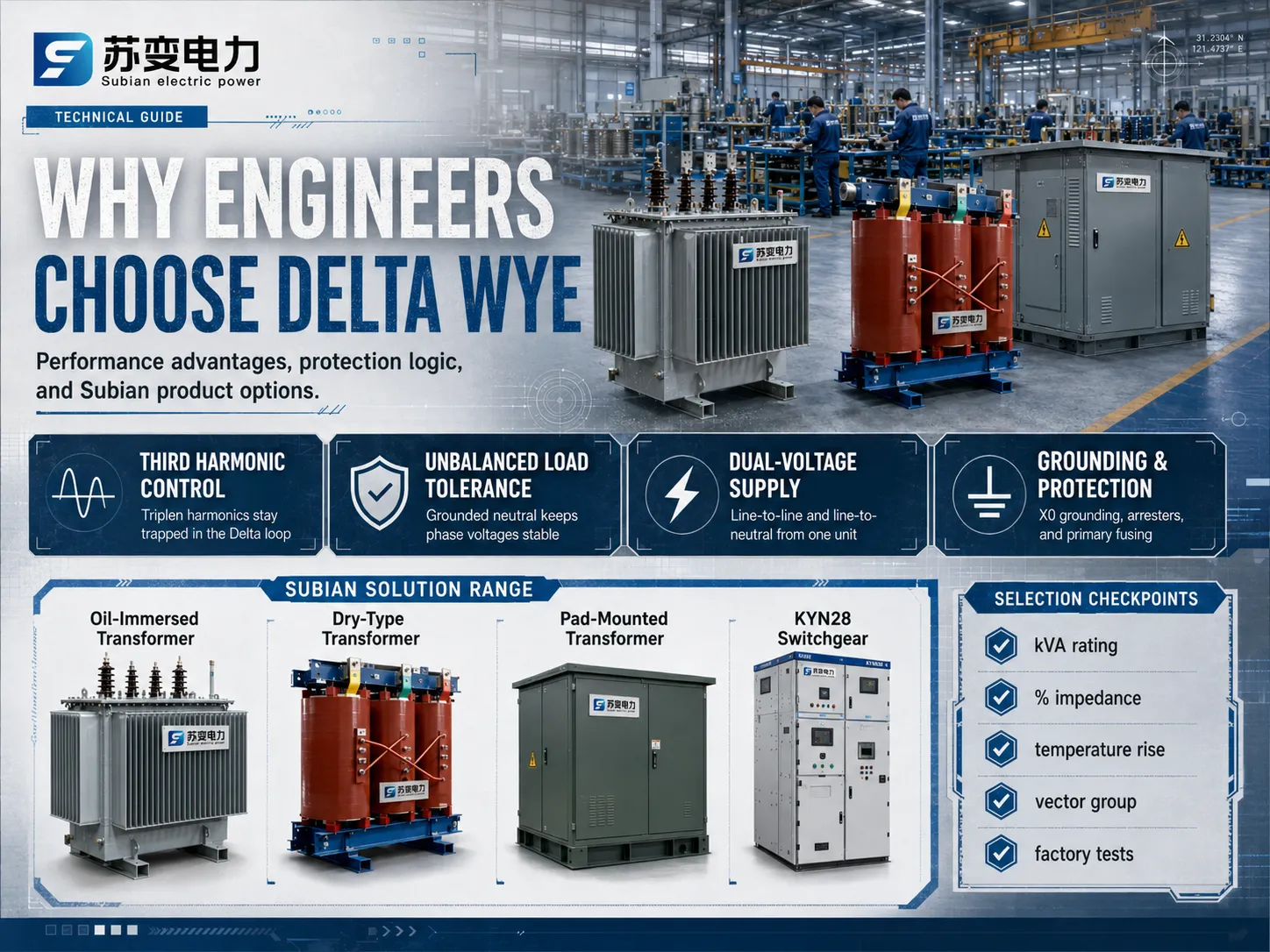
가변 주파수 드라이브 (VFD), 정류기, 컴퓨터 전원 공급 장치 및 LED 조명과 같은 비선형 부하는 주로 3차 고조파(60Hz 시스템에서 180Hz, 50Hz 시스템에서 150Hz)가 풍부한 전류를 끌어옵니다. 제3 고조파 전류는 제로 시퀀스 성분으로, 모든 세 전기 상에서 서로 완벽하게 위상이 일치합니다.
에서 델타 와이 변압기, 2차 측에서 생성된 모든 제로 시퀀스 고조파 전류는 주 권선으로 반사됩니다. 주 권선은 폐쇄된 델타 회로를 형성하므로, 이러한 위상이 일치하는 제3 고조파 전류는 삼각형 루프 내부에서 무해하게 순환하며 주 송전선으로 빠져나갈 수 없습니다. 이 효과적인 제3 고조파 억제 상류 통신 간섭을 방지하고, 시스템 전체의 전압 왜곡을 줄이며, 상류 유틸리티 장비의 심각한 과열로부터 보호합니다.
강력한 불균형 부하 처리
상업 및 주거 시설에서는 단상 부하가 세 상에 걸쳐 절대적인 수학적 대칭으로 분배되는 경우가 드뭅니다. 2차 와이 측에서 불균형 상태가 발생하면 중성선(X0)을 통해 상당한 복귀 전류가 흐릅니다. 2차 중성이 물리적으로 접지되어 있기 때문에 이 불균형 부하 처리 기능은 상-중성 전압이 안정적으로 유지되도록 보장하며, “중성점 이동” 또는 “부유 중성”으로 알려진 상 전압 왜곡을 유발하지 않도록 하여 접지되지 않은 와이-와이 변압기에 자주 발생하는 문제를 방지합니다.
동시 이중 전압 공급
2차 와이 연결은 단일 장치에서 두 가지 뚜렷한 사용 전압 수준을 제공합니다:
- 상간 전압: 냉각기, 펌프, 기계 공구 및 제조 공정 라인과 같은 대형 삼상 유도 부하에 전력을 공급합니다.
- 상-중성 전압: 단상 건물 부하, 일반 사무실 콘센트, 건물 자동화 전자 장치 및 건축 조명 기구에 전력을 공급합니다.
이 이중 전압 유연성은 시설 스위치기어 아키텍처를 대폭 단순화하고 보조 승압 변압기에 대한 초기 자본 지출을 줄입니다.
코어 포화 및 돌입 전류 제어
삼상 장치의 자기 코어 설계는 에너지를 공급하고 고장을 제거하는 동안 비대칭 플럭스 조건을 처리해야 합니다. 폐쇄된 델타 루프는 제로 시퀀스 플럭스가 심각한 탱크 가열을 일으키는 것을 방지하므로, 구조용 강철 인클로저 내의 기생 와류 전류를 최소화하여 절연유 또는 고체 주입 다이렉트 수지의 작동 수명을 연장합니다.
수비안 전기 변압기 솔루션: 까다로운 그리드를 위한 설계
적절한 배전 장비를 선택하는 것은 고품질 생산, 복잡한 금속 가공 및 철저한 유전체 테스트가 포함되기 때문에 중요합니다. Subian Electric는 도시 유틸리티, 거래 지역, 산업 구역 및 환경 친화적인 생산 시설을 위한 모든 종류의 전력 변환 시스템을 설계하고 생산하는 데 전문화되어 있습니다.
Subian 오일 침지 배전 변압기
야외 변전소, 유틸리티 전주 설치 및 산업 플랜트 변전소를 위해, 오일 침지 변압기 Subian Electric의 시리즈는 우수한 열 방산 및 유전체 내구성을 제공합니다:
- 코어 기술: 스텝 랩 미터 조인트가 있는 고급 냉간 압연 결정 지향 (CRGO) 실리콘 강판으로 제작되어 무부하 손실을 크게 줄이고 운영 소음 수준을 감소시킵니다.
- 권선 구조: 고전도 전해 구리 또는 고급 전기 알루미늄 도체가 업그레이드된 열 등급 절연지를 특징으로 합니다. 고전압 코일은 단락 전자기 스트레스를 견딜 수 있도록 견고한 디스크 또는 층 설계로 배열됩니다.
- 냉각 매체: 고유전율 미네랄 절연유(또는 요청 시 생분해성 자연 에스터 액체)는 빠른 대류 열 추출과 지속적인 전부하 작동 조건에서 긴 절연 수명을 보장합니다.
Subian 드라이 타입 주형 수지 변압기
고밀도 상업 타워, 지하 철도 시스템, 의료 시설 및 오일 가연성이 용납될 수 없는 안전 위험을 초래하는 실내 변전소에서, 건식 변압기 Subian Electric의 범위는 최적의 화재 안전 및 습기 저항을 제공합니다:
- 진공 압력 주조: 고전압 권선은 고진공 상태에서 순수 에폭시 수지로 캡슐화되어 미세한 공기 구멍을 제거하고 부분 방전 수준을 10 pC 이하로 유지합니다.
- 환경 분류: 국제 기후(C2), 환경(E2) 및 화재 행동(F1) 성능 기준을 충족하도록 설계되어 습기, 화학적으로 공격적이거나 먼지가 많은 환경에서도 운영 신뢰성을 보장합니다.
- 낮은 유지보수: 샘플링, 필터링 또는 교체할 액체 유전체가 없기 때문에 주형 수지 장치는 매우 낮은 생애 주기 운영 비용을 제공합니다.
Subian 패드 장착형 구획 변압기
상업 소매 센터, 교육 캠퍼스, 데이터 센터 및 재생 가능 에너지 생성 사이트에 서비스를 제공하는 지하 전기 배전 시스템을 위해, Subian Electric는 변조 방지 패드 장착 변압기 패키지:
- 통합 안전 구획: 중전압 케이블 종단 챔버와 저전압 단자 구획을 나누는 변조 방지 잠금 구획이 있는 중량 게이지 아연 도금 강철 인클로저.
- 루프 또는 방사형 공급: 두 위치 또는 네 위치의 오일 하중 차단 스위치를 사용하는 방사형 단일 연결 또는 루프 공급 배전 시스템에 맞게 구성됨.
- 재생 가능 에너지 통합: 맞춤 설계된 재생 가능 에너지 승압 변압기 유틸리티 규모의 태양광(PV) 인버터 스테이션 및 풍력 발전 집합망을 위해, 인버터 AC 출력을 직접 11 kV, 22 kV 또는 33 kV 집합망으로 승압합니다.
변압기 크기 및 엔지니어링 선택 기준
조합 변압기를 지정하는 것은 델타 와이 변압기 단순 kVA 등급을 넘어서는 운영 매개변수를 평가해야 합니다. 전기 엔지니어는 조기 열 노화 또는 예기치 않은 트립을 피하기 위해 부하 프로필, 고장 내성 및 환경 조건을 계산해야 합니다.
겉보기 전력(kVA) 계산
총 겉보기 전력 등급은 지속적인 정상 상태 수요와 예상되는 피크 과부하 조건을 수용해야 합니다. 삼상 시스템의 경우 필요한 용량은 다음에 의해 결정됩니다:
kVA = (√3 × V_line × I_line) / 1000
가변 주파수 드라이브 또는 데이터 센터 서버의 고농도에 전원을 공급하는 장치를 크기 조정할 때, 설계자는 감쇠 계수를 포함하거나 고조파 부하 전류로 인한 도체의 와전류 손실을 관리하기 위해 K-팩터 등급 변압기(예: K-4, K-13, K-20)를 지정해야 합니다.
퍼센트 임피던스 (%Z) 및 단락 계산
변압기의 내부 누설 임피던스 (%Z)는 전압 조정과 단락 전류 제한 간의 균형을 설정합니다:
- 저임피던스 (예: 3.5% ~ 4.5%): 중량 부하 변동 시 전압 조정을 개선하고 대형 모터 시작 시 전압 강하를 줄입니다. 그러나 이는 더 높은 예상 고장 전류를 초래하여 하류 스위치 기어 및 차단기가 더 높은 차단 용량(kA 등급)을 요구합니다.
- 고임피던스 (예: 5.75% ~ 7%): 단락 고장 전류 수준을 제한하여 하류 보호 장치 및 배선을 보호합니다. 단점은 중량 유도 부하에서 약간 더 높은 전압 강하입니다.
온도 상승 및 절연 등급
Subian Electric는 여러 열 절연 등급의 변압기를 제작합니다. 액체로 채워진 장치에서는 표준 설계가 30°C 평균 환경 기준에서 65°C 평균 권선 온도 상승을 제공합니다. 주형 수지 건식 시스템에서는 Class F (155°C) 및 Class H (180°C) 절연 재료가 100°C 또는 115°C 온도 상승에서 지속적인 신뢰할 수 있는 작동을 허용하며, 내장된 열 과부하 여유를 제공합니다.
델타 와이 설치에서의 중성 접지 및 시스템 보호
2차 스타 포인트 (X0)는 델타 와이 변압기 시설 안전 및 보호 릴레이의 기준점입니다. 이 중성 단자가 지구에 어떻게 연결되는지는 지락 고장 조건에서 전체 저전압 배전 네트워크의 동작을 결정합니다.
고정 접지 대 저항 접지
- 고정 접지 중성: X0 단자는 저항이 낮은 도체로 시설 접지 전극 시스템에 직접 연결됩니다. 상-지락 고장 시, 상당한 고장 전류가 즉시 흐르며, 과전류 보호 장치(몰딩 케이스 차단기, 전자 트립 유닛 또는 퓨즈)가 고장 회로를 신속하게 차단할 수 있습니다. 이는 상업용 건물 전기 서비스에서 표준 관행입니다.
- 저항 접지 (LRG): 중성 접지 저항기(NGR)가 X0와 지구 접지 사이에 삽입되어, 일반적으로 지락 전류를 100A에서 400A 사이로 제한합니다. LRG 시스템은 지락 고장 시 아크 플래시 위험과 대형 모터에 대한 기계적 손상을 제한하기 위해 제지 공장, 정유소 및 화학 공장과 같은 중공업 환경에서 널리 사용됩니다.
- 고저항 접지 (HRG): NGR은 지락 전류를 5A 또는 10A로 제한하여, 보호 장치를 즉시 작동시키기에는 부족합니다. 이는 운영자가 고장 난 선을 찾는 동안 중요한 연속 프로세스가 전원이 유지되도록 하여, 예기치 않은 정전을 방지합니다.
1차 과전류 및 낙뢰 보호
1차 델타 권선에는 중성 도체가 없기 때문에, 1차 유틸리티 피더의 상-지락 고장은 상류 변전소 차단기에 의해 차단되어야 합니다. 변압기 자체를 보호하기 위해:
- 서지 억제기: 금속 산화물 바리스터(MOV) 서지 억제기는 대기 중의 낙뢰 충격과 스위칭 서지를 안전하게 지구로 유도하기 위해 1차 부싱(H1, H2, H3) 바로 옆에 장착되어야 합니다.
- 1차 퓨징: 패드 장착 유닛에서는 베이오넷 전류 감지 또는 이중 감지 퓨즈가 내부 변압기 결함 및 2차 단자 단락으로부터 보호하기 위해 전류 제한 백업 퓨즈와 결합되어 있습니다.
공장 테스트 및 품질 보증 기준
발송 전에 운영 무결성을 보장하기 위해, 현대 전력 변압기는 국제 기준에 따라 엄격한 공장 수용 테스트(FAT)를 거칩니다:
- 권선 저항 측정: 모든 상 코일의 저항이 균형을 이루고 있는지 확인하여 도체의 무결성과 견고한 브레이징 연결을 확인합니다.
- 전압 비율 및 벡터 그룹 검증: 모든 탭 체인저 위치에서 정확한 권선 비율을 확인하고 30도 각도 위상 변위를 검증합니다(Dyn11 또는 Dyn1).
- 무부하 손실 및 자극 전류: 정격 전압에서 코어 손실 성능을 평가하여 코어 조립 품질 및 에너지 효율 준수를 확인합니다.
- 부하 손실 및 단락 임피던스: 구리 손실(I²R)을 정량화하고 내부 임피던스가 엔지니어링 사양과 일치하는지 확인합니다.
- 절연 내력 시험: 절연 강도를 확인하기 위해 회전 대 회전, 권선 대 권선, 및 권선 대 접지 절연 장벽에 대한 별도의 전원 주파수 AC 전압 시험 및 유도 과전압 시험이 포함됩니다.
- 낙뢰 임펄스 내력 시험: 고전압 과도 현상을 시뮬레이션하여 절연 시스템이 심각한 그리드 장애를 견딜 수 있도록 합니다.
델타 와이 변압기에 대한 자주 묻는 질문
배전 변압기의 1차 측이 일반적으로 델타 대신 와이인 이유는 무엇인가요?
델타로 1차를 연결하면 긴 유틸리티 송전 및 배전 거리에서 비싼 네 번째 중성 도체를 설치할 필요가 없어져 상당한 구리 또는 알루미늄 자재 비용을 절감할 수 있습니다. 또한 델타 루프는 자연스럽게 제로 순서 제3 고조파 전류를 가두어 상류 유틸리티 배전 네트워크를 오염시키는 것을 방지합니다.
델타 와이 변압기를 역으로 사용하여 전압을 상승시킬 수 있나요?
물리적으로 전자기 변압기는 양방향 장치입니다. 그러나 표준 델타 와이 변압기 역으로 전원을 공급하는 것(델타 측에서 전압을 상승시키기 위해 와이 권선에 중전압을 적용하는 것)은 기술적인 복잡성을 초래합니다. 정상적인 전력 흐름 방향은 최적의 코어 기하학 및 권선 구성을 결정하며, 역전력 흐름은 과도한 돌입 전류, 코어 포화 및 수신 측에서 부유 중성 문제를 일으킵니다. 적절한 접지, 크기 조정 및 보호 계전기가 시스템에 설계되지 않는 한 그렇습니다.
델타 와이 연결과 관련된 30도 위상 이동의 원인은 무엇인가요?
30도 위상 이동은 선 대 선 전압을 선 대 마이너스 전압에 연결하는 기하학적 및 수학적 결과입니다. 1차 델타 구성에서 선 전압은 위상 전압과 같습니다. 2차 와이 연결에서는 120도 떨어진 2개의 위상 전압 간의 벡터 차이를 기반으로 선 전압이 계산됩니다. 결과적으로 선 대 선 벡터는 위상 대 마이너스 벡터에 대해 정확히 30 전기 도만큼 이동합니다.
Dyn11과 Ynd11을 구별하는 것은 무엇인가요?
전통적인 벡터 그룹 표기법에서 첫 번째 대문자는 고전압 권선을 나타내고 두 번째 소문자는 저전압 권선을 정의하는 데 사용됩니다. 따라서 Dyn11은 중성 날개가 있는 고전압 델타 권선을 나타내며 저전압 와이 구성을 가집니다. 반대로 Ynd11은 중성 날개가 있는 고전압 와이 구성을 나타내며 저전압 델타 구성을 가지므로 이 구성은 일반적으로 대형 발전기 승압 응용에 사용됩니다.
결론: 회복력 있는 전력 배전 네트워크 구축
방법 델타 와이 변압기 상업, 산업 및 유틸리티 전력 분배의 기초가 됩니다. 델타에서 와이 변압기의 독특한 설계는 오늘날의 AC 시스템이 직면한 주요 문제를 해결하며, 기본 델타 권선의 전송 효율성과 고조파 억제를 결합하고, 이차 와이 권선의 이중 전압 작동의 유연성과 접지 안정성을 제공합니다.
주요 전기 원리에 대한 중요한 이해는 유틸리티 라인에서 작동하는 오일형 변압기, 건물 내부에 설치하는 드라이형 변압기 또는 재생 가능 전력을 수확하기 위한 맞춤형 패드 장착 변압기 등 다양한 변압기 유형의 사용을 가능하게 합니다. Subian Electric은 현대 전기 시스템의 요구 사항을 충족할 준비가 된 다양한 효율적인 전력 변압기를 제공합니다.