


저를 포함한 많은 사람들에게 이 유형의 장비를 설명하는 유일한 방법은 “둥근 것들”입니다. 이 둥근 부품들은 실제로 변전소 내에서 전류가 흐르는 가공 전선을 지지하는 자기관 전기 절연체이며, 다양한 변압기 부품이기도 합니다.
간단한 답변: 변전소에서 둥근 부품의 세 가지 주요 유형은 부싱, 절연체, 코로나 링입니다. 부싱은 접지된 장벽을 통해 고전압 선로나 도체를 통과시키는 데 사용됩니다. 절연체는 도체를 접지로부터 분리하고 지지하며, 여러 개의 절연체를 사용하여 다양한 높이에서 도체를 지지하는 기계적 지지 역할도 합니다. 코로나 링은 절연 장비에 가해지는 전기적 스트레스를 줄이는 메커니즘을 제공합니다. 부싱, 절연체, 코로나 링의 전문 명칭은 각각 부싱, 포스트 절연체, 서스펜션 절연체 및 코로나 링입니다. 절연체를 주문할 때는 특정 유형을 명확히 명시하는 것이 필수적이며, 그렇지 않으면 모호해질 수 있습니다.
이 글에는 각 부품 유형에 대한 설명, 기계적 및 전기적 기능, 부품이 원형인 이유, 필요한 디스크 수 결정 방법, 부품의 출처 요약이 포함되어 있습니다.
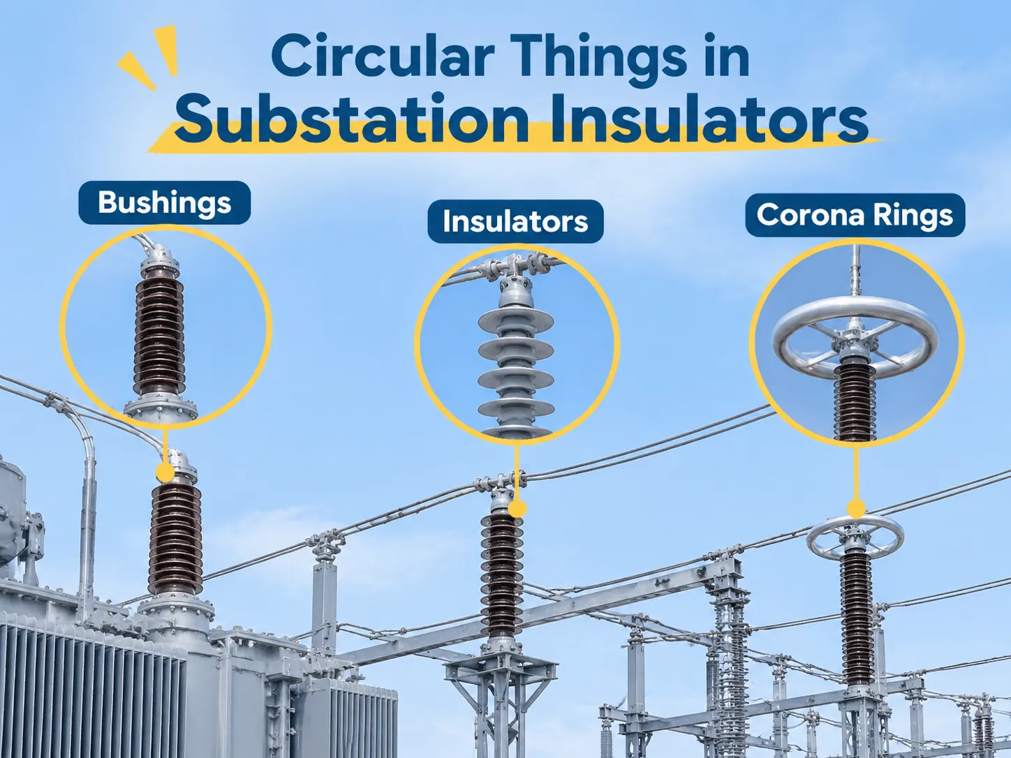
간단한 답변: 사람들이 “둥근 것들”이라고 부르는 세 가지 부품”
부싱은 접지된 장벽을 통과하는 도체의 통로입니다. 부싱은 도체가 접지된 장벽(예: 변압기, 개폐기, 벽)을 통과할 때 절연을 유지하도록 하는 절연 통로 역할을 합니다. 부싱은 지지대 역할을 하지 않으며 분리기 역할도 하지 않습니다. 부싱은 전선을 위한 절연된 문과 같습니다.
절연체는 도체를 지지하고 분리하는 역할을 합니다. 포스트 절연체는 변압기를 위해 버스바를 지지합니다. 서스펜션 절연체(갠트리에서 도체까지)는 갠트리에서 도체를 지지합니다. 정상 작동 시 두 절연체 모두 전류를 전달하지 않으며, 전압을 유지하면서 기계적 하중을 지탱합니다.
코로나 링은 지지대도 분리기도 아닙니다. 코로나/그레이딩 링은 피팅 주위에 볼트로 고정된 금속 토러스 형태로, 피팅 주변의 전기장을 재형성하도록 설계되었으며, 최대 전기장 강도 지점에서 토러스가 활선 도체와 접촉하지 않도록 설계되었습니다.
| 당신이 보는 것 | 구성 요소 | 전류를 전달함 | 하중을 전달함 | 일반적인 위치 |
|---|---|---|---|---|
| 변압기 덮개 위의 자기관 실린더 | 부싱 | 예 | 없는 | 변압기 탱크, 개폐기 벽 |
| 줄에 매달린 디스크 더미 | 서스펜션 절연체 | 없는 | 예 | 갠트리, 장력 타워 |
| 버스바를 지지하는 리브형 기둥 | 포스트 절연체 | 없는 | 예 | 버스바 지지대, 아이솔레이터 베이스 |
| 피팅 위의 노출된 금속 토러스 | 코로나 / 그레이딩 링 | 없는 | 없는 | 부싱 상단, 서지 어레스터 |
부싱: 도체가 통과하는 둥근 부분
위의 논의를 통해 부싱이 변전소의 외관을 결정하는 부품임을 알 수 있습니다.
유입 변압기에는 변압기 덮개 위에 3개의 부싱이 있으며, 각각은 기둥 중앙에 도체가 있는 속이 빈 자기질 또는 복합 재질의 기둥으로 구성되어 있습니다. 부싱의 목적은 도체와 변압기 탱크 사이의 절연 간극을 유지하는 것입니다.
탱크는 접지되어 있고 도체는 선 전위(약 72kV)에 있으며, 두 요소 사이의 간격은 대략 수백 mm 이하입니다. 부싱이 없다면 변압기 탱크에서 도체로의 전도 경로가 유면(플래시오버)이나 공기(플래시오버)를 통해 형성될 수 있습니다. 두 경로 모두 정격 전압의 일부에서 플래시오버가 발생하여 변압기 폭발 가능성이 있습니다.
대부분의 고전압 부싱(72kV 이상)은 콘덴서형 설계로, 일반적으로 자기질 절연체; 알루미늄 호일 층으로 둘러싸인 유침지 종이 코어로 구성되며, 이는 절연 도체(중앙)와 플랜지 사이의 전체 절연 재료를 통해 전압을 지수적으로 감소시키는 연속 커패시터 역할을 합니다. 이 설계는 플랜지에 여러 개의 소형 커패시턴스 및 탄델타 시험 탭을 제공하여 커패시터 상태 측정과 잠재적 상태 문제 진단의 주요 지점을 제공합니다.
부싱은 탄델타 상승, 종이 코어 내 수분 증가 또는 내부 변압기 압력 상승으로 인한 치명적 고장 전에는 별다른 징후가 없습니다. 이러한 고장은 부싱의 갑작스러운 파괴로 인해 변압기 탱크를 파괴할 수 있는 폭발을 일으킬 수 있으므로 변전소 환경 내에서 몇 안 되는 위험 중 하나입니다. 부싱은 정기적으로 시험되며, 예비 부싱 세트를 보유하는 것이 일반적입니다. 부싱은 출력 전력을 제공하는 변압기에 위치하며, 부싱 고장은 권선 상태와 관계없이 변압기가 더 이상 운전되지 않음을 의미합니다. 일반적인 유입 배전 변압기에서 부품 배치는 명확하게 나타나 있습니다. 20kV 유입 배전 변압기 부싱, 탭 체인저, 리프팅 러그가 상부 덮개에 포함되어 있으며, 부싱 간격은 전압 등급에 따라 결정됩니다.
부싱의 원형 형태를 고려할 때 전기장이 생성됩니다. 매끄러운 원통형 또는 원형의 경우 전기장은 길이에 따라 거의 균일합니다. 그러나 부싱이 사각 단면일 경우 곡률 반경이 작은 모서리 부분에 전기장이 집중됩니다. 사각 부싱 모서리의 전기장 강도는 평균 전기장 강도의 2~3배에 이를 수 있습니다. 이러한 전기장 집중은 부분 방전이 발생할 조건을 만듭니다.
부싱의 리브는 추가적인 설계 고려사항을 제공합니다. 각 리브는 습기가 부싱을 가로질러 이동하는 경로를 더 길게 만들어 줍니다. 습하거나 오염된 조건에서는, 부싱의 매끄러운 원통형 형태가 리브형보다 훨씬 낮은 플래시오버 전압 등급을 가집니다.
포스트 인슐레이터와 서스펜션 디스크
포스트 인슐레이터는 상단에 리브가 있는 기둥으로, 버스바, 연결 블레이드 및 케이블 종단을 지지하는 데 사용됩니다. 포스트 인슐레이터는 굽힘 하중과 압축 하중의 조합을 받습니다. 포스트 인슐레이터 사양을 결정하는 값은 전압 수준이 아니라 굽힘 강도입니다. 전기적으로 적합한 포스트 인슐레이터라도 캔틸레버 하중 능력이 충분하지 않으면 단락 조건에서 파손될 수 있습니다. 서스펜션 인슐레이터는 디스크라고 하는 개별 부품으로 구성된 스트링으로 이루어져 있습니다. 각 디스크는 자체 캡과 핀이 있으며, 스트링은 여러 개의 균일한 디스크로 구성됩니다. 일반적인 110 kV 스트링은 7~9개의 디스크로 구성되며, 일반적인 220 kV 스트링은 13~16개의 디스크로 구성됩니다. 사용되는 디스크 수는 전압이 아니라 현장의 오염 정도에 따라 결정됩니다.
서스펜션 인슐레이터의 기계적 강도 등급은 수행되는 작업 유형에 따라 서스펜션 인슐레이터에 가해지는 총 기계적 하중(예: 70, 120, 또는 160 kN)으로 표현되며, 전기적 강도 등급은 습윤 전력 주파수 단위로 측정됩니다. 재료 측면에서, 유리 서스펜션 인슐레이터는 자기절연 특성을 잃지만 스트링에 부착된 상태로 남아 고장이 지상에서 명확히 확인된다는 점에서 자기질 서스펜션 인슐레이터보다 중요한 장점이 있습니다. 반면, 균열이 있는 자기질 서스펜션 인슐레이터는 다음 점검 시까지 계속 서비스를 제공할 수 있습니다. 이러한 두 재료의 고장 특성 차이로 인해 많은 전력 회사는 송전선에는 유리 서스펜션 인슐레이터를, 변전소에는 자기질 서스펜션 인슐레이터를 사용합니다.
코로나 링: 피팅 위의 금속 원형
코로나 링은 부착 지점 위에 위치한 금속 링입니다(부착 지점은 스트링 또는 연결 위에 위치합니다).
토러스는 고전압 부싱 또는 서지 어레스터 상단에 위치하며 그레이딩 링 역할을 합니다. 그레이딩 링은 절연을 제공하지 않으며 기계적 하중을 전달하지 않습니다; 그레이딩 링은 단지 전기장의 형태를 변경하여 부착 지점 주변의 공기가 절연 파괴되는 것을 방지합니다.
부싱에서 최대 전기장이 발생하는 영역은 전기 도체가 자기질에서 나오는 부분입니다. 코로나 방전을 방지하기 위해 튜브나 링이 사용될 때, 직경과 튜브 크기는 전압장 집중이 분산되는 영역을 증가시키며, 따라서 코로나가 발생하는 전압장의 크기를 증가시킵니다; 이는 적절한 크기의 튜브나 링이 사용될 때 국부 전기장을 코로나 발생 임계치 이하로 유지하는 데 도움이 됩니다. 또한, 코로나 자체는 해롭지 않지만, 코로나로 인해 주변 절연체가 전기적으로 침식되어 상당한 양의 라디오 주파수 간섭(RFI), 가청 소음, 그리고 고무 기반(예: 탄성체) 절연 및 유전체 재료를 손상시킬 수 있는 오존을 생성합니다.
적절한 크기의 링이나 튜브(링을 둘러싼 피팅의 직경과 튜브가 설치된 높이)를 가진 각 폴에는 해당 전압 등급이 있습니다. 전압이 다른(즉, 더 높거나 낮은 전압) 튜브 크기로 변경하는 것은 추가 보호를 제공하지 않으며 전선에 따른 전기 에너지 분포에 부정적인 영향을 미치고 잠재적으로 해로울 수 있습니다. 이 때문에 적절한 전압 등급의 링이나 튜브는 부싱이나 서지 아레스터와 함께 제공되며, 액세서리 품목으로 포함되지 않습니다.
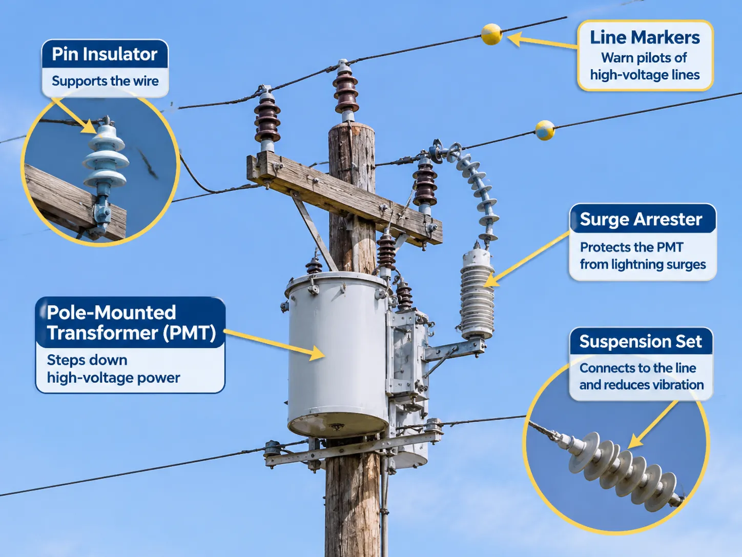
폴에 있는 둥근 것들의 정체
폴 마운트 변압기(PMT)는 일반적으로 폴 상단 부분에 위치합니다. PMT는 밀폐된 실린더 또는 탱크로 구성되며, 상단에 부싱이 장착되어 가공 전선과 연결됩니다. PMT는 절연체가 아니지만, 관찰하는 사람들에 의해 종종 절연체로 오인됩니다.
작은 둥근 물체인 핀 절연체는 PMT 옆의 크로스암에 위치하며, 디스크의 줄 모양 구성(“서스펜션 세트”)은 PMT와 배전선 사이의 연결 고리 역할을 합니다. 서지 아레스터(흰색 또는 회색 실린더로 PMT 옆에 장착됨)는 낙뢰 서지 및 전기선로를 따라 이동하는 관련 에너지로부터 PMT를 보호하도록 설계되었습니다.
스페이서 사이의 고전압 전선에 부착된 색상 마커는 조종사에게 항공기가 해당 선 근처를 비행하기 전에 허가를 받아야 함을 알리며, 서스펜션 지점의 링이나 작은 디스크는 진동을 줄이는 수단을 제공합니다.
구매자가 실제로 사용하는 용어와 그 중요성
이것은 조달 담당자들이 오해할 수도 있는데, 영어에서 “insulator”라는 단어가 세 가지 별개의 제품을 가리킬 수 있기 때문입니다. 누군가가 “33 kV 변전소용 절연체”를 요청할 때, 그들은 포스트 절연체, 서스펜션 디스크, 또는 부싱 중 어느 하나를 요청할 수 있으며, 이 세 가지 답변 모두 적절할 수 있습니다. 러시아어 용어 ввод는 부싱에 대한 올바른 용어이며, 영어로 절연체를 의미하는 изолятор와는 교환 가능하지 않습니다; 마찬가지로 중국어에서 套管은 부싱이고 绝缘子는 절연체입니다. 다국어로 작성된 명세서에서는 부품 번호와 도면이 용어보다 우선합니다.
구매 시, 다음 네 가지 항목을 명시하면 발생할 수 있는 혼란을 없앨 수 있습니다: 각 항목은 기능(통과/지지/서스펜션), 전기 절연 유형(전압 등급/절연 등급), 기계적 등급 및 해당 절연체 유형의 크리피지 거리(누설 거리)를 명시합니다. 이를 통해 공급업체는 자체적인 잘못된 라벨링에도 불구하고 적절한 제품을 정확히 견적할 수 있습니다.
재료: 자기질, 유리, 복합재, 에폭시, 종이
Porcelain is traditionally used; it is strong in compression; it remains stable/usable outdoors for decades, and its surface remains smooth and clean from deposits caused by pollution. The downside of porcelain insulators is that they are brittle and may break and not be visibly discernible until viewed from below. Tempered glass is generally used for suspension discs; however, it has a higher dielectric strength per millimetre than any other type of insulator and because it fails in a visible manner, it is easier to inspect, although it does come at an increased cost in both weight and the possibility of producing fragments upon failure.
Composite insulators are constructed of a fibreglass core with a silicone rubber shed. Porcelain and tempered glass electrical insulator materials have been the standard for years, but currently some manufacturers are offering composite type (silicone + FRP) electrical insulators which have many relative advantages over the previous two materials. Compared to porcelain and tempered glass, composite insulators are generally lighter in mass, provide better resistance to vandalism, operate satisfactorily in areas where airborne pollution is heavy, and typically composite insulators are manufactured with a hydrophobic (water repellent) coating on their outer surfaces. The hydrophobic coating is a factor in the performance of the composite insulator because while it provides some protection against moisture intrusion, it does not provide long term tracking resistance against moisture and UV radiation. The most significant issue affecting moisture and UVA tracking resistance in a composite insulator is the quality of the bond between the shed and the core. The bond quality can differ between manufacturers greatly. Epoxy cast resin is used to manufacture indoor switchgear bushings and post insulators, where the material can be cast to form a compact shape, while oil impregnated paper (OIP) is used within condenser bushing cores to control field grading between the coils and the OIP.
There are many types of materials currently available for use as the primary insulator in transmission and distribution electrical systems. As described earlier in this document, Porcelain, Tempered Glass and Composite Electrical Insulators are generally considered high strength materials with a high level of reliability. However, each material has both advantages and disadvantages as listed below.
| 재료 | Main use | 강도 | Weakness |
|---|---|---|---|
| Porcelain | post insulators, bushings | long life, stable surface | brittle, cracks hidden |
| Tempered glass | suspension discs | visible failure, high strength | weight, fragments |
| Composite (silicone + FRP) | transmission, polluted sites | light, hydrophobic, vandal resistant | bond quality varies |
| Epoxy cast resin | indoor switchgear | compact, precise shape | limited to indoor or protected |
| OIP paper | condenser bushing core | controlled field grading | moisture sensitive |
Creepage and why the number of discs matters
Creepage distance is the distance measured along an insulated surface from the live part (bus or conductor) to earth. Creepage distance is specified for each unit of line voltage. Each line voltage is different due to environmental conditions (pollution levels). Creepage distance is measured at the following values depending on pollution level at the site:
| Pollution level | Creepage distance |
|---|---|
| Light | 25 mm/kV |
| 중간 | 31 mm/kV |
| Heavy | 35–40 mm/kV |
The level of pollution (airborne) is determined by the environment and is not a personal preference of the Specification Writer. If a substation is located near a cement plant, in a coastal environment where it experiences exposure to salt spray, or in a location with a high concentration of conductive-type-dust; then you need the higher figure. The consequence for using an inappropriate number would be that you may have flashover during the foggy conditions rather than at the time of commissioning.
The meaning of this number is that it is also the reason that two insulators may be rated differently even though they are both the same height. The taller insulator has many more ribs, which will provide a longer creepage path compared to an insulator that is shorter and has widely spaced ribs that have been moulded deep into the insulator and have the appearance of being more robust. However, when the creepage path is analysed, the taller insulator has the higher creepage rating because it has a longer creepage path. The drawing provided in the standard gives the creepage percentage rating for each insulator, regardless of appearance.
Most of the packages used for substation equipment will have the same creepage requirement stated on the information sheet for each of the insulators used for that package, so that when the bills of material are created, they will list the packages based on pollution level, and then by voltage level, which is true for substation equipment within the same high voltage substation equipment range.
Where to buy, and what a set costs
There are three avenues to purchase these insulators and you cannot interchange them. The first one is from the original equipment manufacturer. When you are purchasing a bushing for a transformer, you purchase the bushing from the transformer manufacturer, and they guarantee that the bushing fits and that the field grading is correct. You can purchase the bushing separately from an existing transformer, but in that case, you are required to know the drawing, and the flange dimensions. The second group is the bushing and insulator component manufacturers; they each have a dedicated factory that manufactures these components and sells them direct to transformer manufacturers as well as electric utility companies. They can provide a spare set based on the original part’s drawing; this is typically the only way to acquire a replacement or upgraded version. The third type of manufacturer is the MRO distributor, which stocks common ratings of both bushings and insulators for immediate delivery at an extra cost of approximately 30% to 50% above standard pricing.
| 항목 | 전압 | Indicative price (USD) | 리드 타임 |
|---|---|---|---|
| Porcelain bushing, transformer | 12–24 kV | 60–250 each | 1–3 weeks |
| Composite bushing, transformer | 36 kV | 180–500 each | 2–4주 |
| Condenser OIP bushing | 145 kV | 4,000–18,000 each | 8–20주 |
| Post insulator | 12 kV | 30–120 each | 1–3 weeks |
| Suspension disc (70 kN class) | per unit | 6–25 each | 1–4 weeks |
| Corona ring | matching 145 kV | 150–600 each | supplied with the fitting |
These pricing indications are for budgetary purposes only and are not representative of what you would pay if you were to place a purchase order. The broad bands within the price ranges reflect the individual manufacturer’s cost to produce the insulators and bushings; there will be significant differences between an insulator supplied with only a Declaration of Conformity vs an insulator supplied with a full set of test documentation including routine test reports and type test certificates (the difference being approximately 20%-40% on average).
For orders in which insulators are included as part of an equipment package (e.g., in conjunction with other components such as transformers), it is more practical to purchase the insulators/insulator assemblies together as opposed to separately. By purchasing the assembly as a whole, it is much easier for the equipment designer/manufacturer to coordinate the interface of all of the components (the dimensions of the mounting flanges, creepage level, and corona ring) as opposed to each component having separate suppliers and potentially conflicting requirements; it is not uncommon for this to occur in the case of high voltage electrical equipment packages.
Manufacturers worth knowing
Three established names in insulator manufacturing are NGK Insulators (Japan), Sediver (France – glass) and Lapp Insulators (Germany – porcelain and composite). These companies comprise most of the global supply of transmission-class discs and posts and their catalogues serve as the reference for disc dimensions and mechanical class.
Trench Group is well respected as the manufacturer of bushings, while Hitachi Energy and ABB offer bushings as part of transformer and switchgear packages. The type-test documentation is what a utility specification usually cites for bushings. In many distribution-level projects, utilities will have two options: Either a regional factory that can supply an equivalent rating with a routine test report at a lower cost, or a classic global brand that has a longer history of field use. Both options are acceptable, and the deciding factor will be how the utility’s standard specification identifies a brand as an acceptable source. A mandated list will uniquely identify the source of supply.
When insulators are subcomponents of a transformer or switchgear order, the assembly supplier has responsibility for supply of the insulator(s), and the component range of insulators is provided under “Electrical Substation Components“.
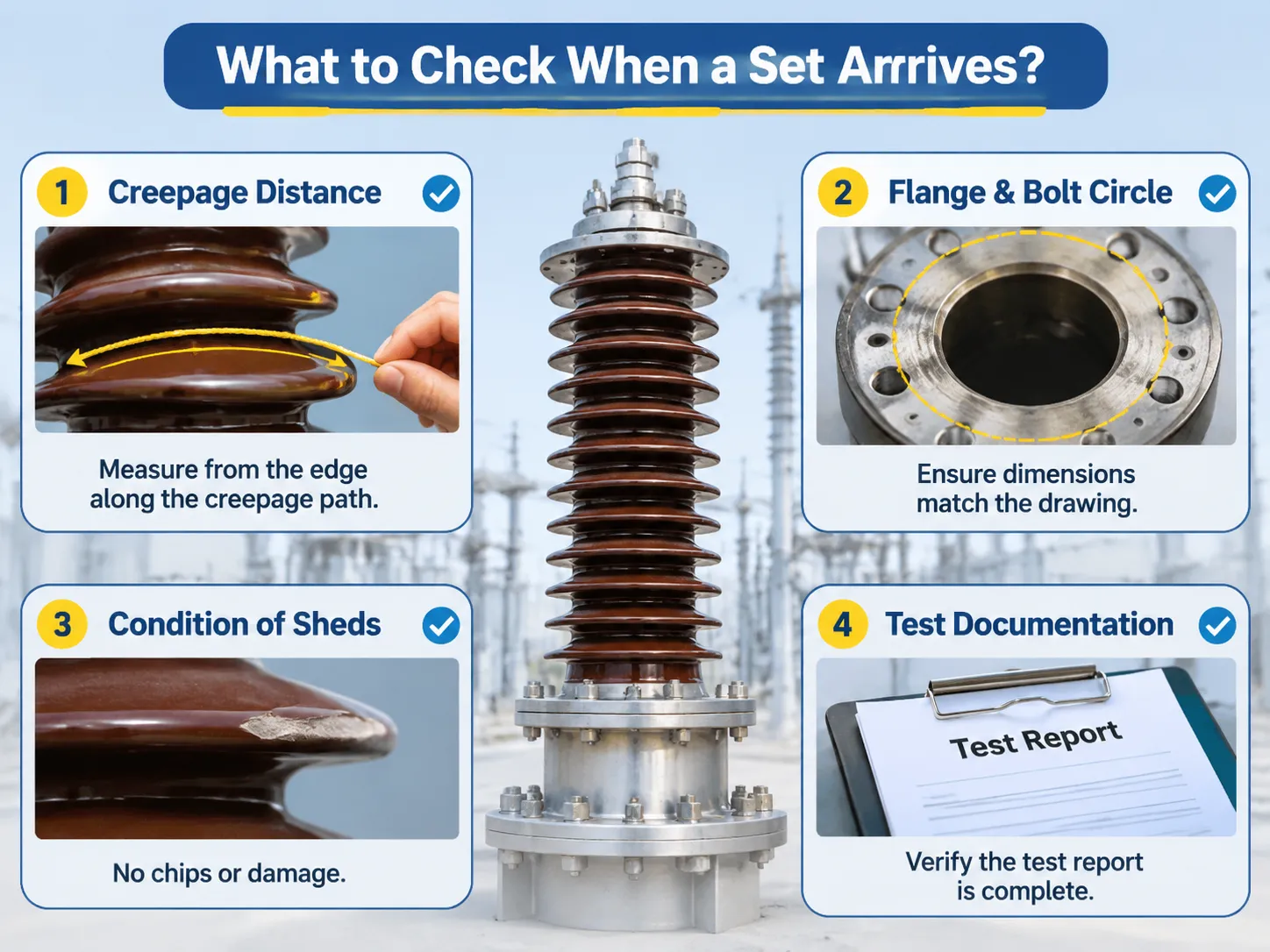
What to check when a set arrives
Four checks identify most issues, and none of these checks necessitate laboratory testing. The first check is the creepage distance compared to the drawing. Measuring the creepage distance is simply a matter of measuring from the edge of the insulator along the creepage distance with a piece of string, and even a creepage distance that is as little as ten percent short of what it should be, will cause the pollution class of the installation to be reduced.
Flange and bolt circle dimensions are the second most important aspect of bushing compatibility to the tank flange; if they do not match (i.e. are not the same), gaskets can not be installed and fluid can leak from the bushing to the tank. Condition of sheds is another critical aspect to the overall quality of the bushing. Chipped sheds on porcelain are not merely cosmetic; chips create a moisture trap and point where the electric field concentrates, which creates the potential for failure under most specifications. Test documentation is also crucial to bushing design. Normally, a unit test report is created for bushings; the type testing report provides the design-based information for the bushing and does not provide any testing information specific to the bushing. This same documentation logic applies to current transformers, whereas the numerous designs and schedules on the high-voltage current transformers document how the schedule of tests is attached to the individual unit and not to the batch of units it was tested with.
자주 묻는 질문
What are the round things on electric poles?
Typically, those are pole mounted transformers; they are sealed cylindrical tanks rather than insulators. The little circular objects on the crossarm just above the pole are pin insulators; the white cylinder that is bolted to the side of the transformer is a surge arrester that protects the transformer from lightning.
What are the types of insulators used in substations?
There are multiple styles of electrical insulators used in substations. These styles include post insulators for mounting bus bars, suspension insulators to support cables between towers, bushings to allow conductors to pass through grounded barriers, and enclosed apparatus insulators used within switched electrical gear and instrumentation transformers. Of these, the first three types tend to be visible and, therefore, will be what you see when looking at a substation from outside of the perimeter fence.
What are the circle things on power lines?
The circular coloured balls attached to high-voltage transmission lines are marker balls that warn pilots of the presence of the transmission lines below them. The smaller circular rings that fall within the anchor/support section of the transmission line serves as a vibration damper to help reduce the aeolian vibrations created by wind-induced movement. In contrast to those balls and rings, an insulator does not conduct electricity, so neither item should be mistaken for an insulator.
What does an insulator do in a substation?
Electrical insulators support live electrical components and separate them from energized portions of the operation and the ground as well as hold the electrical bus bars or overhead conductors in place; during normal operation, however, the insulator itself carries no current. The way an insulator works is determined primarily by the creepage distance, the mechanical load(es) and, depending on the use of the insulator as a long-term insulator, the levels of pollutants present in the environment.
Why is a bushing different from an insulator?
Yes, the primary distinction is that bushings hold conductor cables inside of them, whereas insulators do not carry current in any manner. This key difference between bushings and other forms of electricity-related tooling affects how bushings and other forms of electrical insulating products are designed, tested and, ultimately, how they fail when exposed to environmental conditions. Bushings fail when subjected to the presence of moisture and/or paper deterioration and by contrast, insulators fail primarily through surface flashover or mechanical breakage.
참고 문헌
- Trench Group — High Voltage Bushings and Coil Products
- NGK Insulators — Transmission and Substation Insulators
- Sediver — Toughened Glass Insulators
- Lapp Insulators — Porcelain and Composite Insulators
- Hitachi Energy — Bushings and Substation Equipment
결론
In conclusion, as we noted previously, the round or cylindrical items visible in the substations associated with electric utilities serve three distinct functions. First, as stated, bushings contain conductors travelling through the center of the bushing and serve the purpose of transferring electricity through themselves as normal insulators do. The next round object is the insulated supports; and lastly, the third reason round objects exist within substations relates to the corona rings and their role in shaping and forming the field surrounding the bushing; these do not touch anything.
As such, the importance of specifying the correct terminology associated with bushings (i.e., name, function, voltage class, mechanical rating and creepage distance) is paramount for determining the precise insulator components supplied when requested by the electrical utility customer.