


Todo engenheiro de produção já viveu uma tarde assim: uma linha de produção que não pode parar, uma onda de calor no verão e um transformador de subestação operando a 112 por cento da capacidade nominal porque não tem outra opção. A pergunta permanece a mesma: quem pode lhe dizer quanto de sobrecarga o transformador pode suportar e por quanto tempo, além de quanto isso custará em vida. A capacidade de sobrecarga não é um número imutável; em vez disso, é o resultado de inter-relações complexas – valores de carga anteriores, temperatura ambiente, temperatura do ponto mais quente, idade do isolamento e estado do sistema de refrigeração. Se você entender o sistema, pode operar eficientemente a 120-130 por cento de sobrecarga por horas durante emergências — ou queimar um transformador durante uma estação se negligenciar a ciência.
Em resumo, a capacidade de sobrecarga do transformador refere-se à capacidade de um transformador operar acima da capacidade especificada em sua placa de identificação por um determinado período. A limitação deriva da temperatura do ponto mais quente e do envelhecimento dos materiais isolantes, de acordo com a IEC 60076-7 e a IEEE C57.91. Na prática, um transformador que está em boas condições pode operar a 120% de sua capacidade nominal por várias horas. Existem situações de emergência em que ele pode operar com capacidade de 130-150% por um curto período.
O que é capacidade de sobrecarga de transformador?
A capacidade de sobrecarga do transformador refere-se à maior carga, além de seu valor nominal em MVA, que o transformador pode suportar por um período estabelecido sem ultrapassar os limites de temperatura que levariam ao envelhecimento rápido do isolamento. A capacidade de sobrecarga não é um número fixo, mas varia com o histórico de carga do transformador: um transformador operando a 40% de carga em uma noite fria tem o potencial de suportar uma sobrecarga muito maior do que aquele que já está operando a 95% durante a quente tarde. A capacidade nominal é apenas o valor máximo que o transformador pode fornecer sob carga total a uma temperatura nominal (tipicamente 40 °C, ocasionalmente até 55 °C em caso de designs não convencionais) e um valor de temperatura do ponto mais quente de 98 °C.
A questão é importante em termos econômicos, uma vez que as cargas normalmente não permanecem inalteradas. As empresas de energia e os usuários industriais frequentemente experimentam picos na faixa de 105-125% por horas ao dia, o que torna o conhecimento adequado sobre a capacidade de sobrecarga de um transformador indispensável para um operador qualificado. O uso do conhecimento apresentado acima para dimensionar cada transformador poderia levar a condições financeiras ruins: um transformador classificado para sua carga nominal pode operar a apenas 40% de carga por anos, consumindo perdas excessivas em vazio para se proteger de alguma sobrecarga ocorrendo por algumas horas mensalmente.
A Física: Temperatura do Ponto Mais Quente e Vida Útil do Isolamento
A questão pode ser expressa como um número: temperatura do ponto quente, a temperatura do enrolamento pode ser aumentada devido ao aquecimento I²R, causando um aumento na temperatura do óleo, enquanto a temperatura do ponto quente determina a taxa de envelhecimento do isolamento. A regra da indústria, especificada tanto na IEC 60076-7 quanto na IEEE C57.91, afirma que para isolamento de papel termicamente melhorado, a taxa de envelhecimento dobra a cada aumento de 6°C acima da temperatura de 98°C, a “regra dos 6°C”, algumas fontes até dizem que pode se aplicar a um intervalo de temperatura de 6°C a 10°C dependendo do tipo de material. Com a temperatura do ponto quente a 110 °C, a taxa de envelhecimento é de 4 a 8 vezes maior que o normal, enquanto com a temperatura do ponto quente de 130 °C pode ser de 30 a 100 vezes, o que significa que algumas horas a essa temperatura consomem vários meses de vida útil do isolamento.
A temperatura aumenta devido à carga, aproximadamente como o quadrado da corrente dividido pelo aumento da temperatura do enrolamento, mais o aumento mais lento da temperatura do óleo. Os refrigerantes — óleo e sistema de ventilador/radiador — determinam as constantes de tempo, então os modelos térmicos tratam a sobrecarga como um processo transitório com constantes de tempo de dezenas de minutos a horas. Um ponto mais importante é o fato de que a temperatura do ponto quente não é igual à temperatura do óleo superior. De fato, há um gradiente de temperatura entre o enrolamento e o óleo que geralmente é de 5 a 15K.
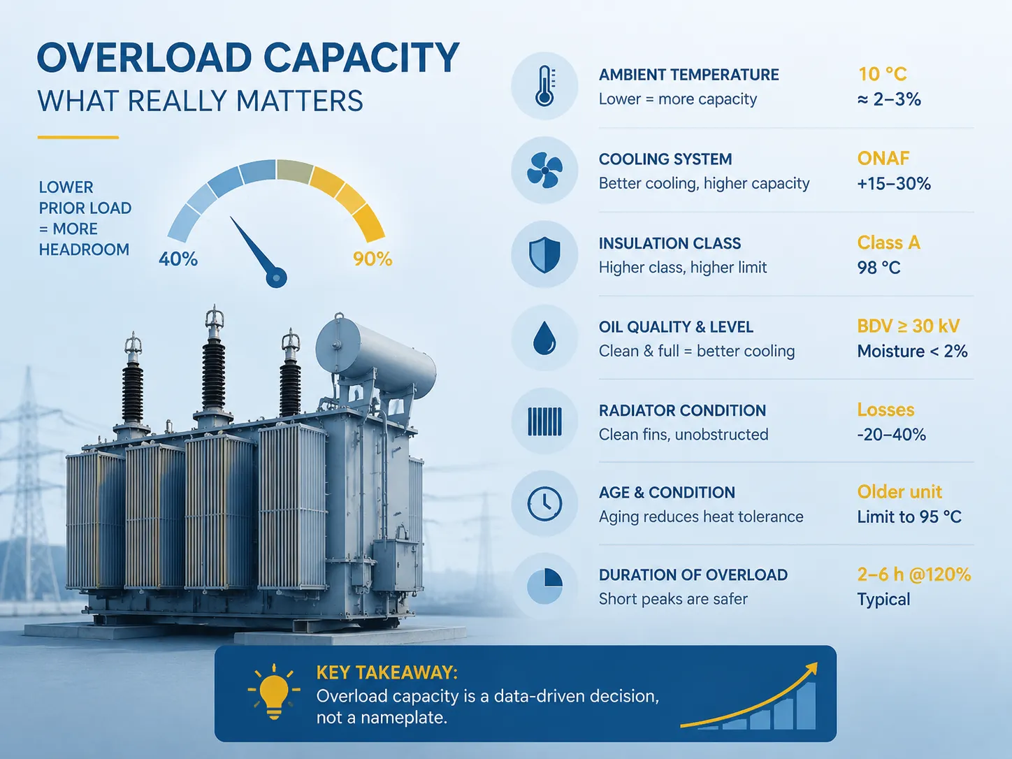
Fatores que determinam a capacidade de sobrecarga
| Fator | Efeito na capacidade de sobrecarga | Valores Típicos |
|---|---|---|
| Nível de carga anterior | Carga anterior mais baixa = mais reserva térmica | Carga anterior de 40% permite picos maiores do que 90% |
| Temperatura ambiente | Ambiente mais baixo adiciona espaço livre direto | Cada redução de 10 °C no ambiente adiciona aproximadamente 2–3% de capacidade |
| Sistema de resfriamento (ONAN/ONAF/ONAN→ONAF) | Ar/óleo forçado aumenta a dissipação de perdas | ONAF adiciona 15–30% de capacidade sobre ONAN |
| Classe de isolamento | Sistemas de classe superior toleram pontos quentes mais quentes | Classe A: 98 °C; aramida: classe 220 °C |
| Qualidade e nível do óleo | Óleo limpo e cheio dissipa calor melhor | BDV ≥ 30 kV, umidade < 2% |
| Condição do radiador | Fins bloqueados e poeira reduzem o resfriamento em 20–40% | Inspecione e limpe anualmente |
| Idade e condição do isolamento | Isolamento envelhecido tolera menos exposição ao ponto quente | Unidades mais antigas: reduzem o ponto quente permitido para 95 °C |
| Duração da sobrecarga | Picos curtos são baratos; sobrecargas sustentadas são caras | 2–6 h a 120% é típico; 120% sustentado degrada rapidamente |
Implicação na vida real: ao determinar a capacidade de sobrecarga, é melhor confiar nas informações apresentadas a você do que na placa de identificação. Um transformador eficiente, bem resfriado e levemente carregado pode ser operado por algumas horas a 130%. Por outro lado, um transformador velho e empoeirado, ou seja, um transformador que tem 30 anos e carregado a 90%, deve ser considerado como não tendo capacidade de sobrecarga alguma.
As Normas: IEC 60076-7 vs. IEEE C57.91
| Aspecto | IEC 60076-7 | IEEE C57.91 |
|---|---|---|
| Escopo | Guia de carregamento para transformadores de potência imersos em óleo | Guia para carregamento de transformadores imersos em óleo mineral |
| Princípio fundamental | Taxa de envelhecimento relativa vs. temperatura do ponto quente | Vida útil do isolamento consumida vs. exposição à temperatura |
| Ponto quente de referência | 98 °C para papel termicamente melhorado | 110 °C de referência “por unidade de vida” em muitas tabelas |
| Abordagem | Modelos térmicos simplificados e detalhados com fatores de carga | Modelo térmico completo, equações para óleo superior/inferior e enrolamento |
| Saídas | Tabelas e curvas de carga permissível vs. duração | Curvas de consumo de vida e carga para planejamento |
| Melhor utilizado por | Projetos europeus / internacionais | Empresas de serviços públicos e engenheiros de planejamento da América do Norte |
Os dois códigos chegam a conclusões de engenharia idênticas, mas as formulam de maneiras diferentes. A IEC 60076-7 fornece números diretos para carga cíclica; a IEEE C57.91 fornece fórmulas para modelagem térmica personalizada. É necessário saber que ambos os códigos existem, usar aquele que se adequa à área e ao contrato, e seguir o requisito chave comum a ambos os códigos, ou seja, a temperatura do ponto mais quente exposto deve estar de acordo com a vida útil de isolamento requerida.
Como Melhorar a Capacidade de Sobrecarga: 8 Métodos
| Método | Como Funciona | Ganho de Capacidade | Custo Típico |
|---|---|---|---|
| Adicionar ventiladores de resfriamento (ONAN→ONAF) | O ar forçado aumenta a dissipação do radiador | +15–30% | $2.000–$8.000 |
| Adicionar bombas de óleo (ONAF→OFAF) | A circulação forçada de óleo melhora a transferência de calor | +10–20% sobre ONAF | $5.000–$15.000 |
| Limpar radiadores e reparar o sistema de resfriamento | Restaura a dissipação de projeto | Restaura 20–40% de resfriamento perdido | $500–$3.000 |
| Adicionar ou aumentar radiadores | Mais área de superfície = mais rejeição de calor | +10–20% | $3.000–$12.000 |
| Instalar monitoramento de ponto mais quente / carga | Permite uso seguro e informado de sobrecarga | Permite uso total da capacidade real | $15.000–$45.000 |
| Controle automático de ventilador/bomba baseado em carga | O resfriamento funciona apenas quando necessário, protege o isolamento | Usa a capacidade disponível de forma precisa | $3.000–$8.000 |
| Sistema de isolamento de temperatura mais alta (aramida/éster) | Ponto mais quente permissível mais alto | +20–40 °C de folga no ponto quente | +20–40% (nova construção) |
| Ambiente reduzido / ventilação melhorada | Ar mais frio ao redor da unidade | ~2–3% por 10 °C | Específico para o local |
As abordagens de menor custo são o primeiro passo: processos simples como limpeza de radiadores, reparo de ventiladores e verificações regulares do nível de óleo podem restaurar até 20-40% de resfriamento perdido por menos de $3,000. Outro passo adiante seria o uso de ventiladores e bombas adicionais, mantendo os investimentos modestos. No entanto, o próprio processo de monitoramento não pode aumentar a capacidade, ele pode apenas torná-la possível.
Mantendo o Sistema Estável Sob Sobrecarga
A capacidade de sobrecarga provará ser eficiente apenas se o sistema for capaz de funcionar corretamente sob estresse encontrado. O ponto mais significativo é a regulação de tensão: quanto mais carregado o transformador estiver, mais tensão ele perderá, portanto, quando o transformador opera a 125% da potência nominal, ele pode se encontrar na situação em que a tensão a jusante será menor do que a permitida, especificamente no final de longas alimentações. Verifique a configuração do tap e considere a ideia de usar regulação automática de tensão. Na maioria das instâncias, há uma queda de 5% na tensão no ponto de acoplamento comum, após a qual haverá uma desvio no funcionamento da carga. O segundo ponto é a coordenação de proteção: as configurações do relé e as características do relé de sobrecarga devem possibilitar que seja carregado excessivamente sem desconectar da rede, no entanto, ainda deve operar em caso de falhas. Revise a curva do relé em relação à curva do limite térmico do transformador para entender o que permanece abaixo do dano enquanto ainda está sob condições de segurança. O terceiro ponto é a distribuição de carga: na operação em paralelo de transformadores, um deles funcionará de forma menos eficiente devido a uma grande diferença nas impedâncias.
Em conclusão, a confiabilidade do resfriamento, em tempos de sobrecarga, é extremamente significativa em termos de segurança. O resfriamento forçado e o resfriamento de óleo forçado são cargas na potência auxiliar do local, e em caso de falha da potência auxiliar em horários de pico, o transformador desligará os ventiladores e bombas no momento da necessidade.
| Prática de Estabilidade | O que Prevê | Custo Típico | Prioridade |
|---|---|---|---|
| Revise as curvas do relé vs. curva do limite térmico | Desconexões indesejadas e falhas não detectadas | Tempo de engenharia | Alto |
| Verificação da queda de tensão a 125% de carga | Subtensão em cargas a jusante | Estudo de fluxo de carga | Alto |
| Correção de impedância/tap de transformador em paralelo | Compartilhamento desigual de carga, uma unidade sobrecarregada | $500–$3.000 | Médio |
| Fonte auxiliar alimentada de forma dupla / com backup | Perda de ventiladores/bombas durante o pico | $2.000–$15.000 | Médio |
| Descarregamento automático de carga em falha de resfriamento | Danos à isolação devido a sobrecarga não resfriada | $3.000–$8.000 | Alto |
| Transferência de carga / deslocamento de pico | Sobrecarga sustentada acima da janela nominal | Operacional, baixo | Alto |
Aplicações: Quando a Capacidade de Sobrecarga Realmente Importa
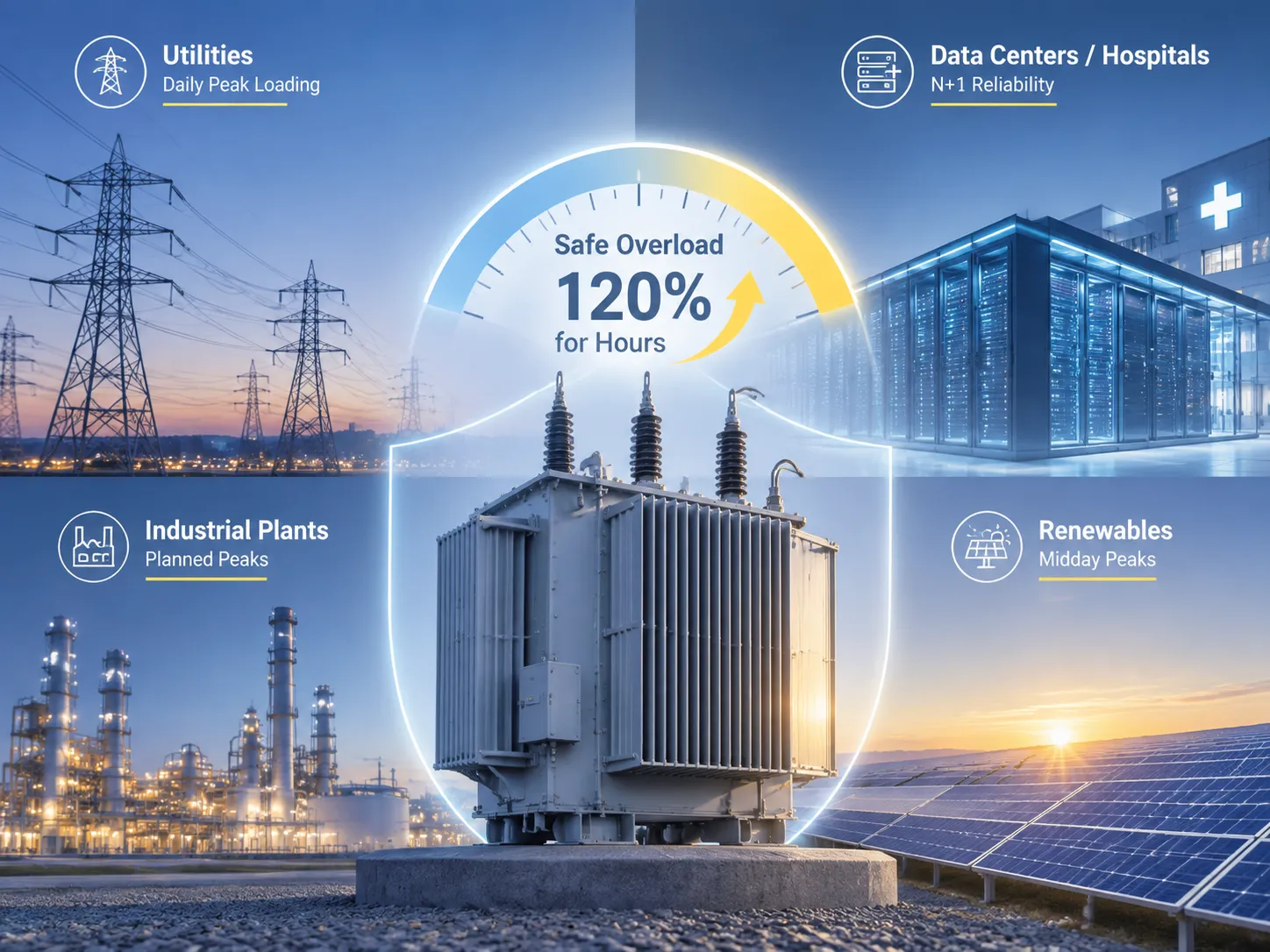
Várias indústrias utilizam a capacidade de sobrecarga de maneiras diferentes. O setor de utilidades emprega ciclos diariamente; transformadores de distribuição normalmente consideram a carga máxima diariamente, e a prática de conseguir operar a 120% de capacidade por duas a três horas durante o pico de carga da noite sem comprometer o transformador é bem conhecida. Indústrias de processos em lote têm picos regulares de demanda, como quando um forno é iniciado ou uma máquina é ligada – para esses processos, sobrecargas curtas são possíveis desde que a capacidade térmica da instalação seja compreendida. Por outro lado, hospitais e centros de dados trabalham com o conceito N+1, o que significa que a sobrecarga do transformador é evitada em circunstâncias normais, embora, quando a energia é alternada entre diferentes transformadores, o processo de transferência crie condições temporárias de sobrecarga nos transformadores, e essa capacidade de sobrecarga é considerada uma vantagem de segurança no processo. O conceito de fontes de energia renováveis traz novos desafios também, com sistemas de energia solar criando sobrecarga durante os picos de meio-dia e subcarga à noite, enquanto o ciclo térmico em si contribui para cargas mecânicas nos transformadores – atualmente, a técnica utilizada é isolamento de alta qualidade e monitoramento.
Em todos os casos, o algoritmo é o mesmo: entender as características da curva de duração da carga; calcular a carga máxima no ponto mais quente; descobrir a condição de isolamento da unidade – dessa forma, tabelas de sobrecarga ou um modelo térmico ajudarão a entender qual nível é aceitável e seguro.
Equipamentos, Fornecedores e Faixas de Preço
| Equipamento / Serviço | Fornecedores Representativos | Faixa de Preço Típica | Observações |
|---|---|---|---|
| Ventiladores de resfriamento de radiador e controles | Kelvion, Plexus, OEMs locais | $2,000–$8,000 por transformador | Inclui ventiladores motorizados e contatores |
| Bombas de óleo (circulação forçada de óleo) | Kelvion, OEMs locais | $5.000–$15.000 | Para conversões OFAF/ODAF |
| Monitores de temperatura de enrolamento online / ponto mais quente | Qualitrol, Doble, Maschinenfabrik Reinhausen (MR) | $15.000–$45.000 | Fibra óptica ou baseada em modelo |
| Relés de monitoramento e controle de carga | Schneider Electric, ABB, GE | $1.500–$6.000 | Funções de alarme/controle de sobrecarga |
| Transformadores de alta classe de óleo éster / aramida | Hitachi Energy, Siemens Energy, Jiangsu Subian Electric Power | $25,000–$60,000 (classe de 2,000 kVA) | Isolamento premium para serviço de sobrecarga |
Os preços dependem das especificações e regiões, portanto, use-os como valores de referência. As marcas mundialmente famosas — Qualitrol e MR para monitoramento, Kelvion para resfriamento e Schneider/ABB para controles — estabelecem o padrão e esses preços refletem esse fato. Os usuários finais podem comprar transformadores produzidos para aplicações de alta sobrecarga (com resfriamento aprimorado, isolamento de classe mundial e margens de projeto máximas) de empresas como Jiangsu Subian Electric Power que cumprem com a IEC 60076 e projetam transformadores de distribuição e potência de alta qualidade com sistemas de resfriamento e isolamento adequados para processos pesados — o preço pode ser conhecido e diferir de 20% a 40% da média europeia. Independentemente do que está sendo adquirido, a especificação deve conter informações sobre o perfil de carga cíclica para que o fabricante possa incorporar esses dados no cálculo da margem de resfriamento e isolamento qualitativo.
Perguntas Frequentes
Quanto de sobrecarga um transformador pode suportar com segurança?
A capacidade máxima que um transformador pode suportar varia dependendo de muitos fatores, como a carga nominal, aquecimento, resfriamento e outros fatores. No entanto, como regra geral, um transformador típico classificado como ONAN pode operar normalmente em 120-130% da capacidade nominal por duas a seis horas em condições normais. No caso de transformadores com resfriamento a ar (ONAF), eles têm 15-30% de capacidade adicional. Em média, a limitação está na temperatura do ponto mais quente, que não deve ser superior a 110 °C.
O que a sobrecarga faz com a vida útil do isolamento do transformador?
De acordo com a “regra dos 6 graus”, a vida útil do isolamento de transformadores feitos de papel termicamente aprimorado pode ser calculada, pois a vida útil do isolamento dobra para cada seis graus acima da temperatura nominal (de 98 °C). Se a temperatura subir para 110 °C, a vida útil do isolamento será de 4 a 8 vezes a de 98 °C e a 130 °C – de 30 a 100 vezes. Nesse caso, a sobrecarga moderada não terá efeito na vida do transformador, mas uma sobrecarga severa consumirá sua vida.
Posso adicionar resfriamento a um transformador existente para melhorar a capacidade de sobrecarga?
Normalmente, sim. Esta é uma solução econômica que pode aumentar a capacidade do transformador mudando seu sistema de resfriamento de ONAN para ONAF ou limpando os radiadores bloqueados e reparando as unidades de resfriamento por ventilador. Outras opções são a instalação de um sistema de resfriamento a óleo (OFAF). É importante esclarecer as especificações do transformador e conformar as modificações do ponto de vista técnico antes de introduzir quaisquer mudanças no sistema de resfriamento.
Qual é a diferença entre resfriamento ONAN, ONAF e OFAF?
A diferença entre ONAN, ONAF e OFAF é que eles são designações de resfriamento da IEC. ONAN cria resfriamento natural com óleo circulando em um transformador; ONAF adiciona resfriamento artificial com ar e OFAF fornece resfriamento forçado com óleo. Quanto maior a classe de resfriamento atribuída ao transformador, maior a capacidade em watts que ele alcança.
Devo dimensionar um transformador para carga de pico ou carga média?
É um erro se preocupar principalmente com uma dessas abordagens. Primeiro, é importante concluir até que ponto a carga média pode ser permitida em vista da quantidade de perdas de tensão geradas pelo transformador. Por exemplo, ao tentar identificar a carga média, deve-se notar que mesmo que um transformador opere com carga média, ele ainda pode consumir a tensão máxima em momentos específicos. Para a identificação confiável da estratégia operacional, é aconselhável usar ferramentas mais avançadas, como normas regulatórias IEC.
Referências
- IEC 60076-7: Transformadores de potência – Parte 7: Guia de carga para transformadores de potência imersos em óleo — a norma internacional para avaliação de carga permissível e sobrecarga cíclica.
- IEEE C57.91: Guia para Carga de Transformadores Imersos em Óleo Mineral — o guia de carga da América do Norte com modelos térmicos e métodos de consumo de vida.
- IEC 60076-2: Transformadores de potência – Parte 2: Aumento de temperatura — define limites de aumento de temperatura que delimitam a capacidade de sobrecarga.
- IEEE C57.140: Avaliação e Recondicionamento de Transformadores de Potência Imersos em Líquido — metodologia de consumo de vida para decisões de carga baseadas em condição.
- IEC 60156: Tensão de ruptura de líquidos isolantes — teste de condição do óleo relevante para a integridade térmica e elétrica durante sobrecarga.
- Fábrica de Máquinas Reinhausen (MR) — fornecedor de comutadores de tap on-load e equipamentos de monitoramento para operação de transformadores carregados.
- Jiangsu Subian Electric Power — fabricante de transformadores em conformidade com IEC 60076 que oferece opções de resfriamento e isolamento aprimoradas para serviço cíclico pesado.
Conclusão
Recurso real e quantificável, a capacidade de sobrecarga do transformador é um recurso amplamente subutilizado pelos operadores, uma vez que não conseguem identificar a temperatura do ponto mais quente. A ciência por trás disso é simples: a sobrecarga é limitada pela vida do isolamento que se reduz pela metade a cada aumento de 6 °C a partir da temperatura do ponto mais quente de 98 °C. A tecnologia está disponível: diretrizes e normas de carregamento IEC 60076-7 e IEEE C57.91; atualização do sistema de resfriamento, isolamento de maior qualidade e sistemas de monitoramento remoto. O lado econômico do problema favorece a utilização informada: gastar $2.000–$8.000 em ventiladores de resfriamento e $15.000–$45.000 no sistema de monitoramento remoto pode ajudar a evitar uma despesa de $50.000–$500.000 na compra de transformadores.
- É a temperatura do ponto mais quente que determina quanta capacidade de resfriamento o transformador pode suportar.
- Limpe os radiadores e repare os sistemas de resfriamento primeiro — é a maneira mais barata de aumentar a capacidade.
- A conversão de ONAN→ONAF fornece uma capacidade adicional de 15–30% para $2.000–$8.000.
- Use as tabelas e modelos IEC 60076-7 / IEEE C57.91 antes de considerar sobrecarga.
- Monitore a temperatura do ponto mais quente de transformadores cruciais e mantenha o fornecimento de resfriamento auxiliar firme.
- Defina o perfil de carga cíclica com antecedência — Jiangsu Subian Electric Power fabrica unidades em conformidade com a norma IEC.