


Когда вы запрашиваете информацию о зазорах вокруг трансформатора, обычно возникает первоначальный вопрос, который ведет к трем последующим вопросам. При рассмотрении того, сколько рабочего пространства доступно вокруг оборудования, необходимо учитывать следующее: сколько пространства требуется перед оборудованием для создания безопасной рабочей среды для оператора? Какой тип зазора необходим для защиты от пожароопасных факторов на основе горючего конструкционного материала, который может контактировать с оборудованием? И, наконец, как производитель обеспечивает адекватный воздушный поток для охлаждения оборудования и минимизации риска отказа оборудования? Каждая из этих трех областей определяется NEC в отдельных статьях, требует разного метода измерения, и максимальный размер либо перед, вокруг, либо между двумя единицами оборудования определяет расположение оборудования.
Быстрый ответ: Рабочее пространство, необходимое для обслуживания трансформатора, указано в NEC 110.26, который устанавливает требуемые размеры рабочего пространства для оборудования с напряжением до 150 вольт, которое должно иметь не менее 900 мм перед трансформатором, а оборудование с напряжением от 151 до 600 вольт должно располагаться на расстоянии не менее 900 мм от трансформатора и до 1200 мм в зависимости от того, что находится с противоположной стороны трансформатора. Сухие трансформаторы с мощностью более 112,5 кВА и установленными внутри помещений должны размещаться в огнестойком помещении, как определено в NEC 450.21. Трансформаторы с масляной изоляцией, если установлены внутри, должны размещаться в огнестойком хранилище, как определено в NEC 450.26, если только они не используют сертифицированную огнестойкую жидкость. Маслонаполненные трансформаторы, установленные снаружи, должны находиться на расстоянии не менее трех метров от любой стены, окна или двери, связанных с горючим зданием, если не предусмотрен противопожарный барьер, который позволяет размещать трансформатор ближе к горючему зданию. Зазор для воздушного потока обычно составляет от 150 до 300 мм, в зависимости от конкретного типа производимого трансформатора, и является дополнительным требованием, не заменяющим другие перечисленные выше требования.
Ниже приведены разделы, которые разбивают и суммируют три отдельных типа требований к зазорам, показывают таблицу требуемого рабочего пространства по напряжению, описывают правило для сухих помещений и правило для масляных хранилищ, описывают требуемое наружное расстояние между трансформаторами и горючими материалами, детализируют требования к вентиляционным зазорам, где трансформаторы должны быть доступны для обслуживания, как трансформаторы должны быть идентифицированы, выделяют ключевые различия между Канадой и Соединенными Штатами, суммируют по типу зазора и рейтингу, а также что должно быть показано на чертеже расположения.
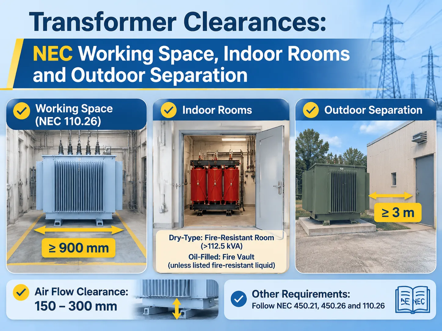
Три вида зазоров и почему их путают
Существует три типа зазоров, и часто их путают.
Этот рабочее пространство речь идет о людях, и это пространство перед оборудованием, которое должно оставаться свободным, чтобы квалифицированное лицо могло получить к нему доступ, выполнить измерение и покинуть его. Рабочее пространство определяется напряжением, присутствующим на передней части оборудования, а также током, протекающим к оборудованию. Все это можно измерить с помощью измерительных лент и оно должно соответствовать спецификациям во время инспекции.
Когда мы говорим о противопожарных разделениях, мы имеем в виду здание. Расстояния противопожарного разделения включают все расстояния/конструкции, которые отделяют распространение огня от трансформатора от горючих материалов или от трансформатора к любым другим поверхностям в помещении. Расстояния противопожарного разделения представлены либо в метрах, либо в виде показателя огнестойкости помещения. В любом случае они основаны на том, содержит ли трансформатор масло.
Вентиляционные зазоры в первую очередь касаются оборудования. Сухой трансформатор генерирует тепло из-за потерь в обмотках трансформатора, и все, что блокирует прохладный поток воздуха над обмотками трансформатора, приведет к повышению температуры обмоток трансформатора, сокращению срока службы изоляции и в конечном итоге к отключению трансформатора по тепловой защите. Вентиляционные зазоры определяются исключительно из инструкций по установке производителя, которые являются обязательными к соблюдению, и часто определяют планировку помещения.
Таким образом, между рабочим пространством, противопожарным разделением и вентиляционными зазорами люди путают их, потому что все они называются зазором, но только один из них содержится в справочной таблице для монтажников. Следовательно, любое помещение, где планировка соответствует требованиям рабочего пространства (110.26) национального электрического кодекса, но не соответствует вентиляционным зазорам, будет инспектироваться и эксплуатироваться в условиях, вызывающих перегрев. С другой стороны, планировка, которая соответствует вентиляционным зазорам, но не соответствует требованию рабочего пространства (110.26), будет инспектироваться и принята с холодным трансформатором.
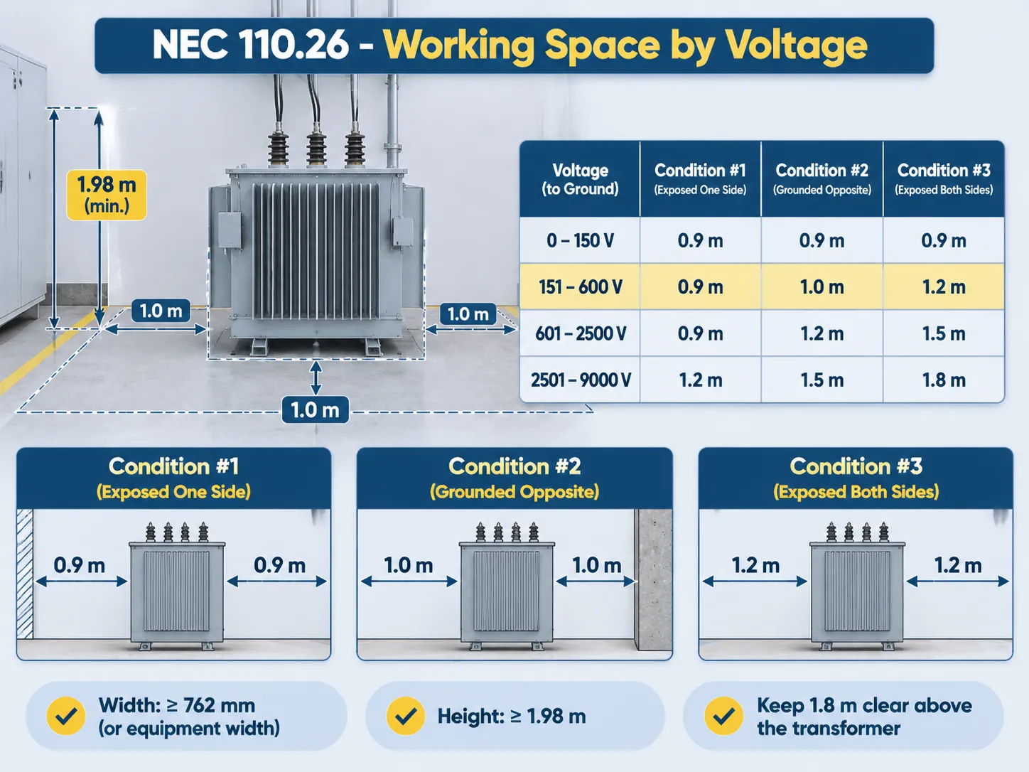
Рабочее пространство согласно NEC 110.26, по напряжению
Рабочее пространство, как определено в NEC 110.26, может быть рассчитано на основе размера установки и расстояния от токоведущих частей.
Измерения расстояний, требуемые для каждого напряжения до земли, и требования к рабочему пространству варьируются в зависимости от типа корпуса, определенного в NEC: (1) Условие #1 – Открытые токоведущие части с одной стороны и отсутствуют другие токоведущие или заземленные корпуса с противоположной стороны. (2) Условие #2 – Открытые токоведущие части с одной стороны и заземленные части (например, бетон или кладка) с противоположной стороны. (3) Условие #3 – Открытые токоведущие части с обеих сторон корпуса.
| Напряжение (до земли) | Условие #1 | Условие #2 | Условие #3 |
|---|---|---|---|
| 0-150 В | 900 мм | 900 мм | 900 мм |
| 151 – 600 В | 900 мм | 1,0 м | 1,2 м |
| 601 – 2500 В | 900 мм | 1,2 м | 1,5 м |
| 2501 – 9000 В | 1,2 м | 1,5 м | 1,8 м |
Большинство низковольтных трансформаторов, около 151 до 600 вольт, подпадают под Условие #2 с эффективная ширина рабочего пространства 1,0 метр вместо разрешённой ширины 900 мм для условия #1. Первичная обмотка на 480 вольт с вторичной обмоткой на 208 вольт считается установкой на 480 вольт для размеров рабочего пространства. Требование условия #2 применяется, когда спина электрика находится у кирпичной или бетонной стены.
В дополнение к требованиям по ширине и глубине рабочего пространства, три дополнительных размера завершают размеры рабочего пространства, указанные в NEC 110.26:
Ширина рабочего пространства — минимальное расстояние 762 мм или больше ширины оборудования (в зависимости от того, что больше). Высота рабочего пространства — минимум 1,98 м. Рабочее пространство должно быть предназначено только для работы; то есть ничего не должно устанавливаться или крепиться к оборудованию в радиусе 1,8 м. Последнее требование запрещает установку любых кабельных лотков непосредственно над трансформатором. Это часто встречается в машинных залах, где планировка оборудования была установлена до того, как это правило стало применяться последовательно.
Это требование также применяется к полностью закрытым трансформаторам, поскольку рабочее пространство необходимо для оборудования, установленного рядом с ними. Хотя полностью закрытый блок может не иметь открытых токоведущих частей, внутри отсека всё равно находятся клеммы, к которым необходимо иметь доступ при установке и обслуживании. Кодекс признаёт необходимость рабочего пространства вокруг трансформатора независимо от того, полностью ли он закрыт.
Сухой тип для помещений: Правило 450.21 о помещении
Любой сухой трансформатор мощностью более 112,5 кВА, установленный в помещении, должен размещаться в трансформаторном помещении , которое построено в соответствии с требованиями огнестойкого строительства и изолировано от остальной части здания стенами, полами и потолками с заданными огнестойкими характеристиками. Трансформаторы мощностью ниже 112,5 кВА не имеют таких требований к огнестойкости, поэтому многие малые трансформаторы размещаются в шкафу и не имеют огнестойкого корпуса.
Существует конкретное исключение из этого требования, которое применяется к очень узкой группе проектов. Трансформатор с изоляцией класса 155 или выше, отделённый от горючих материалов огнестойким барьером, может быть установлен вне выделенного трансформаторного помещения. Главное условие — огнестойкий барьер должен быть выполнен в виде сплошной стены со всех четырёх сторон трансформатора, отделяющей его от горючих материалов.
Важно понимать пороговый рейтинг как фактор проектирования при установке трансформатора в помещении или на улице.
Размер 112,5 кВА считается малым коммерческим трансформатором, а следующий уровень — 150 кВА — потребует не только более крупного кабеля, но и большего помещения для его размещения. Трансформаторы, проектируемые на поздних этапах строительства, могут создавать сложности. Например, если проект подрядчика изменяется с трансформатора 112,5 кВА на 150 кВА, возможно, потребуется добавить дополнительное пространство для этого трансформатора во время строительства.
При проектировании помещений для трансформаторов с литой изоляцией и системой охлаждения требования к системе охлаждения будут определять окончательную планировку трансформаторного помещения. Для обеспечения достаточной вентиляции литых трансформаторов требуется дополнительный зазор от 150 мм до 300 мм с каждой стороны трансформатора. Кроме того, трансформаторные помещения должны иметь входные и выходные отверстия воздуховодов, рассчитанные на общую тепловую нагрузку, а не на каждый отдельный трансформатор. Наши коммерческие запросы по сухим трансформаторам для внутреннего размещения почти исключительно основаны на трансформаторе 10 кВ серии SCBH. Требования к установке трансформаторов SCBH можно найти в технической документации. Требования к зазорам с каждой стороны трансформатора включены в документацию, поэтому подрядчику не нужно гадать или делать предположения относительно требований к зазорам.
Маслонаполненные трансформаторы для внутреннего размещения: камеры и исключение для менее горючих жидкостей
Маслонаполненный трансформатор для внутреннего размещения должен быть установлен в масляной камере. Камера должна соответствовать дополнительным стандартам, таким как огнестойкость, удержание жидкости, дренаж и вентиляция, чтобы выполнять свои функции. В случае маслонаполненного трансформатора опасность пожара связана с возможным образованием большого количества горячих газов, которые могут выделяться самим трансформатором, а также с утечкой масла, которая может произойти при выходе трансформатора из строя.
Еще одним изменением на рынке трансформаторов является доступность менее горючей жидкости.
NEC 450.23 допускает внутреннюю установку трансформатора с негорючей жидкостью по сертифицированному методу при условии соблюдения минимального расстояния от горючих материалов и наличия адекватной автоматической системы пожаротушения для крупных установок. Эти жидкости на основе эфиров, как натуральные, так и синтетические, в последние годы широко применяются в проектах; таким образом, маслонаполненный трансформатор для внутреннего размещения стал стандартом, а не специализированным оборудованием.
Для получения исключения по этой жидкости должны быть выполнены четыре условия: (a) она должна быть сертифицирована как менее горючая, (b) сертификат должен быть конкретно для этой жидкости, а не для семейства жидкостей, (c) должно быть разделение, обычно расстояние 3 м от горючих материалов или огнестойкий барьер, (d) уровень пожарной защиты должен соответствовать требованиям сертификата; для малых трансформаторов ничего не требуется, а для крупных трансформаторов необходима система подавления.
В общем, проекты с использованием минерального масла потребуют наличия камеры, а вентиляция камеры также должна быть предусмотрена в конструкции камеры. Камера должна иметь как входное, так и выходное отверстие, рассчитанные на тепловые потери, а также адекватную защиту от дождя и проникновения животных. Если проект расположен в жарком климате, температура в камере в какой-то момент ограничит мощность трансформатора; поэтому стоит как можно раньше сообщить об этом архитектору. The 20 kV oil immersed distribution transformer is the most common transformer discussed when discussing this subject with the architect and including the specifications of the transformer fluid as part of our proposal is imperative.
Outdoor Separation: The 3 m Rule and Fire Barriers
Protecting the area around the transformer with a sufficient distance from combustible materials outside of buildings provides a reasonable amount of fire separation.
Distance is measured from the boundaries of the transformer enclosure, but the distance remains regardless of the position of any combustible materials near the building. A pad mounted permanently on or over a combustible architectural element is a violation unless that architectural element has been classified as either a fire barrier or has an acceptable fire rating.
The location of the transformer enclosure will affect the layout of the transformer site on an overall site basis.
Three other elements that relate to the distance between the transformer enclosure and the nearest point of combustible construction are:
- The bund or plinth must direct any liquid spill from the transformer enclosure away from the nearest building and away from any storm drain.
- Access must be maintained to allow installation, maintenance, or replacement of the enclosure.
- Security requirements to secure the enclosure against unauthorized entry into public areas require that the enclosure have a locking device that can be opened by the utility.
Этот pad-mounted transformer enclosure is where the intersection of the above listed elements meets. This may explain why pad-mounted transformers have set back requirements, while substations constructed off-site in a prefabricated unit are considered as separate buildings requiring their own set of fire strategies.
The Air Circulation and Ventilation Requirements Indicated by the Manufacturer
The air circulation is the primary method of cooling a dry-type transformer, which is common in commercial environments. Since dry-type transformers depend on moving air to cool them, the evaporating surfaces are always located completely exposed with no obstructions. The ventilation face surfaces must maintain a minimum clearance of between 150-300 mm (6-12 inches) from any obstructing objects; if the dry-type transformer has a higher rated capacity (greater than 1000 kVA) or has been installed with an acoustic enclosure, the clearances must be even greater than the 150-300 mm (6-12 inches) recommended.
When looking at the ventilation and cooling of a dry-type transformer, it is important to look at not only the transformer, but also the room that houses it. Dry-type transformers can reject many kilowatts (kW) of heat. If the transformer is in a completely sealed enclosure, the ambient temperature in the room will ultimately be at a level where the transformer will derate. Therefore, it is extremely important that when designing a room, that the appropriate amount of inlet and outlet area is calculated for the transformer rating being installed; a room designed for a 500 kVA transformer cannot have a 1000 kVA transformer installed in it without proper ventilation and cooling capabilities.
Sound is also another important factor in the design of a dry-type transformer installation. If a transformer is located very close to a solid wall, the sound from the transformer will reflect off the wall and cause an increase in perceived sound levels; this can cause complaints in a manufacturing environment. Therefore, moving a transformer at least 300 mm (12 inches) away from the wall at the design phase is cost-effective, but making this change at a later date can be very costly.
Accessibility, Disconnection and Dedicated Space
The three basic features of dry-type transformer design, aside from dimensions, are very often overlooked: access to qualified personnel; how to safely and effectively disconnect the transformer; and the amount of dedicated space required. Although a dry-type transformer must be accessible to qualified personnel, installing the transformer above a ceiling is only acceptable if the qualified personnel can access the transformer without having to remove the building finish.
To ensure a safe work environment for electricians, there must be a disconnection device located within sight of the electrical equipment. If it cannot be seen, then it must have a way to prevent it from being re-energized (that is, a lockable device). In addition, working space requirements are specific and must be maintained; therefore, no items such as ladders, boxes, spare pumps, etc., should be placed in front of the equipment that requires a dedicated work area.
The accessibility requirement has application to dry-type transformers. The Canadian Electric Code (CEC) has issued the following: Where a dry-type transformer is installed in a ceiling void and can be accessed via an access panel, and the transformer has a rating below the established limit, the CEC allows an approved small transformer. However, if a transformer requires a ladder for installation and/or requires removal of ceiling tile as part of the installation process, it is considered a maintenance issue rather than an approved installation.
Canada: CEC Rule 2-308 and Where It Differs
Canada is also governed by the Canadian Electrical Code (CEC), Section 2-308 2, and Rule 2-308 identifies the requirements for working space surrounding electrical equipment. The working space surrounding electrical equipment must have a minimum height of 2 meters, a width that is equal to the size of the electrical equipment; or 750mm; and a depth that is at least 1 meter in front of the equipment. The numbers stated above agree with the NEC numbers, but the structure is different; CEC has one working space number “1 meter” rather than use a table similar to the NEC to categorize working space by the voltage and condition; therefore the Canadian requirements are simpler to use and slightly more restrictive at low voltages.
Transformers are covered in Section 26 of the Canadian Electrical Code. The fire separation of the transformers is similar to the fire separation for other electrical equipment; the fire separation of dry-type transformers above a certain rating require the dry-type transformer to be installed in a fire-rated room or a fire-separation location; likewise, oil-filled transformers must be installed in vaults and have their own fire separation from combustible construction if installed outdoors.
Each province has its own amendments. Therefore, some projects will be subjected to more demanding standards/requirements from local jurisdictions in provinces/states than the model code.
For projects that cross the province/state line, the practical approach is to design for the most stringent of the two forms and keep a record of which one you used to create your project. The layouts meeting both sets of requirements are seldom costlier than those meeting only the NEC, since the only difference in the depths between the two is typically 100 mm.
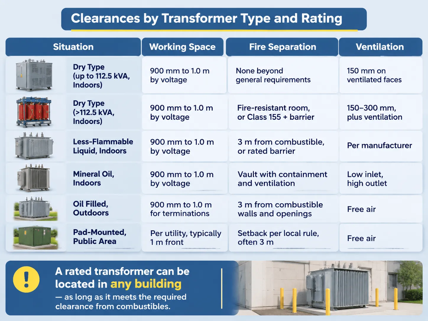
Clearances by Transformer Type and Rating
The information contained in the table is a summation of the information that appears on the drawings, and it is not intended to substitute for the text of the code if your project has local amendments, you still are held to the local provisions.
Type of transformer and location. Range of ratings and sizes of rated transformers will differ due to use. Fire resistance is a function of building design.
| Ситуация | Working space | Fire separation | Вентиляция |
|---|---|---|---|
| Dry type up to 112.5 kVA, indoors | 900 mm to 1.0 m by voltage | None beyond general building requirements | 150 mm on ventilated faces |
| Dry type above 112.5 kVA, indoors | 900 mm to 1.0 m by voltage | Fire-resistant room, or Class 155 plus barrier | 150 to 300 mm, plus room ventilation |
| Less-flammable liquid, indoors | 900 mm to 1.0 m by voltage | 3 m from combustible, or rated barrier | Per manufacturer, room ventilation required |
| Mineral oil, indoors | 900 mm to 1.0 m by voltage | Vault with containment and ventilation | Low inlet, high outlet, sized for losses |
| Oil filled, outdoors | 900 mm to 1.0 m for terminations | 3 m from combustible walls and openings | Free air, clear of screens and vegetation |
| Pad-mounted, public area | Per utility, typically 1 m front | Setback per local rule, often 3 m | Free air, clear of snow accumulation |
As you can see in the second column, rated transformers can be located in any building as long as they meet the required distance from combustibles.
- A rated transformer may be less than or equal to the fire rating.
- A rated transformer is one that has been tested under the manufacturer’s guidelines.
- Manufacturer recommendations for rated dry-type transformers should only be used as a guideline.
- The distance from combustibles for a rated transformer is only one consideration.
- Fire resistance is a function of the building’s design and cannot be used to determine the fire protection level of a rated transformer.
- A higher fire rating does not guarantee that the transformer will provide a higher level of protection than a lower fire-rated transformer.
What a Layout Drawing Has to Show
Five different dimensions are required to be on the drawing. If any of these five dimensions are missing, the drawing will be rejected. The working space in front of the unit has to be shown, along with the voltage and condition that created the working space width in front of the equipment. You will need to show the working space width, with a minimum of 762 mm or the width of the equipment, whichever is greater. The distance to the nearest combustible material or the fire rating of the partition or wall at a barrier must be included as well. The ventilation clearance from each ventilated face of the unit must be shown. You will also need to include the door swing of the unit. If the door opens into the working space, you will not have a working space.
Two other things are best to include to avoid arguments in the future. The cable entry/exit and bending radius; a transformer with a 300 mm space from the wall and a 400 mm cable bend radius would not work. The path for lifting the unit into place; a unit that has to be craned in through a roof opening must have the opening sized prior to erecting the wall.
For a substation package, the typical distribution substation equipment dimensions and clearances are given as part of the enclosure dimensions. The site dimension outside the enclosure is the second part of the drawing and is built by the civil contractor.
Where SUBIAN Fits
We manufacture the transformers that provide these types of clearance in dry or oil-immersed configurations and range from distribution transformers with 100–200kVA up to transformer stations with approximately 5MVA. We only assist in providing the installation information for clearance purposes. Installation information includes transformer heat losses at each rating; ventilation requirements by face; enclosure dimensions (length x width x height); and weight, allowing the facility owner/installer to size the installation prior to shipping.
We cannot provide advice concerning fire protection strategies, i.e., whether a room requires a one-hour rating, whether a vault must be used, or whether a less combustible fluid can be used as an acceptable fluid by the Authority Having Jurisdiction (AHJ). These are questions for the building designer and local AHJ inspectors. Providing answers based on drawings without seeing the actual facility is purely speculative and can be costly if the guess is incorrect.
Where we excel is at the point where the transformer dictates the four elements we require at the request for quotation stage before the transformer will change the room’s design; these include fluid type, enclosure dimensionality, heat losses, and weight. A transformer’s rated voltage ratio and altitude are also important.
Часто задаваемые вопросы
How much clearance is required for a 480V panel?
The minimum clearance for a 480V panel according to Condition 1 (live part(s) on one side with no live or grounded part(s) on the opposite side) is at least three feet or 900 millimetres of clearance. The depth of the wall behind the electrician is 1.0 m where it is masonry and 1.2 m where there are electrical appliances on either side. The width must be 762 mm, the width of the equipment, and the height must be 1.98 m.
What is the 80% transformer rule?
It is an industry rule of thumb, not a rule of code, that the transformer be planned for a permanent maximum of approximately 80% of the rating because operating it at above that rating will shorten insulation life and leave no allowance for the load to increase. The code’s equivalent is that the over-current protection and continuous load sizing be at 125%, giving an equivalent buffer in the opposite direction.
What is the clearance requirement between a transformer and a building?
The typical distance between an oil-filled unit and combustible materials outdoors is 3 m or, in lieu of a fire barrier or rated wall, some other distance. The indoor requirement for dry-type equipment is that a room must be fire-resistant for transformers rated at 112.5 kVA or larger; there is no distance requirement. There is a middle ground with units that use Less Flammable Liquids, which must be located 3 m or (if there is a rated barrier) from combustible materials.
What are CEC clearance requirements for transformers?
Rule 2-308 requires that all electrical apparatus be located within a 1 m area with a minimum of 2 m of headroom and a width equal to the electrical apparatus or 750 mm. Rule 26 details the fire separation and vaulting requirements for transformers, and the provincial government may have more stringent regulations than the model code.
Do dry-type transformers require a fire-rated room?
Fire-rated rooms are only required for dry-type transformers rated above 112.5 kVA installed indoors, unless the unit has Class 155 insulation that is separated from combustibles by a fire-resistant barrier. A lower-rated transformer does not need to be installed in a fire-rated room, although such barrier requirements may still exist under the Building Code for other reasons.
Can a transformer be installed in a ceiling space?
Yes, but only for small dry-type transformers in ceilings that qualified personnel can access without removing building materials and can maintain clear working space. Practically speaking, this means sufficient headroom and an access panel, making this one of the most commonly failed installations for retrofits.
Ссылки
- NFPA — National Electrical Code Articles 110 and 450
- Siemens Energy — Transformer Installation and Room Design
- Hitachi Energy — Distribution Transformer Application Data
- SGB-SMIT Group — Dry-Type and Liquid Filled Transformers
- Electrical Engineering Portal — Substation and Plant Room Layout
Summary
Three clearances (working space, building fire separation, and ventilation clearance) are associated with transformers (working space is for the individual, building fire separation is for the facility that houses the transformer, and ventilation clearance is to keep the winding temperature down). A layout that optimally accommodates all three clearances is compliant and cool, whereas layouts that accommodate only two will typically be found either “fail” inspections or spark a unit overheating situation.
Throw-in numbers for design review are 1.0 m in front and 112.5 kVA to be room threshold. 3 m for oil transformer outdoors and all of the rest of the clearances are found in the code with inspectors having the code in front of them when conducting the inspections.