


كان المهندس المسؤول عن تصميم الشبكة يخطط لموقع ساحلي سيخضع لتحولات. سيتم ربط محطة رياح بحرية بقدرة 200 ميغاوات بأحد محطات التحويل المختلفة بجهد 220 كيلو فولت. سيتم ربط منشأة فوتوفولطية بقدرة 120 ميغاوات ومحطة تخزين طاقة بقدرة 50 ميغاوات/100 ميغاوات ساعة من خلال محطة تحويل أخرى، بينما سيتم توسيع أنظمة الاتصال بجهد 35 كيلو فولت. كل ميغاوات جديد يتطلب محولات - محولات بجهد 0.69 كيلو فولت للتوربينات، ومحولات بجهد 0.4 كيلو فولت للأنظمة الفوتوفولطية، ومحولات بجهد 33/110 أو 33/220 كيلو فولت لمحطات التحويل، والمحولات اللازمة للتعامل مع كل من الشحن والتفريغ من حيث محطات تخزين الطاقة. كانت آلة المهندس تذكرها باستمرار بحقيقة واحدة: على الرغم من أن محطات الطاقة المتجددة تحصل على كل الدعاية، إلا أن المحولات هي التي تضمن عمل النظام بأكمله. إذا تعرضت المحول لزيادة في الخسائر أو فشلت في تبريد نفسها، فلن تتمكن محطة الرياح من استخدام طاقتها بشكل صحيح بغض النظر عن مدى قوة الرياح في الخارج.
يسلط هذا المقال الضوء على أهمية المحولات في أنظمة الطاقة الجديدة، بما في ذلك موقعها، ومعلمات التشغيل، والتكاليف، وطرق اختيارها لبناء أنظمة التخزين.
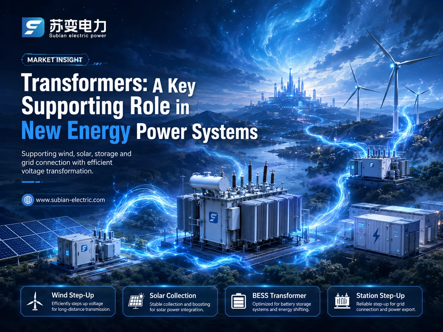
دور المحولات في أنظمة الطاقة الجديدة
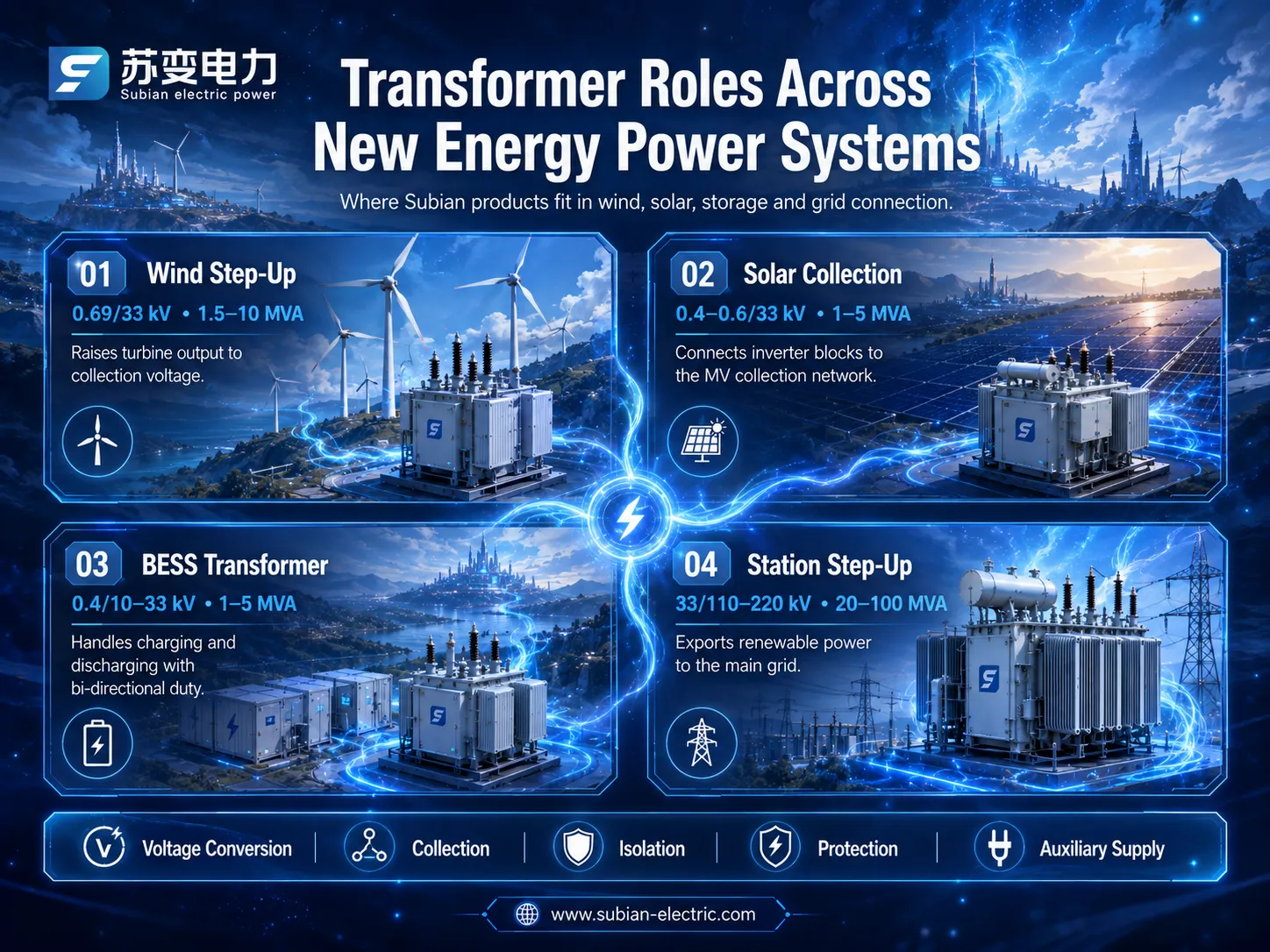
إن تشغيل أنظمة الطاقة الجديدة مشابه لتشغيل أنظمة الطاقة التقليدية، ولكن فقط على أساس مصادر الطقس الموزعة المعتمدة. تقليديًا، تؤدي المحولات خمس وظائف رئيسية:
محول رفع للمولد: ينقل الجهد المنخفض القادم من كل توربين أو سلسلة عاكس في نظام الجمع إلى جهد أعلى؛;
محول نظام الجمع: ينقل الطاقة من العديد من المولدات إلى المحطات؛;
محول رفع: يزيد من جهد الجمع لمزيد من النقل؛;
محول عزل: يقوم بفصل بين التوليد والشبكة؛;
محول إمداد مساعد: يوفر خدمات مساعدة لمحطة التحويل.
توبولوجيات النظام: الرياح، الشمس، التخزين، الهجين
يعتمد تكوين المحول على نوع المصدر وحجم المحطة:
| النظام | مراحل المحول النموذجية | أمثلة على التصنيف |
|---|---|---|
| الرياح البحرية (20–200 ميغاوات) | توربين 0.69/33 كيلو فولت → محطة 33/110–220 كيلو فولت | رفع 1.5–10 م.ف.أ؛ محطة 20–100 م.ف.أ |
| الرياح البحرية | رفع التوربين → محطة تحويل بحرية → محطة على اليابسة | رفع 5–15 م.ف.أ؛ محطة 100–400 م.ف.أ |
| الطاقة الشمسية المرفقية (10–200 ميغاوات) | عاكس 0.4–0.6/33 كيلو فولت → محطة 33/110–220 كيلو فولت | جمع 1–5 م.ف.أ؛ محطة 20–100 م.ف.أ |
| تخزين البطارية (10–100 ميغاوات) | PCS 0.4/10–33 كيلو فولت → محطة رفع | محول PCS 1–5 م.ف.أ |
| هجين (رياح + شمس + تخزين) | كل ما سبق في محطة تحويل واحدة | محولات محطات متعددة اللف |
كل مرحلة تضيف خسارة وتكلفة وأنماط فشل، ولهذا السبب يعمل مصممو الأنظمة بجد لتقليل عدد خطوات التحويل - لكن مستويات الجهد في أنظمة النقل الحديثة تجعل الخطوات لا مفر منها. المحولات هي ثمن نقل الطاقة المتجددة بكفاءة عبر المسافات.
واجب الطاقة الجديدة: المقارنة مع واجب الشبكة
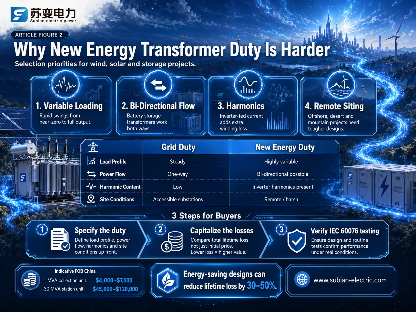
يجب أن تتعامل المحولات الجديدة للطاقة مع ظروف تشغيل غير شائعة لمحولات توزيع الشبكة:
أحمال متغيرة: إنتاج الطاقة من الرياح والشمس يتقلب من شبه صفر إلى كامل في بضع دقائق، مما يتسبب في تعرض لفات المحولات لتغيرات سريعة في درجة الحرارة وإجهاد العزل.
تدفق الطاقة في اتجاهين (طاقة البطارية): تحتاج محولات البطارية إلى نقل الطاقة في كلا الاتجاهين بنفس الأهمية، مما يعني إجهاد حراري متماثل لا يتم تصميم محول الشبكة أحادي الاتجاه له.
التوافقيات: تقوم العاكسات والمحولات بحقن تيارات ترددية تؤدي إلى خسائر إضافية في الطاقة في اللفات ويمكن أن تسبب رنينًا مع مقاومة المحول.
موقع بعيد: يتم وضع محولات توربينات الرياح على قمم الجبال أو في البحر في مياه مالحة، وظروف جوية قاسية، ومع مساحة محدودة للصيانة.
نتيجة لذلك هي تقليل القدرة، وتحسين التبريد، وتصميم اللفات للتعامل مع التوافقيات، واستخدام عزل قوي. قد لا يعمل المحول المصمم لمهام الشبكة المستقرة كما هو مذكور في ورقة المواصفات عند تركيبه في مشروع طاقة متجددة، وسيسخن ويفشل في وقت أقرب مما هو مخطط له.
| حالة التشغيل | واجب الشبكة النموذجي | واجب الطاقة الجديدة | استجابة التصميم |
|---|---|---|---|
| ملف الحمل | ثابت نسبي، قابل للتنبؤ | تقلبات سريعة من شبه صفر إلى كامل | تصنيف الحمل الدوري، هامش حراري |
| اتجاه تدفق الطاقة | اتجاه واحد (من الشبكة إلى الحمل) | ثنائي الاتجاه في محطات التخزين | تصميم لفات وتبريد متماثل |
| محتوى التوافقيات | منخفض، في الغالب 50/60 هرتز | توافُر توافُق العاكس | لفات مصنفة هارمونيك، هامش إضافي |
| الموقع | محطات فرعية مع وصول للخدمة | بعيد، في عرض البحر، هواء مالح، ظروف قصوى | حماية من التآكل، تصاميم محكمة |
الدرس العملي هو تحديد المواصفات وفقًا للواجب، وليس الجهد. يمكن أن يكون المحول الذي يناسب محطة توزيع بشكل مثالي هو الخيار الخاطئ بنفس التصنيف في محطة رياح أو طاقة شمسية.
أنواع المحولات وتكويناتها
العائلات الرئيسية للمحولات في أنظمة الطاقة الجديدة، مع التركيز على تصميمها:
| النوع | التصنيف النموذجي | التركيز على التصميم |
|---|---|---|
| رفع جهد التوربينات (WTS) | 5–15 م.ف.أ، 0.69/33 ك.ف | مدمجة، مقاومة للتآكل، تحمل اهتزازات عالية |
| محول العاكس الشمسي | 1–5 م.ف.أ، 0.4–0.6/33 ك.ف | لفات تتحمل الهارمونيك، فقدان حمل منخفض عند الدورات العالية |
| محول تخزين البطارية | 1–5 م.ف.أ، 0.4/10–33 ك.ف | قدرة تحميل ثنائية الاتجاه، هامش تحميل زائد عالي |
| محول محطة التجميع | 10–40 م.ف.أ، 33/110–220 ك.ف | محول تغيير موصل تحت الحمل، خسائر منخفضة، موثوقية عالية |
| محول مساعد | 50–500 ك.ف.أ، 33/0.4 ك.ف | أحمال بيت المحطة، مدمجة وموثوقة |
تظهر المحولات من النوع الجاف والمحولات المصبوبة بشكل متزايد في مرحلة العاكس وPCS للتثبيتات الداخلية أو الحاويات، حيث تفضل السلامة من الحرائق والوصول للصيانة العزل الصلب. تهيمن الوحدات المغمورة في السائل على مراحل الجمع والمحطة الخارجية.
كفاءة واعتبارات الخسارة
كفاءة محولات الطاقة الجديدة معقدة بطبيعتها. تشكل الخسائر الطاقة التي لا تستطيع المحطة بيعها، مما يقلل من دخلها. علاوة على ذلك، يعتمد مقدار الخسارة على التغيرات في الحمل. لمواجهة المشكلة، يجب اتباع مبدأين تصميميين:
خسارة عدم الحمل هي العامل الأكثر أهمية تحت الحمل المنخفض. عندما لا تنتج محطة الطاقة الشمسية أي مخرجات في الليل، فإن المحولات لا تزال تعمل، مما يؤدي إلى خسائر في القلب تصل إلى 8,760 ساعة في السنة؛;
خسارة الحمل هي العامل الثاني الذي يمكن أن يصبح أساسيًا عندما يكون الحمل مرتفعًا. حيث ترفع الهارمونيك خسارة الحمل بنسبة 5-20%، من الضروري أخذ هذا الجانب في الاعتبار عند وضع تصميم لفات المحول.
يمكن أن يوفر محول كفء للطاقة لمحطة الطاقة الشمسية من 30% إلى 50% من إجمالي خسائر المحول الذي له نفس القدرة. في المعادل النقدي، يمكن أن يكون ذلك مساوياً لـ $10,000 إلى $40,000 سنويًا مع الأخذ في الاعتبار تكلفة الطاقة $0,08 إلى $0,10 لكل كيلوواط ساعة.
| حجم المحطة | أسطول المحولات النموذجي | توفير الطاقة السنوي مقابل المواصفات العامة | القيمة السنوية عند $0.09/كيلوواط ساعة |
|---|---|---|---|
| 10 ميغاوات شمسية | 10 × 1 م.ف.أ وحدات جمع + وحدة محطة واحدة | 30,000–60,000 كيلوواط ساعة | $2,700–$5,400 |
| 50 ميغاوات شمسية | 25–30 وحدة جمع + محطة | 110,000–440,000 كيلوواط ساعة | $10,000–$40,000 |
| 30 ميغاوات رياح | 20 × 1.5 م.ف.أ وحدات توربينات + محطة | 90,000–250,000 كيلوواط ساعة | $8,100–$22,500 |
| 50 ميغاوات / 100 ميغاوات ساعة تخزين | 10–20 وحدات PCS + محطة | 70,000–200,000 كيلوواط ساعة | $6,300–$18,000 |
تتناسب التوفير مع حجم المحطة ويتفاقم عند استخدام المحولات العامة، وهذا هو السبب بالضبط في أن نموذج خسارة مستوى المحطة أصبح جزءًا من هندسة مشاريع الطاقة المتجددة.
الحماية، المراقبة، والموثوقية
تلعب المحولات دورًا مساعدًا إذا كانت تعمل. بسبب ذلك، تستخدم محطات الطاقة الجديدة عدة أدوات جنبًا إلى جنب مع المحولات مثل:
– المرحلات الواقية: محولات المحطة المزودة بكل من المرحلات التفاضلية ومرحلات التيار الزائد، وحماية الفيوزات وقواطع الدائرة على مستوى نظام التجميع.
– محلل الغاز المذاب: استخدام أخذ عينات الزيت وفقًا لـ IEC 60599 من أجل تحديد الأعطال المبكرة التي يمكن أن تكون حيوية في حالة كيفية تشغيل المعدات البعيدة.
– مراقبة درجة الحرارة والضغط: حساسات درجة حرارة الزيت العلوي والملفات.
– محولات التحويل تحت الحمل: كجزء من معدات محطة المحولات للمساعدة في الحفاظ على مستويات الجهد أثناء تشغيل محطة الطاقة.
– نظام المراقبة الذكية: الآن جانب معتاد يسمح بجمع البيانات المذكورة أعلاه وتحسين عملية الإرسال.
اقتصاديات الموثوقية واضحة: عندما تفشل مجموعات الطاقة بقدرة 30 MVA، يمكن أن يتأخر توليد 30-100 MW لأسابيع بتكلفة تصل إلى ملايين الدولارات. المحولات هي فقط تكلفة بسيطة مقارنة بالمخاطر المرتبطة بمثل هذه الإزعاجات التي تؤثر على جودة المعدات المستخدمة في المشاريع.
تحديد الحجم والاختيار لمشاريع الطاقة المتجددة
عند اختيار المحولات لنظام طاقة جديد، يجب اتباع الخطوات الموضحة أدناه.
تحديد ملف الحمل: يتضمن ذلك الحصول على الناتج الساعي من نموذج التوليد، ويشير إلى ملف الناتج المستمد من سلسلة سرعة الرياح أو الإشعاع الشمسي، وجدول الشحن/التفريغ.
تحديد حجم كل مرحلة من المحولات باستخدام طرق تخفيض القدرة: هنا يجب تطبيق تخفيض القدرة التوافقي، والذي يكون عادةً 5–10%، بالإضافة إلى طرق تخفيض القدرة لدرجة الحرارة المحيطة.
معرفة توازن الخسارة: تتكون هذه الخطوة من تشغيل رأس المال الخسارة عبر التعريفة والناتج.
تحديد أجهزة الحماية والمراقبة التي يجب تضمينها في الحل، مثل المرحلات وDGA.
تحديد المواصفات البيئية: يشمل ذلك لوائح الضوضاء، نوع الزيت وحماية التآكل.
اختبار الأجهزة وفقًا للمعايير.
الشركات المصنعة ونطاقات الأسعار
أسعار FOB الإرشادية لمحولات الطاقة الجديدة حسب العلامة التجارية والمرحلة:
| العلامة التجارية | الأصل | وحدة تجميع بقدرة 1 MVA | وحدة محطة بقدرة 30 MVA |
|---|---|---|---|
| هيتاشي للطاقة | اليابان/عالمي | $9,000–$14,000 | 95,000–160,000 |
| ABB | سويسرا/عالمي | $8,500–$13,500 | $90,000–$150,000 |
| سيمنز للطاقة | ألمانيا/عالمي | $8,000–$13,000 | 85,000–145,000 |
| شنايدر إلكتريك | فرنسا/عالمي | 7,500–12,500 | $80,000–$140,000 |
| توشيبا / هيونداي | اليابان/كوريا | $7,000–$11,500 | 75,000–130,000 |
| شركة جيانغسو سوبين للطاقة الكهربائية | الصين | $4,000–$7,500 | 45,000–120,000 |
تختلف الأسعار حسب التصنيف، نسبة الجهد، فئة الخسارة، محول التحويل، نوع الزيت، أسعار النحاس، وشروط التسليم؛ اعتبر هذه كمدى تخطيطي، وليس اقتباسات ثابتة.
يرسخ المستوى المتميز السوق من خلال برامج اختبار النوع العالمية وسجلات الأداء في البحر. يقدم المستوى الصيني نفس أدلة IEC 60076 وتصاميم محددة للطاقة الجديدة بتكلفة أقل تتراوح بين 40–50%، مما جعله مصدرًا رائدًا لمشاريع الرياح البرية والطاقة الشمسية والتخزين عبر آسيا وأفريقيا والشرق الأوسط وأمريكا الجنوبية. شركة جيانغسو سوبين للطاقة الكهربائية هي شركة صينية مصنع المحولات القادر و محول موفر للطاقة منتج يزود المحولات من نوع رفع التوربينات، وجمع الطاقة الشمسية، والتخزين، ومحطات الطاقة من 10 kVA إلى 63 MVA، مع لفات تتحمل التوافقيات، ومغيرات التحميل، وخيارات النواة غير المتبلورة وزيت الإستر الطبيعي، جميعها مختبرة وفقًا لمعيار IEC 60076 ومزودة بتقارير اختبار روتينية. قامت Subian بتزويد مشاريع الطاقة المتجددة والتخزين دوليًا؛ النطاق موثق في subian-electric.com.
التوقعات: المحولات في أنظمة الطاقة المستقبلية
ستحدد وظائف المحولات من خلال ثلاثة اتجاهات في نظام الطاقة المتجددة المحلي خلال السنوات العشر القادمة. أولاً، سيكون هناك توسع سريع في تركيب محولات الطاقة المتجددة، وهو أمر ضروري نظرًا لأن التقديرات العالمية تتوقع زيادة حصة الطاقة المتجددة في إنتاج الكهرباء في الأسواق الرئيسية من 30% إلى ما يصل إلى 50-70%، مما يعني بدوره أن كل جيجاوات مثبتة من القدرة ستتطلب العشرات من المحولات. ثانيًا، ستصبح الكفاءة أكثر تشددًا مع استمرار تصنيفات الكفاءة والمشتريات الخضراء في الزيادة، مما يجعل المحول الأخضر التصاميم هي الافتراضية. ثالثًا، ستصبح المراقبة الذكية معيارًا، لأنه في نظام حيث يكون الناتج متغيرًا وبعيدًا، فإن البيانات التي تحافظ على صحة المحولات هي البيانات التي تحافظ على تدفق الطاقة المتجددة.
ستظل المحولات في خلفية انتقال الطاقة — لكن الانتقال ببساطة لا يحدث بدونها.
الأسئلة المتكررة
ما هي المحولات المستخدمة في محطات الرياح والطاقة الشمسية؟
عادةً ما تكون هناك ثلاث مراحل: محولات رفع التوربينات/العواكس (0.69/33 kV أو 0.4–0.6/33 kV، 1–15 MVA)، وحدات شبكة الجمع، ومحولات رفع المحطة (33/110–220 kV، 20–400 MVA). تضيف محطات تخزين البطاريات محولات PCS ثنائية الاتجاه عند 0.4/10–33 kV.
كم تكلف المحولات لمحطات الطاقة المتجددة؟
تعمل محولات الجمع بقدرة 1 MVA بحوالي $4,000–$7,500 FOB من الشركات المصنعة الصينية؛ تعمل محولات المحطة بقدرة 30 MVA بسعر $45,000–$120,000. تسعّر العلامات التجارية الدولية المتميزة بزيادة تتراوح بين 50–80%. تختلف الأسعار حسب التصنيف، وفئة الفقد، ومغير التحميل، وأسعار النحاس.
لماذا تعتبر خسائر المحولات مهمة في أنظمة الطاقة الجديدة؟
لأن كل كيلووات مفقود هو ناتج متجدد لا يمكن بيعه أبدًا. تبقى محولات محطة الطاقة الشمسية نشطة في الليل عندما يكون الناتج صفرًا، لذا فإن خسائر عدم التحميل تهم أكثر مما يوحي حجمهما الصغير. في محطة بقدرة 50 MW، يمكن أن توفر المواصفات الصحيحة $10,000–$40,000 سنويًا في طاقة الفقد.
هل تختلف المحولات المتجددة عن المحولات العادية للشبكة؟
نعم، في الخدمة. إنهم يرون تحميلًا متغيرًا وثنائي الاتجاه، وتوافقيات من العاكسات، ومواقع بعيدة أو قاسية. يتطلب ذلك لفات مصنفة للتوافقيات، وتقليل التصنيف، وتبريدًا أفضل، وحماية من التآكل. استخدام محول شبكة قياسي دون تقليل التصنيف يقصر من عمره.
ما هي مدة حياة المحول في محطة الطاقة المتجددة؟
20-35 سنة، اعتمادًا على شدة التحميل، وظروف البيئة، والصيانة. يقلل التحميل المتغير والتوافقيات من العمر الافتراضي ما لم يتم تقليل تصنيف الوحدة ومراقبتها. تعتبر قياسات DGA السنوية وفقًا لـ IEC 60599، ومراقبة درجة الحرارة، والحفاظ على درجة حرارة النقاط الساخنة ضمن حدود IEC 60076-7 من أقوى العوامل المؤثرة على العمر الافتراضي.
المراجع
- IEC 60076-1: محولات الطاقة - عام — معيار دولي ومرجع للاختبار لجميع محولات أنظمة الطاقة المتجددة.
- IEC 60076-5: القدرة على تحمل الدائرة القصيرة — التحقق من تصميم الدائرة القصيرة لمحولات المحطة.
- IEC 61936-1: التركيبات الكهربائية التي تتجاوز 1 كيلو فولت تيار متردد. — متطلبات التركيب لمحطات الطاقة المتجددة ذات الجهد المتوسط والعالي.
- IEA الطاقة المتجددة 2023 — بيانات نمو الطاقة المتجددة العالمية التي تدعم الطلب على المحولات.
- تكنولوجيا الطاقة المتجددة IRENA — نظرة مستقبلية للتكنولوجيا في تكامل الرياح والطاقة الشمسية والتخزين.
- GB 20052: درجات كفاءة الطاقة للمحولات الكهربائية — درجات الكفاءة المتعلقة بمواصفات المحولات المتجددة.
- الموقع الرسمي لشركة جيانغسو سوبين للطاقة الكهربائية — مجموعة المحولات المتجددة والتخزين مع تقارير الاختبار.
الخاتمة
تعتبر المحولات عناصر مهمة في أنظمة الطاقة الحديثة — بمعنى هيكلي بدلاً من اختياري. كل توربين رياح، حقل شمسي، ومنشأة بطارية تعتمد على المحولات لرفع الجهد، وجمع الطاقة والاتصال بالشبكة، وبالتالي يجب تصميم كل محول لتحمل التحديات التي تفرضها هذه الأنظمة: الأحمال المتغيرة، التشويه، الحركة ثنائية الاتجاه، والمواقع النائية.
النقاط الرئيسية:
- تحتاج الأنظمة المتجددة إلى ثلاث مراحل تحويل: رفع الجهد أثناء التوليد، الجمع، ورفع الجهد في المحطة.
- واجب الطاقة الجديدة أصعب من واجب الشبكة — تقليل التصنيف، تحمل التوافقيات، والمراقبة أمور غير قابلة للتفاوض.
- يوفر تحديد الكفاءة 30–50% من الطاقة المفقودة سنويًا مقارنةً بوحدة عامة؛ تعادل $10,000–$40,000 سنويًا في محطة بقدرة 50 ميغاوات.
- ميزانية $4,000–$7,500 لوحدات الجمع بقدرة 1 MVA و$45,000–$120,000 لوحدات المحطة بقدرة 30 MVA من الشركات المصنعة الصينية.
إذا كنت تبني أو توسع مشروعًا للرياح أو الطاقة الشمسية أو التخزين أو الهجين،, شركة جيانغسو سوبين للطاقة الكهربائية توفر محولات بدرجة متجددة من 10 kVA إلى 63 MVA — تتحمل التوافقيات، تم اختبارها وفقًا لمعيار IEC 60076، مع خيارات نواة غير متبلورة وزيت استر — بأسعار تنافسية للتصدير. راجع المجموعة في subian-electric.com.