


المحولات الرافعة والمحولات الخافضة تستخدم نفس المبادئ الفيزيائية عبر الحث الكهرومغناطيسي لتغيير جهد التيار المتردد عندها ولكنها تقع على جانبي الشبكة الكهربائية وتكون متعاكسة من حيث الوظائف التي تؤديها من حيث الجهد والتيار. على الرغم من أنها تعمل بنفس الآلية، إلا أن ذلك لا يعني أنها تختلف من حيث جودة البناء. بل، يكمن الاختلاف الكامل بينهما في حقيقة أن أحد المحولات لديه ملف مع لفات أكثر من الآخر وهذا سيحدد كيف سيؤثر المحول على الجهد والتيار اعتمادًا على مكان التركيب وسيكون له أيضًا تأثير كبير على سعر الآلة. تشرح هذه المقالة جميع ميزات أنواع المحولات وتقدم نصائح عملية لمشتريها.
الجواب هو كما يلي: تم تصميم المحول الرافعة مع لفات أكثر على ثانويته مقارنةً بأساسيته، مما يؤدي إلى جهد أعلى عند المخرج مقارنةً بالدخل. يتم تطبيق نفس المبدأ لتقليل الخسائر المقاومة من خلال نقل الطاقة عند جهد أعلى باستخدام هذه الطريقة. يحتوي المحول الخافض على عدد أقل من اللفات في الثانوي مقارنةً بالأساسي؛ لذلك، فإنه ينتج جهدًا أقل مع زيادة متناسبة في تيار الخرج. كلا النوعين من المحولات يعتمد على نفس المعادلة Vs/Vp = Ns/Np؛ ومع ذلك، مع كون التيار متناسبًا عكسيًا. سيعمل المحول كأحد النوعين، إذا تم تركيبه بالعكس، ولكن قد لا تنتج المحولات الخافضة دائمًا خرجها المقدر عند تحويلها إلى رافعة بسبب بناء اللفات، والعزل، ونظام التبريد المتعلق بوضع معين لتدفق الطاقة.
ما هما النوعان
كلا الجهازين هما نوعان من الآلات الثابتة. يحتوي كل منهما على لفات اثنتين أو أكثر على نواة مغناطيسية. تحمل اللفة الأساسية تيارًا مترددًا وتنتج تدفقًا متغيرًا داخل النواة المغناطيسية. ينتج التدفق جهدًا محثوثًا في الأخرى، والتي تُسمى اللفة الثانوية. اللفتان غير متصلتين كهربائيًا ببعضهما البعض في محول ذو لفّتين. في كلا الجهازين، لا توجد أجزاء متحركة.
السمة التصميمية الوحيدة التي تفصل بين المحول الرافعة والمحول الخافض هي نسبة اللفات. في حالة وجود عدد أكبر من اللفات في اللفة الثانوية مقارنةً باللفة الأساسية، يصبح الجهد المحثوث في اللفة الثانوية أعلى، ويكون المحول محولًا رافعًا. إذا كانت اللفات في اللفة الثانوية أقل من تلك في اللفة الأساسية، فهذا يعني أن جهدها أقل ويكون المحول محولًا خافضًا. تشير جميع الميزات الأخرى للمحول إلى الطريقة التي يتم بها تحقيق نسبة اللفات المذكورة.
من المهم أن نقول إن هذه هي النقطة الدقيقة لفهم خاطئ شائع إلى حد ما. النقطة هي أن المحول الرافعة ليس أكثر قوة من المحول الخافض. حقيقة أن المحول الرافعة لديه تصنيف طاقة يبلغ 500 kVA لا تعني أنه سيكون آلة أكثر قوة من المحول الخافض بنفس الطاقة.
كيف يعمل محول الرفع
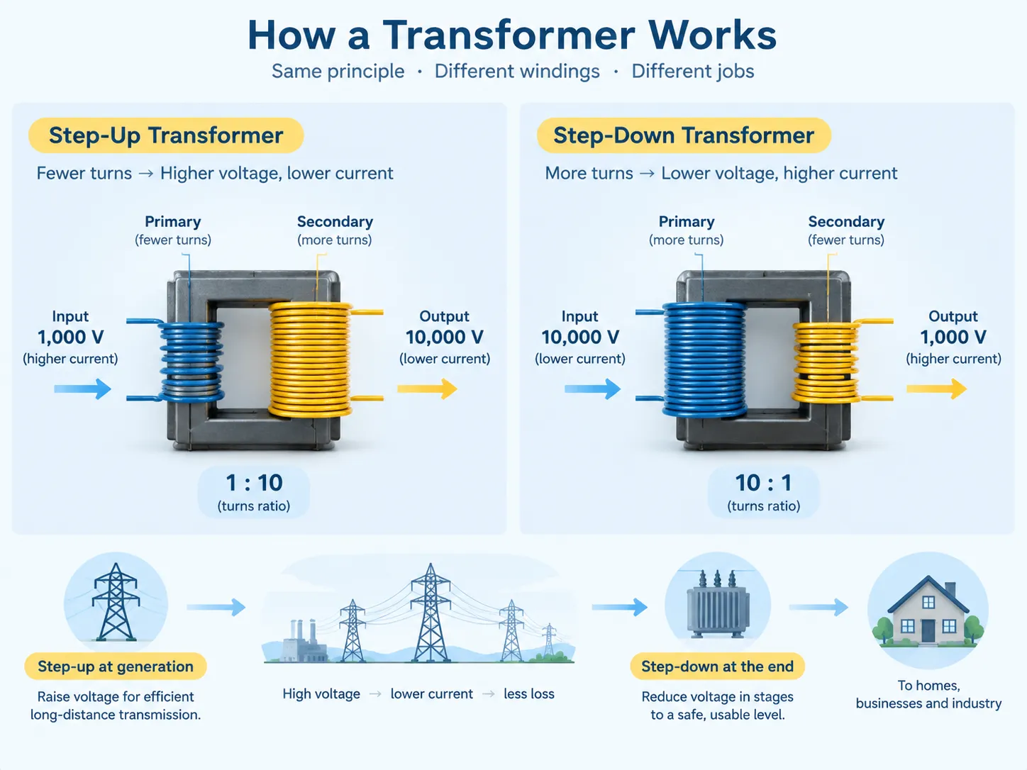
استخدام المحول الرافعة يعني أن إمداد الكهرباء يتم تغذيته إلى الملف الذي يحتوي على عدد أقل من اللفات ويتم أخذ الاستخدام من الملف الذي يحتوي على عدد أكبر. إذا كان عدد لفات الملف الأول 100 وعدد لفات الملف الثاني 1,000، فإن نسبة اللفات تعطي 1:10 ويجب أن تكون الجهد عند النقطة الثانوية من المحول أعلى بعشر مرات من تلك عند النقطة الأولية، مع بعض الاستثناءات المتعلقة بالخسائر والتنظيم.
النقطة الرئيسية هي التأثير على التيار. نظرًا لأن المحول لا ينشئ الطاقة بل ينقلها فقط، إذا زاد الجهد، ينخفض التيار. على سبيل المثال، إذا مر المحول الرافعة بجهد 10,000 فولت من إمداد 1,000 فولت، سينخفض التيار إلى عُشر التيار الأولي في الملف الأول. هذه العلاقة ليست عيبًا في المحول، بل هي هدفه الرئيسي طالما أنه من الواضح أن الجهد الأعلى يعني تيارًا أقل وفقًا للقانون الفيزيائي العام.
لذلك، يمكن للمرء أن يجد جزءًا من المحول الرافعة في جميع أنظمة الطاقة من جانب توليد الطاقة. يقوم المولد بإنشاء الكهرباء عند جهد مقيد بالعزل أو بشكل أكثر دقة من 11 kV إلى 25 kV في المولدات الكبيرة. بعد ذلك، يقوم المحول الرافعة بزيادة هذا الجهد إلى القيمة المطلوبة للنقل، والتي قد تتراوح من 275 kV إلى 400 kV وأكثر. الأسس التي يتم بناء هذه الآلات عليها وأين تقع في الشبكة موضحة في البناء الأساسي ودور محولات التوزيع, ، التي تشترك في نفس المبادئ على نطاق أصغر.
كيف يعمل المحول الخافض
في المحول الخافض، يتم عكس ترتيب اللفات، حيث يتم تطبيق الإمداد على الملف الذي يحتوي على عدد أكبر من اللفات ويتم أخذ الحمل من الملف الذي يحتوي على عدد أقل من اللفات. في مثال المحول الخافض مع نسبة 10:1، عند تغذيته بـ 10,000 فولت، سيزود 1,000 فولت، بينما يزيد التيار الناتج أيضًا بنفس عامل 10.
واحدة من الأسباب لوجود المحولات المخفضة هي أن هناك فرق كبير بين الجهد الذي يكون فعالًا للنقل من نقطة التوليد إلى نقطة الاستخدام. بينما يمكن استخدام جهد النقل 275 كيلوفولت للنقل لمسافات طويلة، لا يمكن توصيل أي مباني أو معدات أو أجهزة بهذا الجهد العالي. يجب تقليل الجهد تدريجياً إلى المستوى المناسب للاستخدام العملي. لهذا الغرض، يمكن تقليله على مراحل عديدة من النقل إلى النقل الفرعي، ثم التوزيع الأولي وأخيراً إلى المستوى المقبول للتثبيتات. قد يتعين إجراء عدة تحويلات مخفضة قبل أن يتم تأسيس الإمداد.
يجب ذكر بعض الميزات المتعلقة بعمل المحول المخفض. أولاً وقبل كل شيء، إذا انخفض الجهد، فإن التيار يحمل قيمة أعلى بكثير عند لف الجهد المنخفض مقارنةً بلف الجهد العالي، ولهذا السبب يجب أن يكون لف الجهد المنخفض أثقل من نظيره الجهد العالي - وهذا هو السبب في أنه من السهل التعرف على لف الجهد المنخفض للمحول. ثانياً، يُعتبر استقرار الجهد أكثر أهمية عند المخرج حيث أن التثبيت يتحمل فقط نطاقًا معينًا من الجهد. يتم شرح مجموعة كاملة من معلمات لوحة الاسم والمواصفات، وكيف يؤثر كل منها على السلوك في الخدمة في تفسير مواصفات المحولات.
مقارنة جنبًا إلى جنب
| المعامل | محول رفع الجهد | محول خفض الجهد |
|---|---|---|
| نسبة اللفات | لفات ثانوية > لفات أولية | لفات ثانوية < لفات أولية |
| الجهد | الناتج أعلى من المدخل | الناتج أقل من المدخل |
| التيار | الناتج أقل من المدخل، بنسب عكسية | الناتج أعلى من المدخل، بنسب عكسية |
| الطاقة | غير متغير باستثناء الفقد | غير متغير باستثناء الفقد |
| الوظيفة الأساسية | رفع الجهد لتقليل خسائر النقل | تقليل الجهد إلى مستوى قابل للاستخدام |
| الموقع النموذجي | عند التوليد، وعند النقاط التي يجب فيها رفع الجهد للتوزيع | عند المحطات الفرعية، عند نقاط إمداد المباني، وعند كل نقطة استخدام |
| أزواج الجهد النموذجية | 11-25 كيلوفولت إلى 132-400 كيلوفولت | 132-400 كيلوفولت إلى 11-33 كيلوفولت، ثم إلى 400 فولت أو 230 فولت |
| لف أثقل | ثانوي (جهد عالي)، على الرغم من أن العزل يهيمن | ثانوي (جهد منخفض)، لأن التيار أعلى |
| التركيز على العزل | ثقيل - لف الجهد العالي يدفع التصميم والمسافات الفاصلة | معتدل من الجانب العالي، الحد الأدنى من الجانب المنخفض |
| التكلفة النسبية النموذجية عند نفس MVA | أعلى، بسبب متطلبات العزل والمسافات الفاصلة | أقل لنفس تصنيف القدرة الظاهرة |
| الكفاءة | مرتفع جدًا، عادةً 98-99% عند التصنيفات الكبيرة | مرتفع جدًا، عادةً 97-99% حسب الحجم |
| قابل للعكس من حيث المبدأ | نعم، إذا تم تغذيته من الخلف ضمن حدود التصميم | نعم، إذا تم تغذيته من الخلف ضمن حدود التصميم |
تتطلب صف واحد بعض التوضيح لأنه يفاجئ العملاء. إذا كانت كلا النوعين من المحولات تتعامل مع نفس الطاقة، لماذا يكون المحول الرافعة أكثر تكلفة من نظيره؟ الجواب في نظام العزل. يجب أن يتعامل المحول المصمم مع جهد ثانوي عالي مع الجهد في عزل اللف، والمسامير، والمسافات إلى الأرض، ومقاومة الصدمات. تعتمد هذه المتطلبات على الجهد بدلاً من الطاقة. وبالتالي، فإن محول رافع بقدرة 50 MVA بجهد 11 kV/132 kV سيكون عادةً كبيرًا ومع عزل أفضل وأكثر تكلفة من محول خافض بقدرة 50 MVA بجهد 132 kV/11 kV على الرغم من أن كلا الوحدتين قد تبدوان متشابهتين في المواصفات.
How They Differ Physically
The external appearance of a step-up and a step-down transformer with the same specifications can be confusing due to the similar construction. And yet, there are certain features the transformer has that help determine its type.
- Bushing height and size. Thanks to the high-voltage winding, the bushing design is different. With that in mind, it is easy to tell which side is used for high-voltage transmission. In a step-up transformer that would be the secondary winding, while in a step-down transformer, it would be the primary one.
- Winding conductor cross-section. If there is an opportunity to make a visual check, it is possible to say whether the winding belongs to a step-up transformer or a step-down transformer by the thickness of the conductors.
- Cooling arrangement. In case of the larger units of both speculations, there are radiators, fans or pumps to provide oil for cooling, but it is not a distinguishing feature for both types, as the cooling class is given in the rating plate.
- Taps used in the winding. The tap changer is usually installed on the high-voltage winding, as this construction allows fine tuning of the transformer for the same number of turns in the winding.
In all cases, the nameplate proves to be of great help in deciding which type of the transformer is available.
Where Each Is Used
The two types occupy opposite ends of a chain that every unit of electricity passes through.
| المرحلة | دور المحول | التصنيف النموذجي |
|---|---|---|
| التوليد | Generator step-up transformer raises machine voltage to transmission level | 50-1,000 MVA |
| النقل | Step-up and step-down at interconnection points between voltage levels | 100-1,000 MVA |
| النقل الفرعي | Step-down from transmission to sub-transmission voltage | 20-200 MVA |
| التوزيع الأساسي | Step-down from sub-transmission to distribution voltage | 5-50 ميغا فولت أمبير |
| محطة توزيع | Step-down to utilisation voltage for an area or a large site | 0.5-5 MVA |
| Point of use | Step-down to the installation’s operating voltage, or local step-up for a specific machine | 0.025-2.5 MVA |
| Specialist local use | Step-up for a specific process or test requirement, such as electrostatic precipitators or test benches | Varies widely |
It can be inferred from the last two rows that both forms of transformations can occur in the same factory facility. A factory can receive electricity by the step-down transformer and then it may have a small step-up transformer to use it for a specific process such as electrostatic precipitators or dielectric test sets, or special equipment which requires higher voltage than what is supplied through the distribution. The direction of the transformation depends on the needs and not on the place where it is located; thus, the sizing problem has to be solved based on the requirements in terms of voltage and power.Getting that arithmetic right is a prerequisite for specifying anything correctly, and the method is set out in the approach to transformer sizing and load calculation.
الأنواع والتكوينات
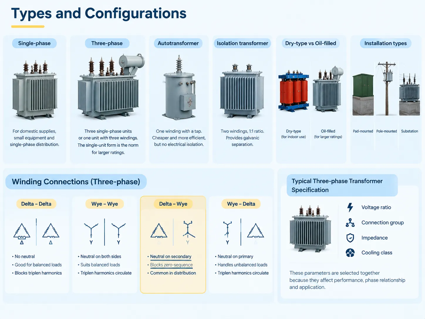
The construction family of the transformers does not tally with the direction of transformation, since both step-up and step-down transformers belong to the same family of construction.
- Single-phase. Made up of two windings on one core, widely used for home and small equipment supply and distribution, commonly used for smaller capacities.
- Three-phase. Consisting of either three single-phase transformers, or one three-phase transformer which has three windings on the same core. The second design favours the majority of transformer constructions due to its inherent capacity for powering transformers of very large rating and in providing installation with other parameters related to transformer operation.
- Autotransformer. A transformer with a single winding on tap that has electromagnetic coupling of circuits. It is the most cost-effective solution when compared to a two-winding transformer for similar purpose.
- Isolation transformer. A transformer with two windings and 1:1 turns ratio designed for specific needs of galvanic isolation.
- Dry and oil-filled types. Their distinction lies in the location where they are used: the dry type can work in closed spaces and the oil-filled ones are mostly employed for transformers that are big enough and have higher capacities, since oil cooling is more effective than air one.
- Pad-mounted and pole-mounted transformers, or transformers in substations. They are rather concerned with the installation methods than with the principle of transformers’ work.
For work done over three phases, the way the windings are connected — whether through delta or wye — significantly affects how phases of primary and secondary work together, along with whether a neutral is there and how unbalanced loads and triplen harmonics are handled by the transformer. An example would be a delta-wye connection that offers a neutral at the secondary and blocks the zero-sequence current from passing through it.The practical implications of each combination are significant enough to drive the specification, and a representative example of how a three-phase unit is presented for procurement is the نطاق المحولات الثلاثية الطور لدينا, where voltage ratio, connection group, impedance and cooling class appear together because they must be selected together.
Prices and Cost Drivers
Transformer pricing is conditioned by similar factors in the opposite direction, where direction of the installed unit does not matter as much as voltage class or voltage rating.
| Cost driver | Effect on price | لماذا |
|---|---|---|
| Power rating (kVA or MVA) | Dominant driver; price rises faster than rating | More core steel, more copper, more oil, larger tank |
| فئة الجهد | Major driver, especially on the high-voltage side | Insulation, clearances and bushing costs scale steeply with voltage |
| Cooling class (ONAN, ONAF, OFAF) | معتدل | Radiators, fans and pumps add cost but raise usable rating |
| Impedance specification | معتدل | Low impedance costs more in material; affects fault level and regulation |
| Tap changer (off-circuit or on-load) | Significant for on-load | On-load tap changers are complex mechanisms with their own controls |
| مواصفات الفقد | Significant | Low-loss designs use more active material to reduce operating cost |
| Connection group and neutral arrangement | Minor to moderate | Affects winding configuration and any neutral bushing |
For the buyer, the key factors are that when comparing price offers from multiple suppliers, a product specification should be taken into account, since, after all, cheap price often translates into cheaper voltage class, small cooling margin or higher losses than in a good deal; and that the price of the product is only one part of the total cost, since losses are paid throughout the entire service life of the product. Reconciling capital cost against lifetime energy cost is the central exercise in transformer procurement, and the realistic price bands for each rating and class are set out in the cost structure for electrical transformers.
Can a Step-Down Be Used as a Step-Up?
In theory, it is possible. A transformer is a reversible device and turning the supply towards what is being called its secondary will mean that the voltage on what is being called primary will be higher than expected. On some occasions, this is done on purpose in case of emergency.
However, in reality the following four points define the reason why this is a bad idea unless made as part of a rational engineering choice. They are usually installed on the high-voltage winding which implies that reverse feeding of the transformer will situate them in unsuitable places for voltage adjustment. The insulation and distances were made with the assumption that the high voltage will appear on a certain winding, but back-feeding can expose this voltage to a wiring arrangement not convenient for it. The parameters for cooling and current ratings were set with a certain current distribution through the windings assumed, which will now turn when the power flow gets reversed. The protection and earthing system that would normally be designed for a particular direction of power flow will not be suitable for reversed flow either.
To summarize, reversal is theoretically possible to do, may be appropriate in certain situations, but is better clarified with the manufacturer rather than assumed. If one does require both directions at site, using a transformer properly selected for the job would be a much smarter approach than compromising by using whatever transformer one happens to have.
How to Tell Which You Have
Four tests in an order of reliability.
- Check the rating plate. It states the rated voltage of each winding as identified by terminal markings as well as the rated power, type of connection group, impedance, and the class of cooling. This is the most accurate test and can be carried out within seconds. If it is not possible to identify rating plate because of its illegibility or absence then other tests will become just approximations.
- The next test is to make a comparison of bushings and the clearance. The high-voltage side is identified by the side where bushings are larger and spacing and clearance to the earth are wider.
- Make a check of the size of the conductors whenever it is possible to see it. The heavier conductor belongs to the winding with the higher current and lower voltage.
- Trace the connection. Follow the supply line to find out which winding is the primary one and compare it with the rated voltage of the winding being investigated.
There are two remarks about field identification. If a transformer has a ratio of 1:1, for example, that is the isolation transformer, it does not step-up or step-down voltage and an attempt to identify the transformer by the direction will yield only a wrong result. Moreover, a transformer having many taps can be connected in such a way as to change its nominal ratio. Thus what is shown on the plate may not reflect the actual situation.
الأسئلة الشائعة
What is the difference between step-up transformers and step-down transformers?
The differentiation resides in the number of coils in winding. A step-up transformer has a greater number of coils in the secondary coil because of which the voltage of the output is greater than that of the input as well as the current is less proportionately. The purpose of the step-up transformer is to boost the voltage level to ensure the efficiency of power transmission. Meanwhile, a step-down transformer decreases the number of coils in its secondary coil leading to the decrease of voltage and increase of current in the proportion. The step-down transformer is used to lower the voltage to an appropriate level. Though both transformers operate at the same efficiency level, the following equation is true for both types of transformers Vs/Vp = Ns/Np.
What is the disadvantage of a step-up transformer?
There are three drawbacks that should be taken into account. To begin with, with the same power rating, costs tend to be higher than for step-down transformers as the high-voltage winding uses insulated parts and clearance materials that are connected with voltage parameters rather than power output. Next comes the risk that is connected with the potential failure of insulation systems due to the greater power of possible failures in the case of using high voltage equipment. Thirdly, when one uses a step-up transformer supplying a long cable, it is necessary to address voltage rise at the cable ends due to low voltage load conditions. Despite the fact that step-up transformers are quite reliable under normal conditions, all of the indicated factors affect the process of their specification and protection.
Can a step-down transformer be used as a step-up transformer?
In terms of functionality, the transformer can certainly operate in a reverse mode as there are situations where this is done in emergency situations. However, a device that has been intentionally built for use as a step-down transformer will usually not be able to achieve its full capacity when connected to the line in reverse mode because of numerous factors including but not limited to the design of the transformer in terms of winding construction, number of taps in use, and cooling arrangements. In reverse operation, the taps will usually remain on the primary (high voltage) side which may be regarded as inappropriate for operation. It is always advisable to check the reversibility option with the manufacturer and the devices that are made specifically for this purpose should be installed rather than recompleting the one that was not made for reverse operation.
How to tell if it’s a step-up or step-down transformer?
Examine the rating plate, which provides the rated voltage for each winding and is conclusive. In the absence of the rating plate, compare the bushings; the side with the bigger bushings, greater spacing and larger clearance from earth is said to be the high-voltage side, meaning that it is the side to which the transformer steps up and down from. In instances where the conductors are visible, noting the sizes of the conductors is the second clue; since the larger conductor is used for the winding with the higher voltage and lower current. Then follow the supply line to find out which of the windings is in fact the primary, as transformers with various taps may not always be installed in the configurations that results in the effective ratio being same as in the nameplate specifications.
Which transformer is used in a substation?
In both cases, the substation serves the reciprocal function. In the primary substation, transmission voltage is lowered to the level of distribution voltage. Therefore, all transformers in this type of substation are called step-down transformers. In a generation facility, the substation serves a different purpose since it is raising the voltage produced by the generator to the level of voltage transmission by using a step-up transformer. When it comes to interconnection substations, they might work in both modes, as they may contain both step-up and step-down units depending on the direction in which electricity flows most frequently and switching the flow if the flow does not change at the generation and demand points.
المراجع
- International Electrotechnical Commission — IEC 60076 Power Transformers
- IEEE — Transformer Connections, Voltage Regulation and Loading Guides
- ANSI — ANSI C57 Series Power Transformers, Regulators and Reactors
- NFPA — National Electrical Code, Article 450 Transformers and Transformer Vaults
- U.S. Department of Energy — Transformer Efficiency and Distribution System Losses
الخاتمة
Step-up and step-down transformers are different sides of the same coin. The only difference is the number of turns in each transformer. In step-up transformers the secondary winding has more turns than the primary winding; thus, the transformer raises voltage and lowers current. Electricity transmission at high voltage is far more effective than doing so at low voltage — which is why the step-up transformer was invented in the first place. The step-down transformer on the other hand has fewer turns on the secondary winding and lowers voltage while raising current. Basically, there is no such thing as a transformer that could be connected to the transmission line. Both transformers transfer the same amount of power except for losses involved, and they obey the same formula Vs/Vp=Np/Ns. They are built in the same manner — the only thing that differentiates them is their position in the electric power transmission system and that makes step-up and step-down units price different. The step-down unit can be used as a step-up transformer but its efficiency will be the lowest because it is designed to work only in one way.