


A hospital experiences a power cut due to a storm. In no time, its batteries and generators will begin feeding the operating rooms, data room, and chillers while the main supply is disconnected so that power does not come back to the damaged line. The moment the utility returns, the facility must reconnect to the grid without setbacks; but this does not happen because battery or generators act alone. It is made possible with the help of switchgear equipment in conjunction with control systems which are responsible for the devices.
It might seem that microgrid switchgear implies special type of cabinets. In fact, microgrid switchgear stands for arrangement, rating and regulation of standard electrical protection apparatus at multi-source facility in a way that enables seamless operation in grid-connected and island mode.
In this guide, microgrid switchgear will be explained in details including the electrical architecture, sequence of islanding and connection, reasons why traditional protection settings fail in the case of working with inverters, and requirements for EPC constructors.
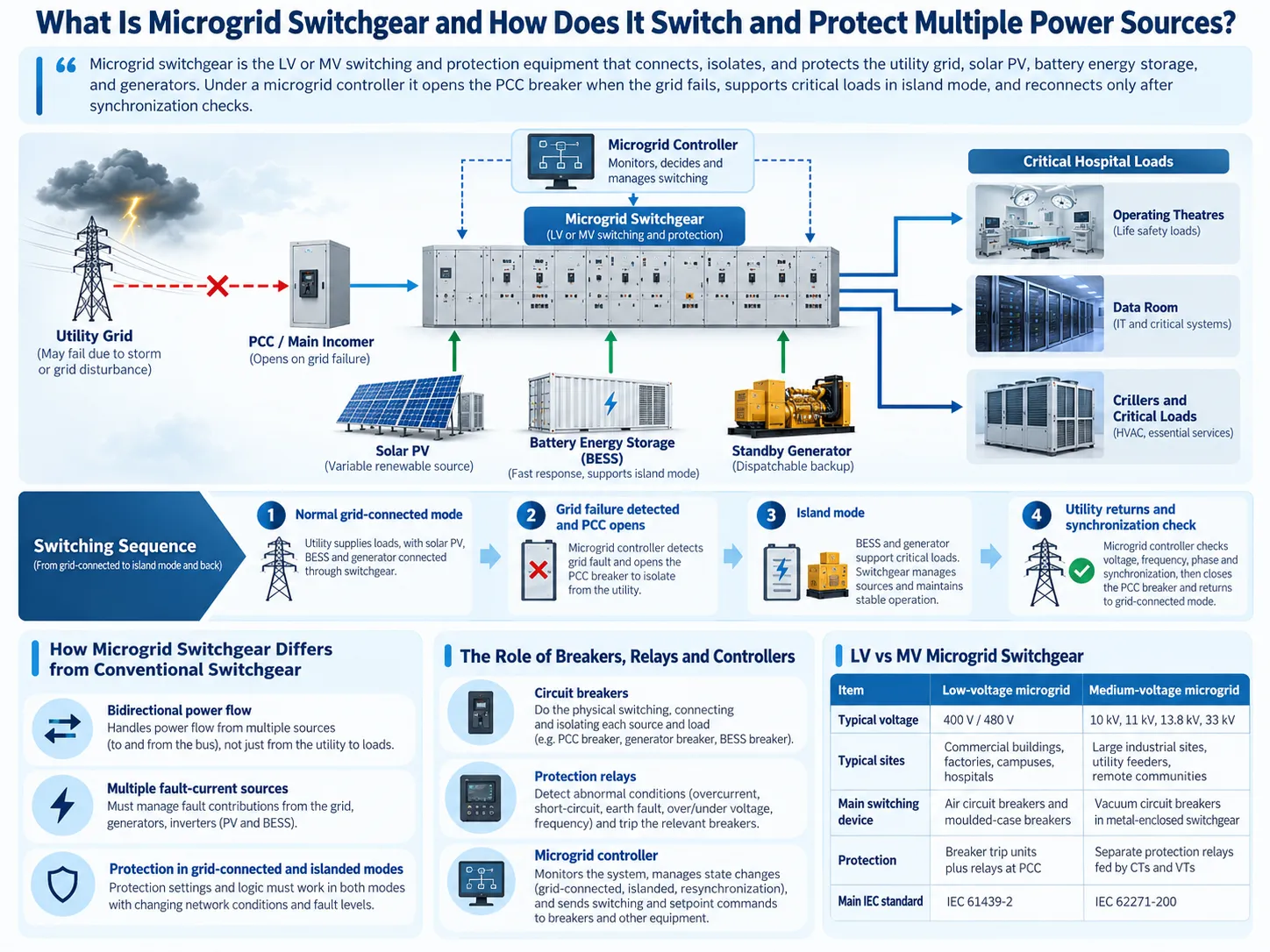
So what is microgrid switchgear? It is low or medium voltage switchgear that connects the microgrid sources and loads. Connected to microgrid controller, the switchgear opens the circuit in case of grid failure and allows local energy sources to power the facility in standalone mode; only after synchronization operations, when everything is ready for reconnection, the switchgear allows it to connect to the grid. The difference with conventional switchgear lies not in the design but in the coordination of protection and switching apparatus at multi-source facility.
What Is Microgrid Switchgear?
According to the U.S. Department of Energy, a microgrid is made up of interconnected loads and distributed energy resources contained in specific electrical boundaries and is capable of operating independently or alongside the grid as one functional system capable of connecting and disconnecting from the grid (Ton and Smith, The U.S. Department of Energy’s Microgrid Initiative). The switchgear is what establishes the respective physical limits of the microgrid.
How Microgrid Switchgear Differs from Conventional Switchgear
In the case of the conventional kind of distribution switchgear it is assumed that there exists only one principal source. The utility supplies power to loads and the fault current is also supplied by the utility with the help of protection set on that premise. The concept of microgrid breaks all three aforementioned assumptions. Thus, power can flow through the feeder in either direction, fault currents can originate from different sources simultaneously, and its value changes when the site is disconnected from the grid.
The equipment itself may look similar as it still comprises incomers, bus sections, feeder breakers and relays, but the performance specifications are different. Each source must have its own breaker and metering, the busbar layout design must allow adding or eliminating sources, and the protection system must be able to work in both operation modes.
The Role of Circuit Breakers, Relays and Microgrid Controllers
The three layers function together to produce a desired action. The circuit breakers perform the switching function and trigger the fault interrupts. The protection relay determines the particular occasion when the circuit breaker is to be triggered in order to clear the fault. The microgrid controller determines when to switch between states, such as going from the grid-connected states to the island states and also which devices should be started first. The relay performs its action in milliseconds while the controller manages the operation of the entire site.
LV vs MV Microgrid Switchgear
| Feature | Low-voltage microgrid | Medium-voltage microgrid |
| Typical voltage | 400 V (IEC) or 480 V (North America) | 10 kV, 11 kV, 13.8 kV, 33 kV and similar |
| Typical sites | Commercial buildings, factories, campuses, hospitals | Large industrial sites, utility feeders, remote communities |
| Main switching device | Air circuit breakers and moulded-case breakers in switchboards | Vacuum circuit breakers in metal-enclosed switchgear |
| Protection | Often trip units built into the breakers, plus separate relays at the PCC | Separate protection relays fed by CTs and VTs |
| Main IEC standard | IEC 61439-2 | IEC 62271-200 |
Typically a commercial establishment requires a microgrid switchboard that can be operated with a 400 V voltage while for an industrial site an 11 kV microgrid medium voltage switchgear is needed. They differ in several aspects including the fault levels, break technology, protection philosophy, and cost. One generic diagram cannot be understood for both types of sites, therefore voltage level should be established first before selecting the equipment to be used.
How the Microgrid System Operates
A straightforward single line diagram of microgrid for a regular commercial or industrial site is comprised of:
Service connection to the power grid at point of common coupling breaker with revenue metering
Main switchgear bus, mostly separated into sections by bus coupler breakers
Solar PV feeder: inverter output coming through its own breaker
Battery energy storage system (BESS) feeder: output of the PCS coming through its own breaker, most of the time with a step-up transformer at MV
Incoming generator: breaker with synchronizing controls
Critical load feeders along with non-critical (shredable) load feeders
Microgrid controller and protection relays helping manage everything mentioned above.
While this address here is a conceptual layout of microgrid single line diagram, it should be noted that a real single line diagram has to include transformers, PCS, earthing, synchronizing points and instrument transformers necessary due to voltage and design of the microgrid system under consideration.
Utility Grid and Point of Common Coupling (PCC)
The point of common connection is where the microgrid links to the utility. The PCC breaker at the site becomes the most crucial switching device. Its opening will make the island, and its closing will connect again to the grid. It has, in general, the protection, metering, and interlocking systems required by the utility company, the settings of its relays are obtained from utility approval.
Solar PV and Battery Energy Storage Interfaces
PV inverters and BESS power conversion systems connect through dedicated feeder breakers. At medium voltage, each typically connects through a step-up transformer, often packaged in a compact substation. Subian’s guide to the energy storage compact substation covers that interface in detail. For the switchgear, the important point is that inverter-based sources behave very differently from rotating machines during faults, which is covered in the protection section below.
Diesel Generators and Backup Sources
Electric generators produce high levels of fault currents and effectively regulate voltage and frequency, thus simplifying islanded protection. In addition to having their own incomer breaker, they also require generator protection and synchronizing devices to operate in parallel with other sources or with the power grid, if permitted to do so.
Microgrid Controller, Busbars and Critical Loads
An essential requirement for microgrid islanding is the existence of a source that is able to produce voltage and frequency autonomously. This means either the generator or the battery inverter has to be configured as grid-forming one. Most PV inverters, as well as many BESS inverters, operate in a grid-following manner, meaning that they are tracking the already existing voltage and can’t perform islanding on their own. Adding more breakers does not change the situation. The controller is then working by controlling the island via the dispatch of generation units and load shedding in order to keep the demand in the limits of the capabilities of the grid-forming source.
Multi-Source Switching: Grid-Connected vs Islanded Operation
The Four Operating Stages
| Stage | Switchgear action | Control priority |
| Normal grid-connected operation | PCC breaker closed according to the operating strategy | Power exchange, protection and metering |
| Grid failure | Grid disturbance detected and PCC breaker opened by protection logic | Prevent unintended export into the de-energized utility network |
| Islanded operation | Local sources and load feeders dispatched, non-critical loads shed if needed | Frequency, voltage and load balance |
| Grid restoration | PCC breaker reclosed after reconnection conditions are confirmed | Synchronization, interlocks and restoration of grid-mode protection |
Typical Grid-Tied Operation
With the PCC closed, the utility maintains the voltage and frequency. PV and BESS operate as grid-following resources, and controller handles the import and export, while protection against the large fault current delivered by the grid is in place.
What to Expect in Case of the Utility Grid Outage?
The protection system on the PCC senses abnormal voltage and/or frequency and opens the breaker at the PCC. Distributed resources should not energize the utility network that has lost its main supply. IEEE 1547 defines the interconnection requirements for distributed energy resources, including their reaction to atypical grid events and islanding processes.
Islanding and Supplying Critical Loads
Once the island is formed, the grid forming resource assumes control over voltage and frequency, while other resources follow it, with the controller disconnecting loads in case of insufficient supply. Whether critical loads go through an interruption depends on the design. Systems with pre-synchronized grid-forming BESS are able to have smoother operation than systems waiting for start-up of generators. No microgrid may be designated as a zero-interruption unit unless its PCS, control scheme and transition methods have been tested.
Safe Synchronization and Reconnection
When the utility returns, the controller waits for stable grid voltage and frequency and synchronizes the voltage, frequency and phase angle of the island with the grid before the PCC breaker is closed. Protection settings get back to grid-connected mode then. Interlocks prevent the PCC from being closed unsynchronized, which could lead to damage of gensets and transformers.
Microgrid Switchgear Protection: Why Conventional Settings May Fail
This is where microgrid projects most often go wrong.
Overcurrent and Earth-Fault Protection
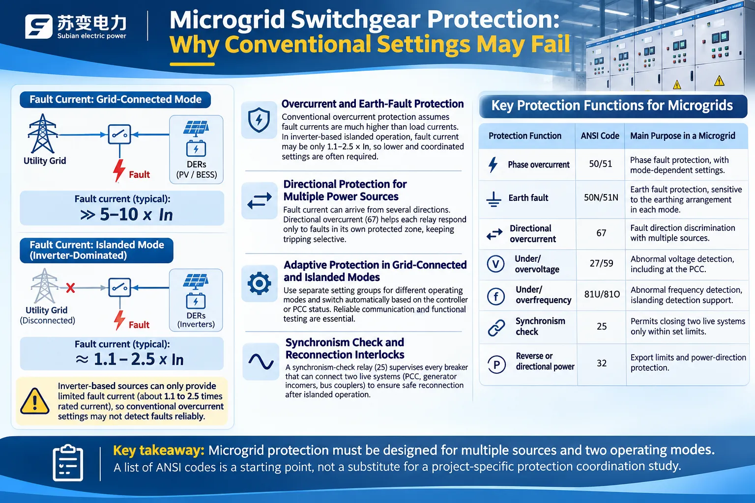
Regular overcurrent relay systems rely on the idea that faults create currents much greater than normal loads, and this applies for grid-connected systems. However, when it comes to islanding systems using only inverters, this may not be true. Research carried out at Sandia National Laboratories has revealed that inverter technology typically has limitations yielding between about 1.1 to 2.5 times rated current during faults and therefore regular overcurrent protection systems may not operate in a microgrid where inverter-based generation is widely used (Sandia, Multiple-Inverter Microgrid Experimental Fault Testing). It is difficult to differentiate between fault current and load currents when the fault current is marginally higher than the load current.
Directional Protection for Multiple Power Sources
With sources on several feeders, fault current can arrive from more than one direction. Non-directional relays may then trip a healthy feeder. Directional overcurrent protection lets each relay respond only to faults in its own protected zone, which keeps tripping selective.
Adaptive Protection in Grid-Connected and Islanded Modes
Due to the fact that the fault level in both operating modes differs significantly, many microgrids rely on adaptive protection, wherein each protective relay contains separate setting groups. The selection of the active group is based on the status of the controller or PCC breaker, making it necessary to use lower pick-up values during the island operating mode. Communication must be reliable in adaptive schemes and must be confirmed during the commissioning process.
Synchronism Check and Reconnection Interlocks
Synchronism-check relays supervise every breaker that can connect two live systems: the PCC, generator incomers and, in some designs, bus couplers.
| Protection function | ANSI code | Main purpose in a microgrid |
| Phase overcurrent | 50/51 | Phase fault protection, with mode-dependent settings |
| Earth fault | 50N/51N | Earth fault protection, sensitive to the earthing arrangement in each mode |
| Directional overcurrent | 67 | Fault direction discrimination with multiple sources |
| Under/overvoltage | 27/59 | Abnormal voltage detection, including at the PCC |
| Under/overfrequency | 81U/81O | Abnormal frequency detection, islanding detection support |
| Synchronism check | 25 | Permits closing two live systems only within set limits |
| Reverse or directional power | 32 | Export limits and power-direction protection |
Which microgrid protection relay functions are needed, how they are set and whether they can detect low fault currents must come from a protection coordination study for the specific system. A list of ANSI codes is a starting point for the study, not a substitute for it.
Microgrid Switchgear vs ATS vs Ring Main Unit
Automatic Transfer Switch for Backup Supply
A transfer switch automatically transfers electricity from the regular source to the backup source and vice versa. It connects one load bus to two sources, but it does not manage PV generation, storage, or export to the electric grid. It is possible to integrate a microgrid transfer switch operation into a microgrid; therefore, an ATS cannot be called a microgrid itself.
RMU for Medium-Voltage Distribution
A ring main unit switches and isolates MV ring feeders and protects distribution transformers, usually with load-break switches and fuses or small circuit breakers. This unit excels at what it does but is not designed for multi-source coordination or adaptive protection.
Microgrid Switchgear for Multi-Source Coordination
| Feature | ATS | Ring main unit | Microgrid switchgear |
| Main job | Transfer a load between two sources | MV ring switching and transformer protection | Connect, isolate and protect several sources and loads |
| Number of sources | Two | Usually one upstream network | Several, including grid, PV, BESS and generators |
| Islanding with export control | No | No | Yes, under a microgrid controller |
| Protection | Basic | Fuses or breaker relays | Coordinated, often adaptive and directional |
The three are not mutually exclusive. One project may use RMUs on its MV ring, ATSs for small life-safety loads and microgrid switchgear at the main bus.
Siemens, Schneider and Eaton: Microgrid Switching Architectures
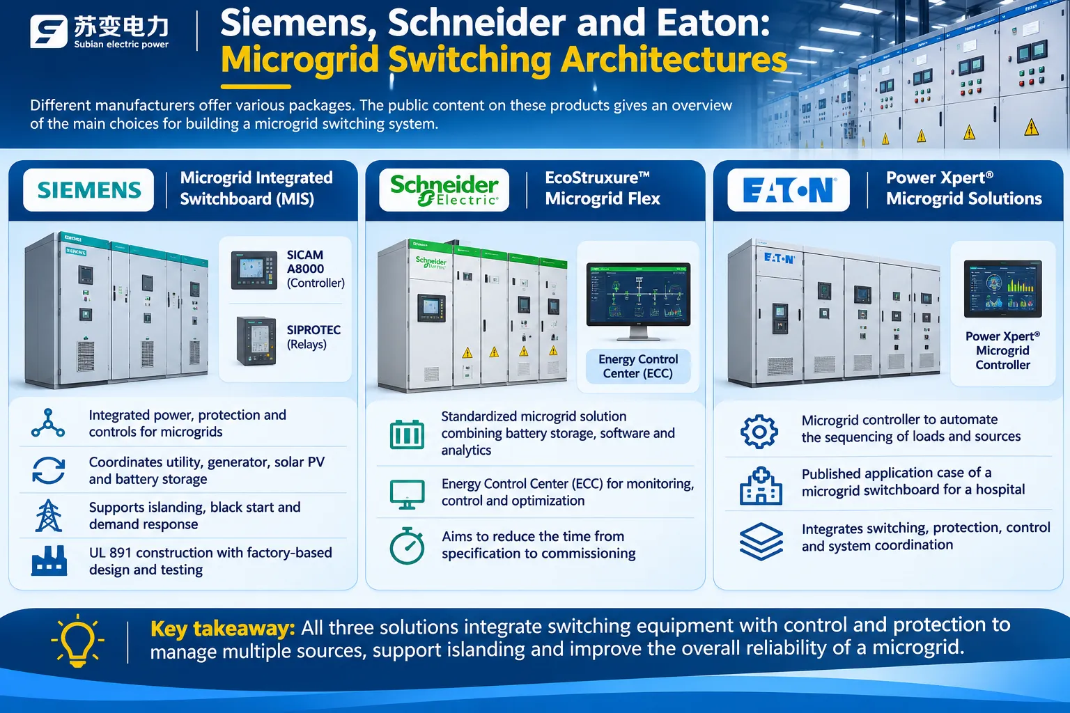
Different manufacturers offer various packages. The public content on this product gives an overview of the various choices for its construction.
Siemens Microgrid Integrated Switchboards
On October 29, 2026, Siemens launched its Microgrid Integrated Switchboard (MIS) that has the integrated functions of power, protection, and controls of microgrid. The system employs a SICAM A8000 controller, SIPROTEC relay protections, and UL 891 construction in the process. The company claims that it enhances coordination between utility, generator, solar PVs, and battery storage, including islanding, black start, and demand response. He states that the equipment’s design process moves from the construction site to the factory.
Schneider Electric EcoStruxure Microgrid Flex
Schneider Electric EcoStruxure Microgrid Flex is marketed by the company as a standardized solution, which combines battery storage, software, analytics, and Energy Control Center (ECC). It aims at reducing the time period between specification and commissioning.
Eaton Power Xpert Microgrid Solutions
Eaton claims to provide Power Xpert microgrid controller, which assists in automating the sequencing of loads and sources. The company has published its case on the use of microgrid switchboard in the hospital.
Hardware Integration vs Controller-Based Architecture
| Approach | How it works | Strengths | Trade-offs |
| Integrated switchboard | Controller, relays and distribution built and tested as one factory unit | Less site integration, faster commissioning | Best suited to standard configurations |
| Controller-based | Separate controller supervises switchgear from one or more suppliers | Flexible for complex, MV or retrofit sites | More site engineering and integration testing |
Mitsubishi Electric’s Product System of Low-Voltage Switchgear offers an array of options for low voltage switchboard product. Siemens makes use of switchgear configuration made as per IEC specifications, along with the use of a separate controller and relay mechanism whereas the Subian Electric is an independent manufacturer and has no affiliation with Siemens, Schneider Electric or Eaton.
IEC and IEEE Regulations Related to Switchgear in Microgrids
The first one is IEC 61439-2, standard for low-voltage electric power switchgear and control assemblies. These low-voltage switchboards act as the main busbars for a majority of modern microgrids.
The second standard is IEC 62271-200, concerning metal-enclosed AC switchgear for service voltages surpassing 1 kV and reaching up to 52 kV. This standard refers to switchgear for midvoltage microgrids.
The IEEE 2030.7-2017 standard deals with the particularities of operation of the microgrid controllers, focusing on their two major functions: the transition between operating conditions and deployment of microgrid assets.
The last standard, IEEE 2030.8-2018, concentrates on testing the microgrid controllers as to the mentioned above functions.
IEEE 1547-2018 is concerned with interconnections and interoperability of the grid connected distributed energy resources.
These standards are of different levels. A switchboard constructed in compliance with the IEC 61439-2 is not necessarily a microgrid controller, and a microgrid controller compliant with the IEEE 2030.7 standard does not prove the switchgear installed around it is rated correctly. A fully-fledged microgrid requires compliant equipment of all levels and a system test.
Microgrid Switchgear for Solar, BESS and Industrial Applications
Solar PV with Battery Energy Storage Microgrids
Solar PV and Battery Energy Storage Microgrids rely heavily on the inverter, meaning that in island mode, the Battery Energy Storage System (BESS) acts as the grid’s energy source while only the occurrence of fault current poses challenges for protection. Equipment used in the BESS must also cope with the flow of energy both ways through the feeder circuit breaker.
Industrial Settings and Essential Loads
Facilities with heavy machinery will need to have switchgear and energy generation standards suited for the loads during motor operation in island mode. Cutting out loads helps to ensure loads are able to operate despite changes that may occur.
Remote Areas and Off-the-Grid Power Systems
If there is a lack of connection to the local utility grid, the system would stay in the island mode. Even though the point of common coupling (PCC) goes away, protection devices and the dispatching program will still be in use.
Commercial and Campus Microgrids
Hospitals, IT facilities, universities and universities may have their own energy supply systems in the form of local renewable energy production facilities, Battery Energy Storage Systems (BESS), and generators to enable uninterrupted system operation.
How to Specify Microgrid Switchgear for an EPC Project
Voltage, Busbar Current and Short-Circuit Ratings
In determining the rating for the busbars, the maximum combined output from all the sources must be evaluated and not just the output from the utility.
The rating for short-circuit withstand must also be made known to what is considered the worst-case scenario, which is most probably when all the machines in operation are connected to the utility.
Number of Incoming Sources and Breaker Configuration
For every source of power and every load group that must be turned on or off by the controller, the number of circuit breakers must be determined. Also, an allowance must be made for future additions of photovoltaic or other storage systems in the system design.
Make a decision on whether a bus coupler is necessary for separating critical loads.
Protection Relay and Communication Requirements
The functions of the protection relays, setting groups for each operational mode and communication methods from the protection relays to the controller and SCADA such as IEC 61850 or Modbus must be defined in the project control design.
Interlocking, Testing and Commissioning
The project control design must define and establish the electrical and mechanical interlocks in the PCC, generator and bus coupler circuit breakers. Also the factory acceptance tests and site tests for each transitional state: connecting to the grid, islanding and black start, must be specified.
RFQ Checklist for Microgrid Switchgear Suppliers
| Item | What to provide or specify |
| System single-line diagram | All sources, loads, transformers and PCC location |
| Voltage and frequency | Nominal voltage, highest voltage for equipment, 50 or 60 Hz |
| Sources | Type and rating of each source: utility, PV, BESS, generator; which is grid-forming |
| Ratings | Busbar current, short-circuit withstand, breaker ratings for each way |
| Earthing | System earthing in grid-connected and islanded modes |
| Protection | Relay functions, setting groups, results of the coordination study |
| Controls and communication | Controller scope and supplier, protocols, SCADA interface |
| Operating sequences | Islanding, reconnection, load shedding and black start logic |
| Standards and tests | IEC 61439-2 or IEC 62271-200, factory and site acceptance criteria |
| Environment and enclosure | Indoor or outdoor, IP rating, ambient range, altitude |
Medium-Voltage and Low-Voltage Switchgear from Subian Electric
Subian Electric manufactures the switchgear hardware that forms the backbone of an IEC-based microgrid: the incomers, feeders, bus sections and protection compartments. Controllers and protection schemes are specified for each project with the system integrator.
KYN28A-12 for MV Feeder and Breaker Applications
The KYN28A-12 withdrawable metal-enclosed switchgear is a 12 kV, 50 Hz metal-clad design with withdrawable vacuum circuit breakers and five-prevention interlocking. In an MV microgrid it suits the PCC incomer, generator and BESS incomers, and outgoing feeders, with the relay scheme configured for each project. It can be paired with Subian’s VS1 indoor vacuum circuit breaker. Where an MV ring distributes power around a site, the HXGN15-12 ring main unit can serve the transformer feeders.
GCS and MNS for LV Distribution Systems
For low-voltage microgrids, the GCS low-voltage draw-out switchgear (380/660 V, up to 4000 A) and the MNS low-voltage draw-out switchgear (380/660 V, up to 6300 A) are built to IEC 61439 and GB 7251. Their draw-out functional units make it practical to allocate separate ways to utility, PV, BESS, generator and critical-load circuits.
Engineering Interfaces for Microgrid Integration
Where sources connect at MV, Subian’s YB series prefabricated substation combines the transformer with MV and LV equipment in one enclosure. For each project, Subian builds the switchgear to the approved single-line diagram, with breaker compartments, CT and VT provisions, auxiliary wiring and interlocks prepared for the protection relays and controller specified by the system designer. The broader range is listed under high and low voltage switchgear.
Frequently Asked Questions
What is microgrid switchgear?
The scaling and insulating switches and protection devices of LV and MV type connect power sources and load points of the microgrid which are under control of the microgrid manager.
How does microgrid switchgear work?
Breakers link every source and load group to a common bus. Faulty conditions are cleared by relays, while the controller opens the PCC breaker, in cases of grid failure, operates local sources in island mode, and reconnects them to the grid after synchronizing.
Can a microgrid operate without the utility grid?
Yes, it’s true if it possesses a source that can determine voltage and frequency – for example, a generator or grid-forming battery inverter – sufficient power level to allow for the critical loads, and protection that copes with the island fault levels.
What is the difference between microgrid switchgear and an ATS?
An ATS transfers one load between two sources. Microgrid switchgear coordinates several sources and loads, controls export to the grid and supports islanding and reconnection under a controller.
How does microgrid protection change during islanding?
Fault current usually drops, sometimes to only 1.1 to 2.5 times rated current from inverter sources, so relays often switch to more sensitive setting groups and rely more on directional, voltage and frequency functions.
Does a microgrid need a grid-forming inverter?
It needs a grid-forming source to operate as an island. That can be a grid-forming inverter, usually on a BESS, or a synchronous generator. Grid-following PV inverters cannot form an island alone.
What is the point of common coupling in a microgrid?
It is the point where the microgrid connects to the utility network. The PCC breaker opens to form an island and closes to reconnect, under utility-approved protection and synchronization controls.
What standards apply to microgrid switchgear?
IEC 61439-2 for LV assemblies, IEC 62271-200 for MV metal-enclosed switchgear, IEEE 2030.7 and 2030.8 for microgrid controllers and their testing, and IEEE 1547 for interconnecting distributed energy resources.
References
- U.S. Department of Energy: The U.S. Department of Energy’s Microgrid Initiative (Ton and Smith)
- Sandia National Laboratories: Multiple-Inverter Microgrid Experimental Fault Testing
- NREL: Highlights of IEEE Standard 1547-2018
- IEEE 2030.7-2017 Standard for the Specification of Microgrid Controllers
- IEEE 2030.8-2018 Standard for the Testing of Microgrid Controllers
- IEC 61439-2:2020 Power switchgear and controlgear assemblies
- IEC 62271-200:2021 AC metal-enclosed switchgear above 1 kV and up to 52 kV
Conclusion
Microgrid switchgear is determined by its functioning rather than by its physical form; it should be able to transmit electricity from various sources in both directions, safely disconnect from the grid when needed, feed insufficiently supplied critical applications when isolated from the grid, and then reconnect to it following safety standards. The operation follows from the existence of a grid-forming energy source, a protective device that does not switch off due to the inverter limits, and a controller.
Key points to be noted:
The PCC circuit breaker defines the operation of the island, while everything else depends on its protection and control means.
The island should be provided with a grid-forming energy source; circuit breakers are not enough for this.
Inverter current at the moment of failure does not exceed 1.1 – 2.5 from its nominal current; thus the microgrid protection should have special settings depending on the operation mode and should be verified through some coordination study.
An ATS, an RMU, and a microgrid switchgear serve different purposes but can be used in the same project.
Speak about the LV and MV microgrid separately, ensuring that the ratings, operational procedures, and testing criteria are provided in the RFQ.
Subian Electric is a reliable partner for designing microgrid switchgear according to your connection diagrams, contact Subian Electric if there is a list of the energy sources, voltage level, and protection requirements. The engineering department will approve the design and send you the drawings and a quote for the switchgear.