


A single line diagram is arguably the most essential drawing but also most frequently ignored drawing in a substation. Although it does not function as a construction diagram and is not drawn to scale, it conveniently conceals two out of three phases. Nonetheless, every short-circuit study, every protection setting, every switchgear log, and every Arc Flash label traces back to the single line diagram. Any mistakes or delays in updating it lead to subsequent mistakes in all other related documents.
The single-line diagram is, indeed, the most important but often neglected drawing in a substation. It is not a construction diagram nor is it produced to scale, yet it hides two-thirds of the phases easily. Regardless of this fact, every short-circuit study, protection setting, switchgear log, and Arc Flash label can be traced back to the single-line diagram. Any errors and omissions related to updating can result in mistakes in all related documents, too.
What an SLD Is, and What It Is Not
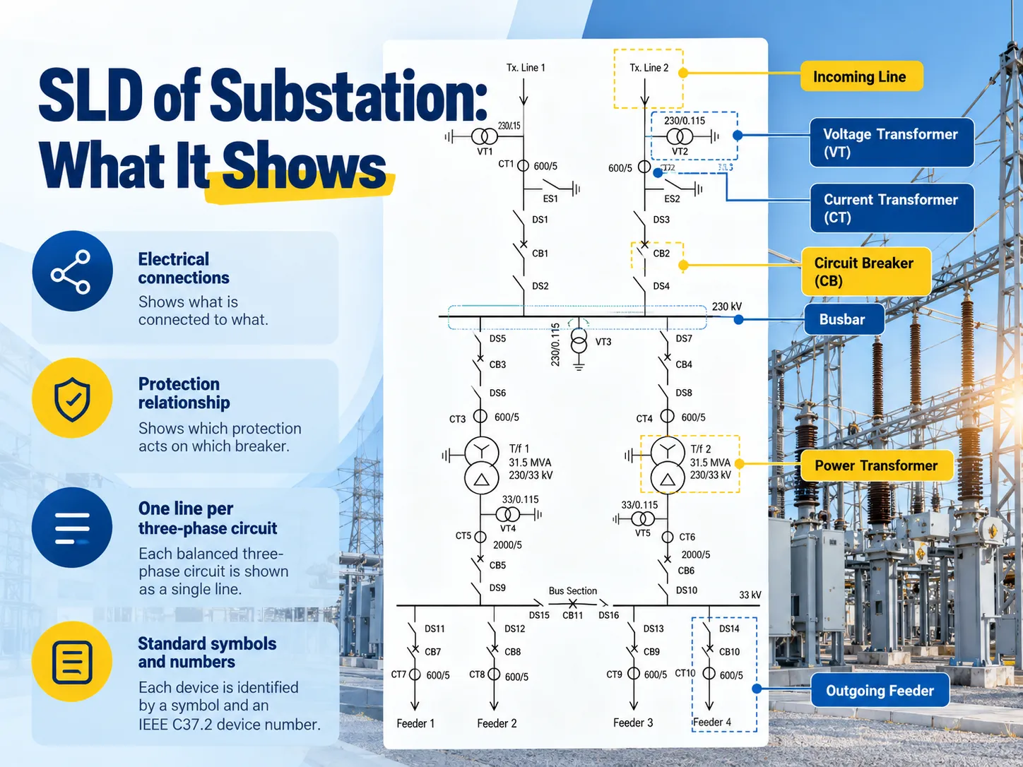
A single line diagram, also known as an SLD, is a diagram in which three-phase power systems are represented by one line for each electrical power connection. Because the electrical machines are built the same way for two phases, they can use one configuration not just for one phase but for all three at the same time. The symbols used in the SLD determine what machine upgrade is employed at each point in the SLD. In order to be flexible, the SLD adheres to a number of specified rules. In North America, it means using symbols composed through IEEE Standard 315; in other parts of the world, the use of IEC 60617 symbols is recommended.
The devices are represented by their positions in the SLD, whereas the priorities of the electrical installations are depicted in other types of drawings. It means that wherever both arrangements cannot be shown, the electrical arrangement will be displayed.
The distinction between a one-line diagram as a study tool and as a construction document is worth holding onto, because US practice draws a firmer line between the two than most IEC markets do, as this explanation of a unifilar (single-line) diagram in US utility and industrial practice sets out.
What Every SLD Has to Show
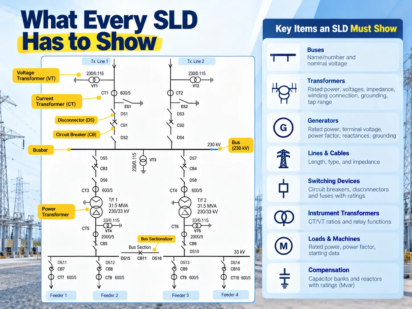
An SLD is complete only if it includes all required details. Leaving anything out will not allow the SLD to serve its purpose of functioning with studies it was designed for:
- Buses, containing name or number and nominal voltage. The representation will look as a thick line.
- Transformers, where you need rated power and voltages, impedance in percentage, connection (delta or wye), grounding, and tapping range, along with likeness of windings.
- Generators, the information that has to be given includes rated power, terminal voltage, power factor, reactances, and neutral grounding.
- Lines and cables: length, conductor or cable type, and impedance.
- Switching devices: circuit breakers, disconnectors, and fusible switches along with their ratings and positions.
- Instrument transformers, with ratios of current and voltage transformers and which functions of relay these transformers feed.
- Loads and machinery: rated power, power factor, and initial data on starting in case of big motors.
- Compensation: capacitor bank and reactors with their Mvars ratings.
This list is also the reason for conversion of SLD into per-unit impedance scheme for studies. Every component will be replaced by its equivalent in per-unit based on chosen system base and the resultant system is what load flow or short circuit software will solve.
Reading the Symbols
Tuning into the visual language is a simple job after picking up the basics. A machine in rotation appears as a circle with a symbol next to the letter: G for generator, M for motor. A transformer with two coils appears as two coiled circles, or, in a number of North American diagrams as two opposite coiling symbols with delta or wye symbols next to it and ground symbol nearby any ongoing ground product. Busbars appear as thick lines with more light lines around them indicating outgoing circuits. A circuit breaker appears as a small square in the ANSI tradition, while in IEC schematics it can be depicted as the contract symbol with a specific word. The disconnector works like an open blade because, unlike a circuit breaker, it is not graded for the job and is typically used when there is no energy. Fuses are depicted as zigzags or rectangles on drawing lines.
The very first thing, which is always made incorrectly while reading an SLD for the very first time, is confusing two devices in vicinity with each other. A circuit breaker and disconnector in series may look alike but provide completely different services: a circuit breaker actually interrupts short circuits while disconnector provides visible isolation. The maintenance practice, which confuses one with the other, is the very reason for accidents.
Device Numbers and the IEC 61850 Equivalents
The numbers in little circles next to current transformers indicate the functions of these protections even before referring to any key. In compliance with IEEE C37.2-2022, 95 device function numbers and 22 acronyms are valid, and normally you will encounter the following:
- 52 — AC circuit breaker (it excludes the relay itself)
- 50 / 51 — instantaneous overcurrent / time overcurrent
- 87 / 87T / 87B — differential protection, transformer differential protection, bus differential protection
- 27 / 59 — undervoltage / overvoltage
- 25 — synchronism checking
- 79 — automatic reclosing
- 86 — out of service relay
The letters at the end of the numbers narrow down the function to a certain form, for example, 51P-1 is the first step in phase time overcurrent function. IEC uses different designations for the same functions. For example, IEC 60617 uses simple symbols for quantity and comparison, such as I> for overcurrent. IEC 61850 defines each function as an instance of logical nodes, for example, PTOC for time overcurrent. Relay producers use all of the three designations so that customers can find the definitions of the relays using any of the three standards. For instance, the manual for ABB REF615 feeder relay gives its low-stage three-phase non-directional overcurrent relay the designations of PHLPTOC according to IEC 61850, 3I> according to IEC 60617, 51P-1 in IEC-ANSI.
In the picture, only the secondary circuits of the transformers are shown in their simplified version, that is, only the polarities of the voltages are drawn without their return paths. This makes it easier to read the circuit.The devices hanging off those circuits — relays, meters, transducers — get the circling. An installation that follows that discipline end to end, from the 10 kV indoor current transformers that supply the relay circuits through to the relay panels they terminate on, is a site where the SLD stays useful for decades instead of becoming a historical document.
The Three Diagrams a Substation Actually Needs
A standard system can produce numerous one-line diagrams, each made for a specific purpose, and mixing them leads to serious complications:
- Study diagram shows the substation reduced to buses and links between them for its solution by load flow or short circuit software.
- Operating diagram depicts all circuit breakers and isolators in node-breaker configuration, as the operator must understand which breaker powers the which cell and that all devices illustrated are normally in their default mode, which makes it easy to spot a bus tie which is normally open.
- Protection diagram shows CT and VT positions along with relay functions that they fulfill as well as circuit breakers that any relay trips.
In situations where something cannot be clearly indicated in one-line diagram — polarity of current transformer, connection of measuring devices — a three-line diagram showing neutral along with all three phases is used, which is rather an exception and not a general practice.
Busbar Arrangements and What They Tell You
The design of busbars in a schematic representation of a power system reflects both its efficiency and price. Hence, it is usually the first thing that a skilled specialist considers:
- Single bus – the simplest and cheapest solution. Any failure or repair of a busbar will lead to a bus outage and shutdown of the entire circuit connected to that busbar. This design works well for minor distribution stations, but is unacceptable in the case of more vital power delivery.
- Double bus – single or double breaker. A second busbar installation helps in transferring loads; the double-breaker method allows operations on the busbar without needing the bus to be out, which, however, increases costs.
- Ring bus – an arrangement of the bus system in a circle, with all the circuits fed with electricity from two sides. In this case, any outage of a circuit breaker can be easily repaired.
- Breaker-and-a-half – three circuit breakers for only two circuits, leaving it possible for all loads to stay powered even if a bus or a breaker malfunctions. It is a standard solution for important electrical systems.
- Main and transfer busbar – this involves an additional busbar and a transfer circuit breaker, so it is possible to turn off the circuit breaker while the line remains on.
Examining bus bar configurations is the quickest way to determine how much outage resistance a system has, which explains the huge difference in cost between similar substations. The wider equipment question — what a complete station needs and what it costs — is covered in this review of what a complete substation package actually includes for international buyers.
Bays, Switchgear and the Boundary of the Diagram
The SLD has different categories of bays including incoming line bays, transformer bays, bus coupler or bus section bays, feeder bays, and capacitor or reactor bays. Every bay is a unit that has its own breaker and disconnectors, VTs, CTs, and earth switch, while depending on the position of the SLD on the page, each bay is read from one end to the other.
What appears on the SLD as symbols integrated into a bay actually represents considerable amount of actual equipment. In the majority of cases on the medium voltage air insulated switchgear applications, the bay looks like a withdrawable unit encased in metal and the physical layout of the symbols makes a difference between the pictorial representation and real equipment designated in the specification. A 12 kV withdrawable metal-enclosed switchgear assembly is the hardware that a typical single-bus or double-bus SLD bay resolves into on site. Two bays on the drawing, one enclosure in reality.
GIS and IEC 61850: Two Things That Change the Drawing
In the last ten years, two things have changed how SLDs are made.
The first is the emergence of gas-insulated switchgear. Unlike AIS where breakers, disconnectors and earth switch are drawn separately in the diagram (because equipment is located in the open), a GIS bay is usually represented as a single block since all equipment is in a sealed enclosure. If you happen to come across a drawing showing GIS layout according to AIS principles, it is a legacy drawing or simply a mistake.
The second development is IEC 61850 and process bus. In the case of the merging unit, the analogue signals are digitised and transmitted over the fibre, while the physical connection does not indicate which analogue input is being used by the intelligent electronic device (IED). The direct correlation of CT and relay input becomes a set of data the system can possibly use rather than a direct connection.
IEC 61850 also allowed for creation of machine-readable drawings. The single line diagram is now transformed into data since Substation Configuration Language specified in IEC 61850-6 can describe the SLD and its components in data form.
How to Prepare an SLD
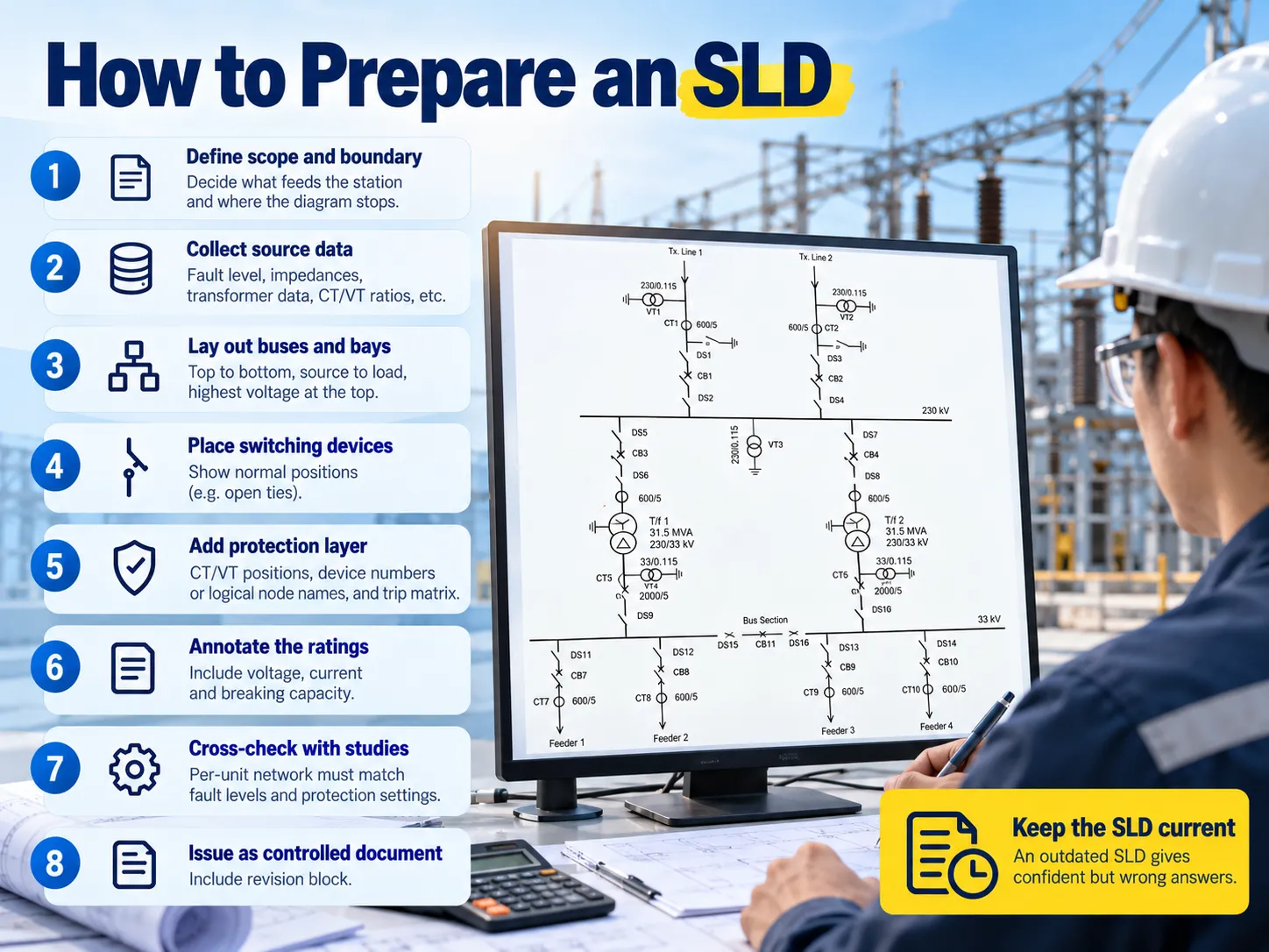
Let’s be realistic: the process is dull and sequence is important:
- Set the project limits. Specify the source of energy and the endpoint of the diagram. After that no one will oppose to your conclusion.
- Gather the information about the source used. This includes its fault level, connection point, impedance, information about the transformers used including its tap range and vector group, information about the CTs and VTs used in connection.
- Put out the diagram vertically with sources on the top and loads at the bottom of it.
- Position the switches. The open switches as ties must be marked as those without being buried in the notes.
- Add the devices to the electrical diagram. Include the CT and VT position, numbers of devices or IEC 61850 names and the trip matrix.
- Mark down the power ratings. Just a circuit breaker without the parameters is meaningless.
- Double check the data with the real studies conducted and compare it with the SLD. If it doesn’t agree it means that either the conclusion is wrong or the study itself is wrong.
- Print it like a controlled document with a revision box. An SLD without control ceases to be valid and reliable within a period of one year.
Why a Stale SLD Is Worse Than No SLD
A design based on an obsolete diagram gives reliably erroneous results. All circuit studies and arc flash calculations begin with the one-line diagram, and this diagram is a part of any arc flash report and is important for a worksite. This means an outdated diagram gets directly translated into equipment ratings, PPE types and setting of protective devices. The problem is not “we do not know” but “we think we know but the number is wrong”.
That is why the one-line diagram earns its money twice — first when equipment is designed and second when someone works with the equipment. Keeping the one-line diagram updated is a job that requires housekeeping rather than engineering and is usually the first thing to forget about.
FAQ
What is substation SLD?
SLD of the substation refers to the alphabetical diagram that displays the electrical connection and insulation of the power system equipment. All three-phase circuits in the diagram are represented by one single line. Each apparatus in the diagram is shown by a symbolic language with numbers designating its types.
What is the meaning of SLD in electrical?
A single line diagram, often referred to as a one-line diagram or unifilar diagram, gets its name from the representation of the three phases of power equipment in a single line. In IEC markets, drawing rules are derived from IEC 61082-1, while symbols are taken from IEC 60617 or IEEE Std 315 in North America, respectively.
What is a SLD in construction?
In construction applications, the single line diagram is the document that defines the electrical scope: which feeders are available, what takes care of them, and what values are used. Contractors use it for pricing the switchgear and cable schedule; and commissioning teams use it for establishing the switching program and checking if the equipment provided is in line with the design.
How to prepare SLD?
In construction work, the single line diagram gives information regarding the electrical elements such as what has been powered, what is powering it, and how. The contractors utilize this document when pricing the switchgear and cable schedule, while the commissioning teams follow it for establishing the switching program and seeing if the provided equipment corresponds to the design.
References
- Electrical Engineering Portal — Understanding substation single line diagrams and the IEC 61850 process bus
- SEL (Schweitzer Engineering Laboratories) — protection application guides and device function numbering in practice
- Hitachi Energy — substation automation, IEC 61850 systems and switchgear portfolio documentation
- Siemens Energy — high-voltage substation and digital substation reference material
- GE Vernova — grid solutions documentation on protection schemes and substation design
- Mitsubishi Electric — power distribution and substation equipment technical publications
- NFPA — NFPA 70E, which requires an up-to-date one-line diagram for arc-flash documentation
- International Electrotechnical Commission — IEC 61082-1, IEC 60617, IEC 81346 and IEC 61850-6
Conclusion
The single line diagram of a substation is a somewhat small diagram with a big function. It specifies the connections, which relay activates which breaker, and what ratings apply, and much depends on it being correct and up-to-date: everything from the fault study to the operation plan relies on it. Read it, as is, pay attention to the numbers assigned to the devices, and treat modification as part of the diagram and not an addition.For retrofit and extension work, the same discipline applies from the first site survey, which is the approach behind utility grid substation upgrade projects that start from an existing arrangement.