


Al observar la factura de servicios públicos y el registro de fiabilidad de producción, el ingeniero de instalaciones se encuentra atrapado en una situación donde una planta opera las 24 horas, consumiendo un pico de energía de 1.8 MW y sufriendo tres pérdidas de producción (debido a desconexiones por bajo voltaje) durante este año fiscal hasta ahora. Una empresa de servicios públicos propone un suministro dedicado de una red de 33 kV que requerirá la instalación de un transformador en la entrada. Uno de los representantes de ventas ha afirmado que un transformador de 2,000 kVA debería ser adecuado para las necesidades de la planta. El ingeniero es consciente de que “debería” no significa dimensionar un transformador correctamente y un consumo de kVA incorrecto llevaría a gastos a largo plazo y una relación de voltaje incorrecta neutralizaría cualquier beneficio de la instalación del transformador propuesta. Por lo tanto, ella requiere un sistema para seleccionar un transformador lleno de aceite correcto.
Esta guía del comprador sirve como el sistema requerido. Guía a través de una serie de las ocho decisiones que definen el proceso de selección de transformadores, como la selección de kVA, la determinación de la relación de voltaje, los parámetros y características de un transformador, el rango de tomas, el nivel de pérdidas y muchos otros con todos los números y estándares respectivos.
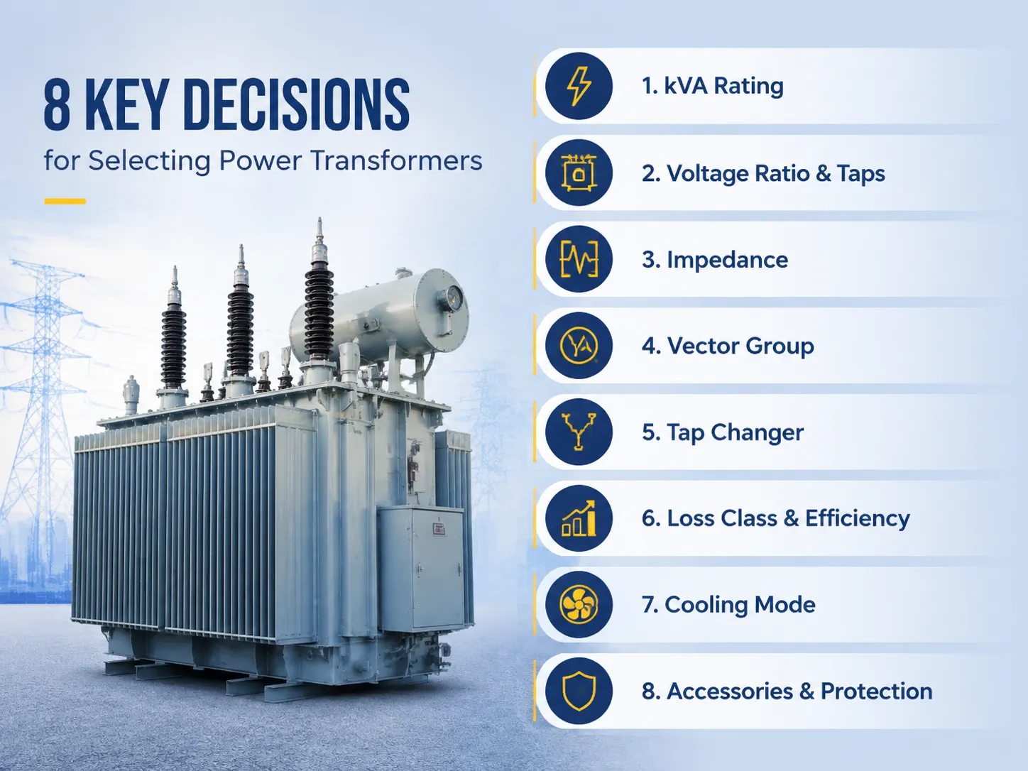
En resumen, al seleccionar un transformador lleno de aceite, entran en juego ocho variables importantes: (1) el tamaño de kVA debe tener en cuenta los picos máximos más un margen del 15-25 por ciento; (2) las relaciones de voltaje deben alinearse con la línea del proveedor de servicios y la del planificador; (3) la impedancia está frecuentemente en el rango del 4.5-8 por ciento basado en la clase y la coordinación del nivel de falla; (4) los grupos vectoriales deben estar sincronizados con la puesta a tierra del sistema y el grado de fase; (5) el rango de tomas se establece en ±2 veces 2.5 por ciento fuera de circuito para redes estables o ±8 veces 1.25 por ciento en circuito para redes débiles; (6) la clase de pérdidas del transformador se establece de acuerdo con GB 20052 o EU Ecodesign capitalizando las pérdidas; (7) la refrigeración debe elegirse entre ONAN o ONAF según el factor de carga; y (8) el equipo opcional incluye relé Buchholz, PRD, monitor de temperatura y vibrotermómetro.
Tabla de Contenidos
- Decisión 1: Dimensionamiento de la Calificación de kVA
- Decisión 2: Relación de Voltaje y Tomas
- Decisión 3: Impedancia
- Decisión 4: Grupo Vectorial
- Decisión 5: Elección del Cambiador de Tomas
- Decisión 6: Clase de Pérdidas y Eficiencia
- Decisión 7: Modo de Refrigeración
- Decisión 8: Accesorios y Protección
- El Método de Selección en Seis Pasos
- Marcas y Orientación de Precios
- Preguntas Frecuentes
- Referencias
- Conclusión
Decisión 1: Dimensionamiento de la Calificación de kVA
La decisión que guía a todas las demás es el dimensionamiento, porque cada decisión posterior se toma en el contexto de un sobre de calificación. La forma correcta:
- Determinar o evaluar la demanda máxima. Utilizar datos de medición de un año (por ejemplo, estudio de carga) o, en caso de que el sitio sea nuevo, determinar la carga conectada y aplicar un factor de diversidad (475 para carga comercial y 0.5-0.8 para carga industrial).
- Convertir a kVA. kVA = kW/factor de potencia. Para un factor de potencia igual a 0.9, la demanda máxima de 1.8 MW se convierte en 2,000 kVA; con un factor de potencia de 0.8 – en 2,250 kVA.
- Siempre utilizar el factor de potencia real o previsto, no 1.0.
- Introducir el margen de crecimiento. Agregar 15-25% para el crecimiento de carga durante el horizonte de planificación de 5-10 años. Por ejemplo, 2,000 kVA se convierte en 2,300-2,500 kVA.
- Redondear a la clasificación estándar. Los incrementos estándar de kVA en esta área son 1600/2000/2500 y 3150.
| kVA calculado (estudio de carga) | Clasificación estándar para ordenar | Aplicación típica |
|---|---|---|
| Hasta 400 kVA | 400 / 500 kVA | Pequeña comercial, pueblos |
| 400–800 kVA | 630 / 800 / 1,000 kVA | Fábricas, centros comerciales |
| 800–1,300 kVA | 1,000 / 1,250 / 1,600 kVA | Industria media |
| 1,300–2,200 kVA | 2,000 / 2,500 kVA | Grandes plantas, campus |
| Más de 2,200 kVA | 3,150 kVA y más | Subestaciones, industria pesada |
Elegir la clasificación apropiada más cercana que supere el valor calculado. Para este caso, el valor inferido en nuestro caso fue 2,500 kVA.
Dos errores comunes de dimensionamiento son costosos. Sobredimensionar (por ejemplo, usar una unidad de 3,150 kVA para una necesidad de 2,000 kVA) causa gastos innecesarios con pérdidas en vacío incurridas durante la vida útil de la unidad: la pérdida en vacío de una unidad de 3,150 kVA (de aproximadamente 4.4) es igual a $3100 por año a $0.08 por kWh. Subdimensionar causa operación en sobrecarga, lleva al envejecimiento del aislante y provoca interrupciones en los picos. El tamaño correcto se define por el estudio de carga, no por el número redondeado del distribuidor.
Decisión 2: Relación de Voltaje y Tomas
La relación de voltaje debe ser igual en ambos extremos del sistema: el voltaje de la utilidad y el voltaje en el bus. Las parejas más comunes se indican a continuación:
| Voltaje de alimentación | Bus del lado de carga | Unidad típica |
|---|---|---|
| 33 kV | 11 kV | Distribución 33/11 kV |
| 35 kV | 5 kV | Potencia 35/10.5 kV |
| 22 kV | 11 kV | Distribución 22/11 kV |
| 11 kV | 4 kV | 11/0.4 kV montado en poste o base |
| 6 / 6.3 kV | 4 kV | 3/0.4 kV industrial |
El rango de los tomas se determina en el lado de alta tensión y compensa tanto el cambio de voltaje de la utilidad como la caída de voltaje del transformador. El caso cuando el suministro de voltaje es constante con una precisión de ±2.5% se puede realizar utilizando tomas fuera de circuito con posición ±2 × 2.5%. En situaciones cuando el suministro es débil y/o la carga cambia, un cambiador de tomas bajo carga con regulación de ±8 × 1.25% mantiene el control necesario. Hablando económicamente, el OLTC aumenta el costo del transformador en un 15-30%, lo cual es razonable solo cuando realmente hay cambios en el voltaje.
Decisión 3: Impedancia
El factor de impedancia (voltaje de cortocircuito, UK%) determina dos factores que pueden estar en conflicto entre sí: características regulatorias de voltaje y corriente de cortocircuito. La menor degradación está asociada con una regulación más fuerte, pero al mismo tiempo da lugar a una mayor corriente de cortocircuito. Por otro lado, cuanto mayor sea la impedancia, menor será la corriente de cortocircuito, pero la caída de voltaje será mayor. La regla general es implementar el transformador que sea compatible con el equipo de protección y conmutación ya en uso:
- Transformadores de distribución (≤1,000 kVA): 4 – 4.5% es la norma;
- Transformadores medianos (1,6 – 10 MVA): 6% – 8% es el promedio; 7.5% es una especificación común;
- Transformadores pesados (>10 MVA): 8% – 14%, cuanto mayor sea la potencia, mayor será la impedancia.
La impedancia inapropiada puede ser un peligro de coordinación. Si la impedancia elegida es demasiado pequeña, el transformador proporcionará la corriente de cortocircuito que estará más allá de la capacidad del interruptor automático para despejar.
Decisión 4: Grupo Vectorial
La definición del grupo vectorial abarca la configuración de bobinado y el desplazamiento de fase del transformador, así como su configuración de puesta a tierra y los requisitos de operación en paralelo. Dos de los grupos vectoriales más comunes utilizados en transformadores sumergidos en aceite son:
- Dyn11: Configuración delta en el lado alto y configuración estrella en el lado bajo (con el conductor neutro del transformador). Esta designación de grupo vectorial se utiliza normalmente para transformadores de distribución (por ejemplo, 11/0.4 kV) que operan en circuitos monofásicos o trifásicos.
- YNd11: Configuración estrella en el lado alto (con el conductor neutro del transformador) y configuración delta en el lado bajo. Esta designación de grupo vectorial es común para transformadores de potencia (por ejemplo, 35/10.5 kV) que alimentan el lado a tierra a través del neutro del transformador.
La importancia del grupo vectorial se hace evidente al paralelizar dos o más unidades. Dos transformadores conectados al mismo bus deben tener el mismo ángulo de desplazamiento de fase, así como impedancias coincidentes iguales a ±7.5%. Si los grupos vectoriales son diferentes, se establecen corrientes circulantes que causan sobrecalentamiento de los transformadores, lo cual es un problema costoso que se puede evitar al verificar la placa de identificación.
Decisión 5: Elección del Cambiador de Tomas
Según los expertos, el cambiador de tomas es la única parte móvil del transformador. La decisión de seleccionar tomas está relacionada con la fiabilidad.
| Tipo | Rango típico | Operación | Impacto en costos | Mantenimiento |
|---|---|---|---|---|
| Fuera de circuito (DETC) | ±2 × 2.5% | Desenergizado solamente | Línea base | Ninguno más allá de la inspección |
| Bajo carga (OLTC), resistor sumergido en aceite | ±8 × 1.25% o ±6 × 1.67% | Bajo carga | +15–30% | 50,000–100,000 ops |
| OLTC, tipo vacío | ±8 × 1.25% | Bajo carga | +20–35% | 150,000–200,000 ops |
Si la fuente de alimentación es estable y la carga es constante, se pueden emplear tomas fuera de circuito. Si se requiere regulación bajo carga, la fuente de alimentación debe variar más de ±2.5% en caso de que la carga sea inestable o el proceso no pueda funcionar debido a eventos de baja tensión. La diferencia de precio ($6,000-12,000) de una unidad de 10 MVA parece insignificante en comparación con la pérdida causada por el caso prolongado de baja tensión.
Decisión 6: Clase de Pérdidas y Eficiencia
La mayoría de los costos de vida se evalúan en la categoría de pérdidas. Dos mediciones de pérdidas comúnmente utilizadas son la pérdida en vacío (P0, continuando todo el día) y la pérdida de carga (Pk, dependiente del cuadrado del factor de carga). Siga las recomendaciones:
- Adhiérase a las normas aplicables: Verifique GB 20052-2020 en China, la Regulación de Ecodesign de la UE 548/2014 en Europa y U.S. DOE 10 CFR Parte 431 porque tienen un límite máximo para pérdidas que es muy útil.
- Valore la diferencia: Cada kW de P0 valdría tarifa × 8,760 h × vida del proyecto. Cada kW de Pk valdría tarifa × 8,760 h × (factor de carga promedio)² × vida del proyecto.
- Seleccione clase de baja pérdida en caso de alto factor de carga: Con valores de P0 60-70% más bajos utilizando transformador de núcleo amorfo, una inversión puede recuperarse en 6-12 años y seguiría generando ganancias.
Algunas estadísticas sobre la unidad de 1,000 kVA: La tecnología de baja pérdida tiene aproximadamente 1.1 kW menos de P0 que S11, lo que equivale a aproximadamente $770/año a $0.08/kWh, $19,000 a pagar durante 25 años frente a $3,000-$6,000 a pagar inicialmente.
| Factor de carga | Pérdida en vacío S11 (1,000 kVA) | Pérdida en vacío amorfa | Ahorro anual @ $0.08/kWh |
|---|---|---|---|
| 3 (ligero) | 7 kW | 6 kW | $770 |
| 6 (promedio) | 7 kW | 6 kW | $770 |
| 9 (pesado / 24/7) | 7 kW | 6 kW | $770 |
La pérdida en vacío permanece similar independientemente del factor de carga. Esto significa que los ahorros se mantienen constantes. Las altas horas de operación aseguran que la inversión en Premium implacable se recupere rápidamente.
Decisión 7: Modo de Refrigeración
Al poner un transformador en modo de enfriamiento, determinará el límite térmico y la sobrecarga permitida. Lo siguiente indica las normas actuales y sus interpretaciones:
- ONAN: El aceite y el aire se utilizan naturalmente para enfriar el transformador. Este es el tipo más básico de enfriamiento, el más simple, silencioso y sin componentes de falla.
- ONAF: Se añaden ventiladores además del aceite para el enfriamiento. Esto aumenta la potencia en un 20 a 30 por ciento con el uso de los ventiladores, que solo es adecuado para sobrecargas o cargas intermitentes.
- OFAF/ODAF: El método de enfriamiento forzado con el uso de ventiladores para los transformadores más grandes – cuando el calor no puede ser eliminado utilizando el enfriamiento por convección natural.
Si su factor de carga es menor que aproximadamente 0.8 y tiene solo unos pocos picos – elija ONAN. Si espera tener sobrecargas a corto plazo con frecuencia – elija ONAN/ONAF: en tal caso, su transformador de distribución de 1,000 kVA podría alcanzar 1,250 kVA con la ayuda de ventiladores. Asegúrese de que el mapa de sobrecarga verifique contra IEC 60076-7.
| Modo de enfriamiento | Calificación base | Margen de sobrecarga a corto plazo | Hardware |
|---|---|---|---|
| ONAN | 100% (placa de identificación) | Típicamente 120–130% durante 1–2 h según IEC 60076-7 | Solo radiadores |
| ONAN/ONAF | 100% con ventiladores apagados | +20–30% con ventiladores encendidos | Radiadores + ventiladores |
| OFAF / ODAF | Clasificación de enfriamiento forzado | Limitado por el punto caliente del devanado | Bombas + ventiladores |
Decisión 8: Accesorios y Protección
La lista de accesorios es breve, es obligatoria en el servicio y frecuentemente es el punto más crucial para diferenciar entre el incidente y la catástrofe:
- Relé Buchholz (gas): Alarma de gas lenta y disparo rápido por oleada de aceite para dispositivos tipo conservador de más de ~1 MVA. Conéctelo y realice las pruebas.
- Dispositivo de alivio de presión: Libera el tanque de la presión interna; dimensionelo de acuerdo con el dispositivo.
- Indicadores de temperatura de aceite y devanados: Con las alarmas y disparos configurados de acuerdo con el presupuesto de aumento de 65K.
- Medidor de nivel de aceite: Un nivel bajo hace que los devanados se abran; verifíquelo durante la revisión trimestral.
- Deshumidificador de gel de sílice: Deshumidifica el aire que entra en el conservador; cambie el gel de sílice si ya está rosa.
- Contención de aceite: Bund o un pozo dimensionado para acomodar el volumen total de aceite, según lo prescrito por la IEC 61936-1 y las regulaciones locales.
Ninguno de estos elementos cuesta mucho en comparación con el dispositivo y, juntos, convierten el transformador sumergido en aceite de una amenaza de incendio a un activo gestionado. Presupuestar 1–3% del precio unitario para todo el conjunto de protección.
El Método de Selección en Seis Pasos
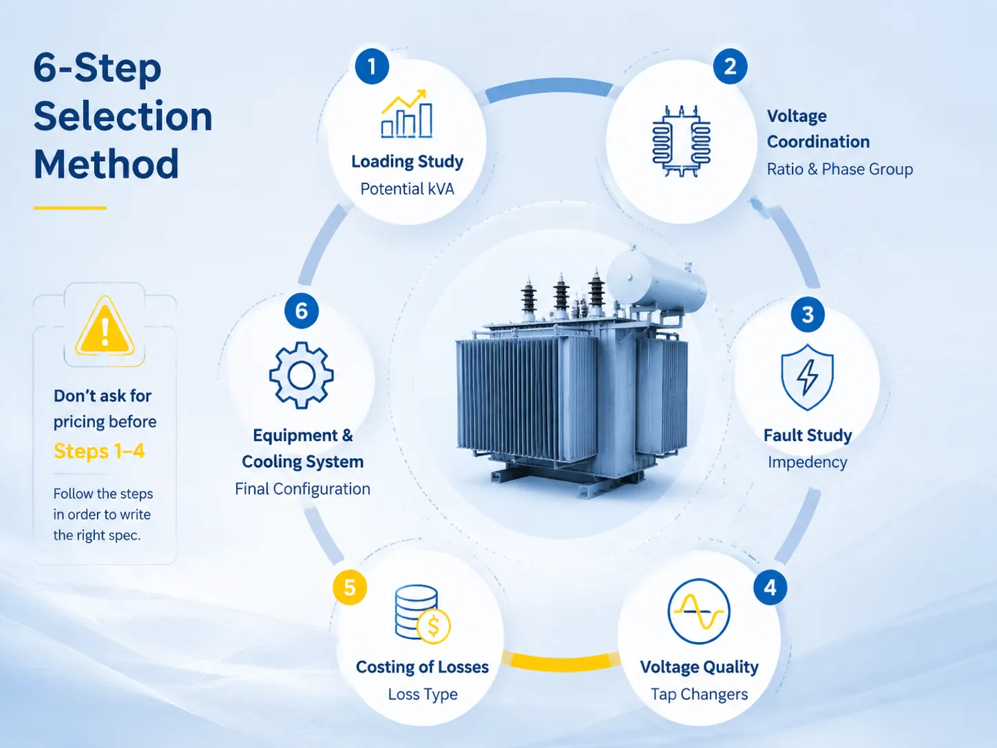
- Estudio de carga: kW máximo, factor de potencia, factor de carga, plan de crecimiento → kVA potencial.
- Coordinación de voltaje: voltaje de suministro, voltaje de bus, puesta a tierra, requisitos de interconexión → relación y grupo de fase.
- Estudio de fallas: capacidad de cortocircuito, clasificaciones de equipos de conmutación → impotencia.
- Decisión sobre la calidad del voltaje: estabilidad del suministro y volatilidad de la carga → tipo y rango de cambiadores de tomas.
- Cálculo de pérdidas: tarifa y factor de carga → tipo de pérdidas (S11, S13, amorfas o pérdidas de marca regulada).
- Equipos y sistema de refrigeración: plan de sobrecarga, seguridad, estrategia de contención → configuración final.
Asegúrese de realizar todos estos pasos en orden y redactará la especificación. El principal atajo — pedir precios antes de aplicar realmente los pasos 1-4 — es la razón de muchas compras desafortunadas porque otorga todo el poder a quienes responden la carta primero.
Marcas y Orientación de Precios
| Marca | Origen | 1,000 kVA | 2,500 kVA | 10 MVA |
|---|---|---|---|---|
| Hitachi Energy | Japón/Global | $22,000–$34,000 | $38,000–$55,000 | $55,000–$82,000 |
| ABB | Suiza/Global | $20,000–$31,000 | $35,000–$52,000 | $52,000–$78,000 |
| Siemens Energy | Alemania/Global | $21,000–$32,000 | $36,000–$53,000 | $50,000–$75,000 |
| Schneider Electric | Francia/Global | $19,000–$29,000 | $33,000–$48,000 | $48,000–$72,000 |
| Jiangsu Subian Electric Power | China | $14,000–$22,000 | $22,000–$34,000 | $28,000–$48,000 |
Las corporaciones globales ofrecen soluciones con ingeniería especializada, experiencia en pruebas de campo y capacidades de servicio global, mientras que los productores en alta mar proporcionan productos conformes a la IEC a tarifas muy competitivas. Después de evaluar los riesgos, el mantenimiento del gasto es confiable para elementos importantes, mientras que la alternativa de ahorro de costos para la producción en masa suele ser factible.
Jiangsu Subian Electric Co. Ltd es un fabricante chino de bombas de aceite que produce transformadores de distribución y transformadores de potencia con clasificaciones de voltaje de 35–110 kV de acuerdo con las especificaciones IEC 60076. Los informes técnicos de cada unidad, el cumplimiento de las normas GB 20052 y la capacidad de regulación de voltaje en vacío son parte de la experiencia adquirida por la empresa. Los detalles del producto y los certificados están en subian-electric.com.
Preguntas Frecuentes
¿Cómo calculo el kVA que necesito?
kVA = máximo kW / factor de potencia, más un margen de crecimiento del 15 al 25 por ciento redondeado a una clasificación estándar. Por ejemplo, 1.8 MW a un factor de potencia del 90 por ciento equivale a 2,000 kVA; con un margen de crecimiento del 25 por ciento equivale a 2,500 kVA. Siempre que sea posible, utilice datos de picos medidos; para nuevos sitios, sume la carga conectada y utilice un factor de diversidad que varía de 0.3 a 0.8, dependiendo del tipo de instalación.
¿Qué relación de voltaje debo elegir?
Asegúrese de que el voltaje de operación de su bus en el lado de baja tensión coincida con los voltajes de la utilidad en el lado de alta tensión, por ejemplo, 33/11 kV o 35/10.5 kV o 22/11 kV o 11/0.4 kV. Obtenga una confirmación del voltaje de operación por escrito de la compañía de servicios públicos antes de realizar el pedido; tenga en cuenta que cambiar del sistema de voltaje de 33 kV al sistema de voltaje de 35 kV no es una tarea sencilla y requiere rediseño.
¿Necesito un cambiador de tomas bajo carga?
Solo se aplica si su voltaje está realmente fluctuando. Si la utilidad se mantiene estable dentro de ± 2.5 por ciento, y su carga es constante, las tomas fuera de circuito en ± 2 por 2.5 por ciento son adecuadas. Por otro lado, si la red es débil, las fluctuaciones de carga son bastante grandes, o su proceso es sensible en términos de subvoltaje, el costo adicional de un OLTC del 15 al 30 por ciento se recupera con una sola producción perdida evitada.
¿Cuánto cuesta el transformador adecuado?
En términos generales, citando a un proveedor, los precios son FOB $6,000 a $16,000 para el transformador de 500 kVA, $14,000 a $34,000 para el transformador de 1,000 kVA, $22,000 a $55,000 para el transformador de 2,500 kVA, y finalmente $28,000 a $82,000 para 10 MVA, dependiendo del tipo, fabricante y tamaño del transformador. Los costos de transporte, instalación y trabajo civil oscilan entre 15 a 40%, dependiendo de la localidad.
¿Cuál es la diferencia entre Dyn11 y YNd11?
La combinación estándar para unidades de distribución que proporcionan cargas monofásicas y trifásicas con neutro es Dyn11. Para transformadores de potencia de 35/10.5 kV, se aplica la combinación YNd11 ya que el lado de alta tensión está conectado a tierra a través del neutro del transformador. La elección del tipo de conexión depende del arreglo de puesta a tierra y los requisitos para la operación en paralelo.
Referencias
- IEC 60076-1: Transformadores de potencia – General — Clasificaciones, tomas, tolerancia de impedancia y reglas de aumento de temperatura para las decisiones de selección en esta guía.
- IEC 60076-5: Capacidad para soportar cortocircuitos — Base de coordinación de cortocircuito para la selección de impedancia.
- IEC 60076-3: Niveles de aislamiento y pruebas dieléctricas — Niveles de impulso por clase de voltaje referenciados en la especificación.
- Reglamento de Ecodesign de la UE 548/2014 (modificado 2019/1783) — Referencias de pérdidas para compradores europeos.
- Normas de eficiencia de transformadores de distribución del U.S. DOE — Líneas base de eficiencia mínima para compradores de EE. UU.
- IEEE C57.12.00: Transformadores de distribución y potencia sumergidos en líquido — Contraparte de requisitos de América del Norte para comparación de selección.
- Sitio oficial de Jiangsu Subian Electric Power — Rango de transformadores sumergidos en aceite, grados de eficiencia y documentación de certificación.
Conclusión
Un transformador sumergido en aceite requiere la entrada de ocho diferentes requisitos de entrada, en lugar de solo una entrada en términos de costo. Si se dimensiona, se empareja con otros componentes y se especifica correctamente, su transformador se convertirá y permanecerá como un activo silencioso durante aproximadamente 25 años. Si se descuidan estos pasos y se muestra prisa en este proceso, el transformador se convierte en un constante dolor de cabeza. Los siguientes son los puntos clave que debe tener en cuenta al especificar su transformador sumergido en aceite:
- Comience con un estudio de carga apropiado y deje un margen de 15-25%; el calculador de tamaño de kVA del transformador es solo un primer paso para averiguar el kVA requerido del transformador.
- Asegúrese de conocer la relación, la impedancia y las características del grupo vectorial de su transformador antes de invitar a ofertas.
- Solo debe comprar un OLTC para mantener un nivel de voltaje variable; el OLTC aumenta el costo del transformador en un 15-30%.
- El costo real debe calcularse para la pérdida de energía en transformadores; por lo general, un transformador de baja pérdida se amortiza a lo largo de los años.