


En examinant la facture d'électricité et le dossier de fiabilité de production, l'ingénieur des installations est piégé dans une situation où une usine fonctionne 24 heures sur 24, tirant un pic d'énergie de 1,8 MW et subissant trois pertes de production (en raison de déclenchements sous tension) au cours de cet exercice fiscal jusqu'à présent. Une entreprise de services publics propose un approvisionnement dédié d'un réseau de 33 kV qui nécessitera une installation de transformateur à l'entrée. L'un des représentants commerciaux a affirmé qu'un transformateur de 2 000 kVA devrait convenir aux besoins de l'usine. L'ingénieur est conscient que “devrait” ne signifie pas dimensionner correctement un transformateur et une consommation de kVA incorrecte entraînerait des dépenses à long terme et un rapport de tension erroné neutraliserait tout avantage de l'installation de transformateur proposée. Ainsi, elle nécessite un système pour sélectionner un transformateur rempli d'huile correct.
Ce guide d'achat sert de système requis. Il guide à travers une série des huit décisions qui définissent le processus de sélection du transformateur, telles que la sélection de kVA, la détermination du rapport de tension, les paramètres et caractéristiques d'un transformateur, la plage de prises, le niveau de pertes, et bien d'autres avec tous les chiffres et normes respectifs.
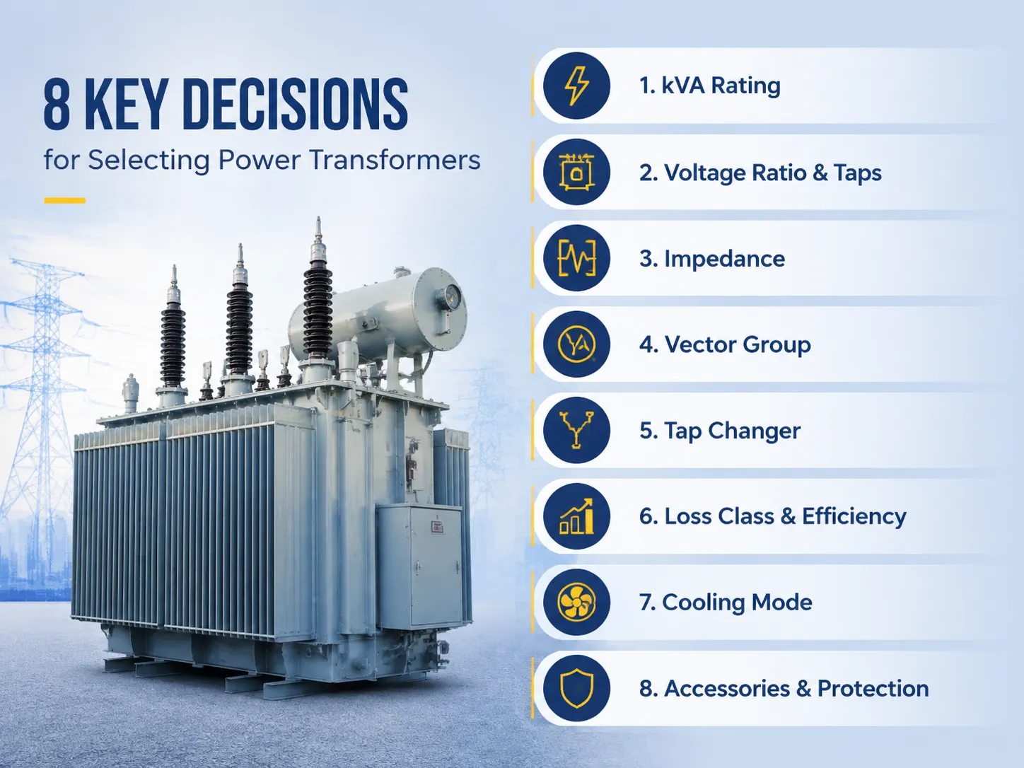
En bref, lors de la sélection d'un transformateur rempli d'huile, huit variables importantes entrent en jeu : (1) la taille de kVA doit tenir compte des pics maximaux plus une marge de 15 à 25 pour cent ; (2) les rapports de tension doivent être alignés avec ceux du fournisseur de services et de la ligne du planteur ; (3) l'impédance est fréquemment dans la fourchette de 4,5 à 8 pour cent en fonction de la classe et de la coordination du niveau de défaut ; (4) les groupes vectoriels doivent être synchronisés avec la mise à la terre du système et le degré de phase ; (5) la plage de prises est fixée à ±2 fois 2,5 pour cent hors circuit pour des réseaux stables ou ±8 fois 1,25 pour cent en circuit pour des réseaux faibles ; (6) la classe de pertes du transformateur est établie conformément à la norme GB 20052 ou à l'Ecodesign de l'UE en capitalisant sur les pertes ; (7) le refroidissement doit être choisi entre ONAN ou ONAF en fonction du facteur de charge ; et (8) l'équipement optionnel comprend un relais Buchholz, un PRD, un moniteur de température et un vibrothermomètre.
Table des matières
- Décision 1 : Dimensionnement de la puissance kVA
- Décision 2 : Rapport de tension et prises
- Décision 3 : Impédance
- Décision 4 : Groupe vectoriel
- Décision 5 : Choix du changeur de prises
- Décision 6 : Classe de pertes et efficacité
- Décision 7 : Mode de refroidissement
- Décision 8 : Accessoires et protection
- La méthode de sélection en six étapes
- Marques et conseils de prix
- Questions Fréquemment Posées
- Références
- Conclusion
Décision 1 : Dimensionnement de la puissance kVA
La décision qui guide toutes les autres est le dimensionnement, car chaque décision ultérieure se prend dans le contexte d'une enveloppe de puissance. La bonne méthode :
- Déterminer ou évaluer la demande de pointe. Utilisez les données de mesure sur un an (par exemple, étude de charge) ou, dans le cas d'un site nouveau, déterminez la charge connectée et appliquez un facteur de diversité (475 pour commercial et 0,5-0,8 pour la charge industrielle).
- Convertir en kVA. kVA = kW/facteur de puissance. Pour un facteur de puissance égal à 0,9, la demande de pointe de 1,8 MW se convertit en 2 000 kVA ; avec un facteur de puissance de 0,8 – en 2 250 kVA.
- Utilisez toujours le facteur de puissance réel ou prédit, pas 1,0.
- Introduisez la marge de croissance. Ajoutez 15-25% pour la croissance de la charge sur l'horizon de planification de 5-10 ans. Par exemple, 2 000 kVA devient 2 300-2 500 kVA.
- Arrondissez à la puissance nominale standard. Les incréments standard de kVA dans cette zone sont 1600/2000/2500 et 3150.
| kVA calculé (étude de charge) | Puissance nominale standard à commander | Application typique |
|---|---|---|
| Jusqu'à 400 kVA | 400 / 500 kVA | Petits commerces, villages |
| 400–800 kVA | 630 / 800 / 1 000 kVA | Usines, centres commerciaux |
| 800–1 300 kVA | 1 000 / 1 250 / 1 600 kVA | Industrie moyenne |
| 1 300–2 200 kVA | 2 000 / 2 500 kVA | Grandes usines, campus |
| Au-dessus de 2 200 kVA | 3 150 kVA et plus | Sous-stations, industrie lourde |
Choisissez la puissance nominale appropriée la plus proche qui dépasse la valeur calculée. Dans ce cas, la valeur déduite était de 2 500 kVA.
Deux erreurs courantes de dimensionnement sont coûteuses. Le surdimensionnement (par exemple, utiliser une unité de 3 150 kVA pour un besoin de 2 000 kVA) entraîne des dépenses inutiles avec des pertes à vide encourues tout au long de la vie de l'unité – la perte à vide d'une unité de 3 150 kVA (d'environ 4,4) est égale à $3100 par an à $0,08 par kWh. Le sous-dimensionnement provoque un fonctionnement en surcharge, entraîne un vieillissement des isolateurs et provoque des déclenchements lors des pics. La bonne taille est définie par l'étude de charge, pas par le chiffre rond du revendeur.
Décision 2 : Rapport de tension et prises
Le rapport de tension doit être égal aux deux extrémités du système : la tension du réseau et la tension dans le bus. Les paires les plus courantes sont données ci-dessous :
| Tension d'alimentation | Bus côté charge | Unité typique |
|---|---|---|
| 33 kV | 11 kV | Distribution 33/11 kV |
| 35 kV | 10,5 kV | Puissance 35/10,5 kV |
| 22 kV | 11 kV | Distribution 22/11 kV |
| 11 kV | 4 kV | Montée sur poteau ou socle 11/0,4 kV |
| 6 / 6.3 kV | 4 kV | 3/0.4 kV industriel |
La plage des prises est déterminée du côté haute tension et compense à la fois le changement de tension du réseau et la chute de tension du transformateur. Le cas où l'alimentation en tension est constante avec une précision de ±2.5% peut être réalisé à l'aide de prises hors circuit avec une position de ±2 × 2.5%. Dans les situations où l'alimentation est faible et/ou la charge change, un changeur de prises sous charge avec régulation de ±8 × 1.25% maintient le contrôle nécessaire. D'un point de vue économique, l'OLTC augmente le coût du transformateur de 15-30%, ce qui est raisonnable uniquement lorsqu'il y a effectivement des changements de tension.
Décision 3 : Impédance
Le facteur d'impédance (tension de court-circuit, UK%) détermine deux facteurs qui peuvent être en conflit l'un avec l'autre : les caractéristiques de régulation de tension et le courant de court-circuit. Une impédance plus faible est associée à une régulation plus forte, mais en même temps, elle entraîne un courant de court-circuit plus important. D'autre part, plus l'impédance est élevée, plus le courant de court-circuit sera faible, mais la chute de tension sera plus importante. La règle générale est de mettre en œuvre le transformateur qui est compatible avec les équipements de protection et de commutation déjà en service :
- Transformateurs de distribution (≤1 000 kVA) : 4 – 4.5% est la norme ;
- Transformateurs de taille moyenne (1,6 – 10 MVA) : 6% – 8% est la moyenne ; 7.5% est une spécification courante ;
- Transformateurs lourds (>10 MVA) : 8% – 14%, plus la puissance est élevée, plus l'impédance est élevée.
Une impédance inappropriée peut poser un risque de coordination. Si l'impédance choisie est trop faible, le transformateur fournira un courant de court-circuit qui dépassera la capacité du disjoncteur à se déclencher.
Décision 4 : Groupe vectoriel
La définition du groupe vectoriel englobe la configuration des enroulements et le décalage de phase du transformateur ainsi que sa configuration de mise à la terre et les exigences de fonctionnement en parallèle. Deux des groupes vectoriels les plus courants utilisés dans les transformateurs immergés dans l'huile sont :
- Dyn11 : Configuration delta du côté haute tension et configuration étoile du côté basse tension (avec le conducteur neutre sortant du transformateur). Cette désignation de groupe vectoriel est normalement utilisée pour les transformateurs de distribution (par exemple, 11/0.4 kV) fonctionnant dans des circuits monophasés ou triphasés.
- YNd11 : Configuration étoile du côté haute tension (avec le conducteur neutre sortant du transformateur) et configuration delta du côté basse tension. Cette désignation de groupe vectoriel est courante pour les transformateurs de puissance (par exemple, 35/10.5 kV) alimentant le côté mis à la terre par le neutre du transformateur.
L'importance du groupe vectoriel devient évidente lors du parallélisme de deux unités ou plus. Deux transformateurs connectés au même bus doivent avoir le même angle de décalage de phase ainsi que des impédances correspondantes égales à ±7.5%. Si les groupes vectoriels sont différents, des courants de circulation se mettent en place, provoquant une surchauffe des transformateurs, ce qui est un problème coûteux qui peut être évité en vérifiant la plaque signalétique.
Décision 5 : Choix du changeur de prises
Selon les experts, le changeur de prises est la seule pièce mobile du transformateur. La décision de sélectionner les prises est liée à la fiabilité.
| Taper | Plage typique | Fonctionnement | Impact sur le coût | Entretien |
|---|---|---|---|---|
| Hors circuit (DETC) | ±2 × 2,5% | Désénergisé uniquement | Référence | Aucun au-delà de l'inspection |
| Sous tension (OLTC), résistance immergée dans l'huile | ±8 × 1.25% ou ±6 × 1.67% | Sous charge | +15–30% | 50,000–100,000 opérations |
| OLTC, type vide | ±8 × 1,25% | Sous charge | +20–35% | 150,000–200,000 opérations |
Si l'alimentation est stable et que la charge est constante, les prises hors circuit peuvent être utilisées. Si une régulation sous charge est requise, l'alimentation doit varier de plus de ±2.5% en cas d'instabilité de la charge ou si le processus ne peut pas fonctionner en raison d'événements de sous-tension. La différence de prix ($6,000-12,000) d'une unité de 10 MVA semble insignifiante par rapport à la perte causée par un cas prolongé de sous-tension.
Décision 6 : Classe de pertes et efficacité
La plupart des coûts de durée de vie sont évalués dans la catégorie des pertes. Deux mesures de perte couramment utilisées sont la perte à vide (P0, continuant toute la journée) et la perte en charge (Pk, dépendant du carré du facteur de charge). Suivez les recommandations :
- Respectez les normes applicables : Vérifiez la norme GB 20052-2020 en Chine, le Règlement européen sur l'écoconception 548/2014 en Europe et le DOE américain 10 CFR Part 431 car ils ont une limite supérieure pour les pertes qui est très utile.
- Évaluez la différence : Chaque kW de P0 vaudrait tarif × 8,760 h × durée du projet. Chaque kW de Pk vaudrait tarif × 8,760 h × (facteur de charge moyen)² × durée du projet.
- Sélectionnez une classe à faible perte en cas de facteur de charge élevé : Avec des valeurs de P0 60-70% inférieures en utilisant un transformateur à noyau amorphe, un investissement peut être amorti en 6-12 ans et continuerait à générer des bénéfices.
Quelques statistiques sur une unité de 1,000 kVA : La technologie à faible perte a environ 1.1 kW de P0 inférieur à S11, ce qui représente environ $770/an à $0.08/kWh, $19,000 à payer pendant 25 ans contre $3,000-$6,000 à payer initialement.
| Facteur de charge | Perte à vide S11 (1,000 kVA) | Perte à vide amorphe | Économie annuelle @ $0.08/kWh |
|---|---|---|---|
| 3 (léger) | 7 kW | 6 kW | $770 |
| 6 (moyenne) | 7 kW | 6 kW | $770 |
| 9 (lourd / 24/7) | 7 kW | 6 kW | $770 |
La perte à vide reste similaire indépendamment du facteur de charge. Cela signifie que les économies restent constantes. Des heures de fonctionnement élevées garantissent que l'investissement dans le Premium impitoyable est rapidement récupéré.
Décision 7 : Mode de refroidissement
Lors de la mise en mode de refroidissement d'un transformateur, il déterminera la limite thermique et la surcharge autorisée. Ce qui suit indique les normes actuelles et leurs interprétations :
- ONAN : L'huile et l'air sont utilisés naturellement pour refroidir le transformateur. C'est le type de refroidissement le plus basique, le plus simple, silencieux et sans composants défaillants.
- ONAF : Des ventilateurs sont ajoutés en plus de l'huile pour le refroidissement. Cela augmente la puissance de 20 à 30 pour cent avec l'utilisation des ventilateurs, ce qui n'est approprié que pour des surcharges ou des charges intermittentes.
- OFAF/ODAF : La méthode de refroidissement forcé avec l'utilisation de ventilateurs pour les plus grands transformateurs – lorsque la chaleur ne peut pas être évacuée par le refroidissement par convection naturelle.
Si votre facteur de charge est inférieur à environ 0,8 et que vous avez seulement quelques pics – choisissez ONAN. Si vous prévoyez d'avoir souvent des surcharges à court terme – choisissez ONAN/ONAF : dans ce cas, votre transformateur de distribution de 1 000 kVA pourrait atteindre 1 250 kVA avec l'aide des ventilateurs. Assurez-vous que la carte de surcharge vérifie contre la norme IEC 60076-7.
| Mode de refroidissement | Évaluation de base | Marge de surcharge à court terme | Matériel |
|---|---|---|---|
| ONAN | 100% (plaque signalétique) | Typiquement 120–130% pour 1–2 h selon la norme IEC 60076-7 | Radiateurs uniquement |
| ONAN/ONAF | 100% avec ventilateurs éteints | +20–30% avec ventilateurs allumés | Radiateurs + ventilateurs |
| OFAF / ODAF | Évaluation du refroidissement forcé | Limité par le point chaud des enroulements | Pompes + ventilateurs |
Décision 8 : Accessoires et protection
La liste des accessoires est brève, elle est obligatoire lors de l'entretien et est souvent le point le plus crucial pour faire la différence entre l'incident et la catastrophe :
- Relais Buchholz (gaz) : Alarme de gaz lente et déclenchement rapide de l'huile pour les dispositifs de type conservateur de plus de ~1 MVA. Câblez-le et effectuez les tests.
- Dispositif de décharge de pression : Libère le réservoir de la pression interne ; dimensionnez-le en fonction du dispositif.
- Indicateurs de température d'huile et d'enroulement : Avec les alarmes et les déclenchements réglés selon le budget de montée de 65K.
- Jauge de niveau d'huile : Un niveau bas ouvre les enroulements ; vérifiez-le lors de la vérification trimestrielle.
- Déshydratant en gel de silice : Déshumidifie l'air qui entre dans le conservateur ; changez le gel de silice s'il est déjà rose.
- Contenant d'huile : Bund ou fosse dimensionnée pour accueillir le volume total d'huile, comme prescrit par la norme IEC 61936-1 et les réglementations locales.
Aucun de ces éléments ne coûte cher par rapport au dispositif et ensemble, ils transforment le transformateur immergé dans l'huile d'une menace d'incendie en un actif géré. Prévoyez 1–3% du prix unitaire pour l'ensemble de la protection.
La méthode de sélection en six étapes
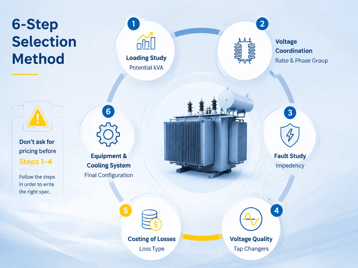
- Étude de charge : kW maximum, facteur de puissance, facteur de charge, plan de croissance → potentiel kVA.
- Coordination de tension : tension d'alimentation, tension de bus, mise à la terre, exigences d'interconnexion → rapport et groupe de phase.
- Étude de défaut : capacité de court-circuit, classifications des appareillages → impuissance.
- Décision sur la qualité de la tension : stabilité de l'alimentation et volatilité de la charge → type et gamme de changeurs de prises.
- Coût des pertes : tarif et facteur de charge → type de pertes (S11, S13, amorphe ou pertes de marque réglementée).
- Équipement et système de refroidissement : plan de surcharge, sécurité, stratégie de confinement → configuration finale.
Assurez-vous d'effectuer toutes ces étapes dans l'ordre et vous rédigerez la spécification. Le principal raccourci — demander des prix avant d'appliquer réellement les étapes 1-4 — est la raison de nombreux achats malheureux car cela donne tout le pouvoir à ceux qui répondent à la lettre en premier.
Marques et conseils de prix
| Marque | Origine | 1 000 kVA | 2,500 kVA | 10 MVA |
|---|---|---|---|---|
| Hitachi Energy | Japon/Global | $22,000–$34,000 | $38,000–$55,000 | $55,000–$82,000 |
| ABB | Suisse/Global | $20,000–$31,000 | $35,000–$52,000 | $52,000–$78,000 |
| Siemens Energy | Allemagne/Global | $21,000–$32,000 | $36,000–$53,000 | $50,000–$75,000 |
| Schneider Electric | France/Mondial | $19,000–$29,000 | $33,000–$48,000 | $48,000–$72,000 |
| Jiangsu Subian Electric Power | Chine | $14,000–$22,000 | $22,000–$34,000 | $28,000–$48,000 |
Les entreprises mondiales fournissent des solutions avec une ingénierie spécialisée, une expérience de tests sur le terrain et des capacités de service mondial, tandis que les producteurs offshore fournissent des produits conformes à la norme IEC à des tarifs très compétitifs. Après évaluation des risques, l'entretien de la dépense est fiable pour les éléments importants, tandis que l'alternative d'économie de coûts pour la production de masse est généralement réalisable.
Jiangsu Subian Electric Co. Ltd est un fabricant chinois de pompes à huile produisant des transformateurs de distribution et des transformateurs de puissance avec des tensions nominales de 35 à 110 kV conformément aux spécifications IEC 60076. Les rapports techniques de chaque unité, la conformité aux normes GB 20052 et la capacité de régulation de tension à vide font partie de l'expérience acquise par l'entreprise. Les détails des produits et les certificats sont à subian-electric.com.
Questions Fréquemment Posées
Comment puis-je calculer le kVA dont j'ai besoin ?
kVA = puissance kW maximale / facteur de puissance, plus une marge de croissance de 15 à 25 pour cent arrondie à une puissance standard. Par exemple, 1,8 MW à 90 pour cent de facteur de puissance équivaut à 2 000 kVA ; avec une marge de croissance de 25 pour cent, cela équivaut à 2 500 kVA. Chaque fois que possible, utilisez des données de pointe mesurées ; pour les nouveaux sites, additionnez la charge connectée et utilisez un facteur de diversité qui varie de 0,3 à 0,8, selon le type d'installation.
Quel rapport de tension devrais-je choisir ?
Assurez-vous que la tension de fonctionnement de votre bus du côté basse tension correspond aux tensions de l'utilitaire du côté haute tension, par exemple, 33/11 kV ou 35/10,5 kV ou 22/11 kV ou 11/0,4 kV. Obtenez une confirmation de la tension de fonctionnement par écrit de la part de la compagnie d'électricité avant de passer la commande ; notez que le passage du système de tension de 33 kV au système de tension de 35 kV n'est pas une tâche simple et nécessite une nouvelle conception.
Ai-je besoin d'un changeur de prises sous charge ?
Cela ne s'applique que si votre tension fluctue réellement. Si l'utilitaire maintient une stabilité dans une plage de ± 2,5 pour cent, et que votre charge est constante, des prises hors circuit à ± 2 par 2,5 pour cent sont adéquates. En revanche, si le réseau est faible, les fluctuations de charge sont plutôt importantes, ou si votre processus est sensible en termes de sous-tension, le coût supplémentaire d'un OLTC de 15 à 30 pour cent est compensé par une seule production évitée.
Combien coûte le bon transformateur ?
En termes généraux, en citant un fournisseur, les prix sont FOB $6 000 à $16 000 pour le transformateur de 500 kVA, $14 000 à $34 000 pour le transformateur de 1 000 kVA, $22 000 à $55 000 pour le transformateur de 2 500 kVA, et enfin $28 000 à $82 000 pour 10 MVA, selon le type, le fabricant et la taille du transformateur. Les frais de transport, d'installation et de travaux civils varient entre 15 et 40%, selon la localité.
Quelle est la différence entre Dyn11 et YNd11 ?
La combinaison standard pour les unités de distribution qui fournissent des charges monophasées et triphasées avec neutre est Dyn11. Pour les transformateurs de puissance 35/10,5 kV, la combinaison YNd11 s'applique car le côté haute tension est connecté à la terre via le neutre du transformateur. Le choix du type de connexion dépend de l'arrangement de mise à la terre et des exigences pour le fonctionnement en parallèle.
Références
- IEC 60076-1 : Transformateurs de puissance – Général — Évaluations, prises, tolérance d'impédance et règles d'élévation de température pour les décisions de sélection dans ce guide.
- IEC 60076-5 : Capacité à résister au court-circuit — Base de coordination de court-circuit pour la sélection d'impédance.
- IEC 60076-3 : Niveaux d'isolation et tests diélectriques — Niveaux d'impulsion par classe de tension référencés dans la spécification.
- Règlement européen sur l'écoconception 548/2014 (modifié 2019/1783) — Références de perte pour les acheteurs européens.
- Normes d'efficacité des transformateurs de distribution du DOE américain — Lignes de base d'efficacité minimale pour les acheteurs américains.
- IEEE C57.12.00 : Transformateurs de distribution et de puissance immergés dans un liquide — Exigences nord-américaines équivalentes pour la comparaison de sélection.
- Site officiel de Jiangsu Subian Electric Power — Gamme de transformateurs immergés dans l'huile, classes d'efficacité et documentation de certification.
Conclusion
Un transformateur immergé dans l'huile nécessite l'entrée de huit exigences différentes, au lieu d'une seule exigence en termes de coût. S'il est dimensionné, associé à d'autres composants et spécifié correctement, votre transformateur deviendra et restera un atout silencieux pendant environ 25 ans. Si ces étapes sont négligées et que la précipitation est montrée dans ce processus, le transformateur devient un mal de tête constant. Les points suivants sont les éléments clés que vous devez prendre en compte lors de la spécification de votre transformateur immergé dans l'huile :
- Commencez par une étude de charge appropriée et laissez une marge de 15-25% ; le calculateur de taille de kVA du transformateur n'est qu'une première étape pour déterminer le kVA requis du transformateur.
- Assurez-vous de connaître le rapport, l'impédance et les caractéristiques du groupe vectoriel de votre transformateur avant d'inviter des offres.
- Vous ne devez acheter un OLTC que pour maintenir un niveau de tension variable ; l'OLTC augmente le coût du transformateur de 15-30%.
- Le coût réel doit être calculé pour les pertes de puissance dans les transformateurs ; généralement, un transformateur à faible perte est rentable au fil des ans.