


승압 변압기와 강압 변압기는 전자기 유도를 통해 AC 전압을 변경하는 동일한 물리적 원리를 활용하지만, 전기 네트워크의 양쪽에 위치하며 전압과 전류 측면에서 수행하는 기능이 서로 반대입니다. 동일한 메커니즘으로 작동하더라도, 이는 품질 면에서 차이가 있음을 의미하지 않습니다. 오히려 이들 간의 전체적인 차이는 한 변압기가 다른 변압기보다 더 많은 회전을 가진 코일을 가지고 있다는 사실에 있으며, 이는 설치 장소에 따라 변압기가 전압과 전류에 미치는 영향을 결정하고 기계의 가격에도 엄청난 영향을 미칠 것입니다. 이 기사는 변압기 유형의 모든 특징을 설명하고 구매자에게 실용적인 조언을 제공합니다.
답변은 다음과 같습니다: 승압 변압기는 1차보다 2차에 더 많은 코일이 감겨져 설계되어, 입력보다 출력에서 더 높은 전압을 생성합니다. 이 방법을 사용하여 더 높은 전압으로 전력을 전송함으로써 저항 손실을 줄이는 동일한 원리가 적용됩니다. 강압 변압기는 2차에서 1차보다 회전수가 적기 때문에, 출력 전류의 비례적 증가와 함께 더 낮은 전압을 생성합니다. 두 유형의 변압기는 동일한 방정식 Vs/Vp = Ns/Np에 기반하지만, 전류는 반비례 관계입니다. 변압기는 반대로 설치되면 어느 유형으로든 작동할 수 있지만, 강압 변압기는 권선 구조, 절연 및 특정 전력 흐름 모드와 관련된 냉각 시스템 때문에 승압 변압기로 전환할 때 항상 정격 출력을 생성하지 않을 수 있습니다.
두 유형의 차이점
두 장치는 모두 정적 기계의 유형입니다. 각 장치는 자기 코어에 두 개 이상의 권선을 가지고 있습니다. 1차 권선은 교류 전류를 운반하고 자기 코어 내에서 변화하는 플럭스를 생성합니다. 이 플럭스는 2차 권선이라고 불리는 다른 권선에 유도 전압을 생성합니다. 두 권선은 2권선 변압기에서 서로 전기적으로 연결되어 있지 않습니다. 두 장치 모두 이동 부품이 없습니다.
승압 변압기를 강압 변압기와 구분하는 유일한 설계 특징은 회전비입니다. 2차 권선의 회전수가 1차 권선보다 많을 경우, 2차 권선에서 유도된 전압이 더 높아지고 변압기는 승압 변압기가 됩니다. 2차 권선의 회전수가 1차 권선보다 적으면 전압이 낮아지고 변압기는 강압 변압기가 됩니다. 변압기의 모든 다른 특징은 언급된 회전비가 실현되는 방식과 관련이 있습니다.
이것은 꽤 널리 퍼진 오해의 정확한 지점이라고 말하는 것이 중요합니다. 요점은 스텝업 변압기가 스텝다운 변압기보다 더 강력하지 않다는 것입니다. 스텝업 변압기의 정격이 500 kVA라는 사실은 동일한 전력을 가진 스텝다운 변압기보다 더 강력한 기계가 된다는 것을 의미하지 않습니다.
승압 변압기는 어떻게 작동하나요?
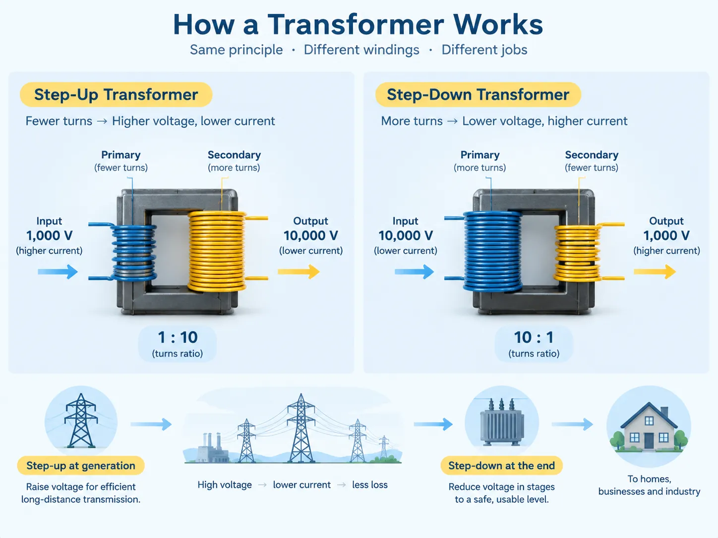
스텝업 변압기의 사용은 전기 공급이 더 적은 수의 권선에 공급되고, 사용은 더 많은 수의 권선에서 이루어진다는 것을 의미합니다. 만약 기본 권선의 회전수가 100이고, 보조 권선의 회전수가 1,000이라면, 회전비는 1:10이 되고 변압기의 보조 지점에서의 전압은 기본 지점에서의 전압보다 10배 더 높아야 하며, 손실 및 조정과 관련된 몇 가지 예외가 있습니다.
주요 요점은 전류에 미치는 영향입니다. 변압기는 전력을 생성하는 것이 아니라 단지 전력을 전달하기 때문에, 전압이 증가하면 전류는 감소합니다. 예를 들어, 스텝업 변압기가 1,000볼트의 공급에서 10,000볼트의 전압을 통과시키면, 전류는 기본 권선의 초기 전류의 1/10로 떨어집니다. 이 관계는 변압기의 단점이 아니라, 전압이 높을수록 전류가 작아진다는 일반적인 물리 법칙에 따라 변압기의 주요 목표입니다.
따라서 스텝업 변압기는 전력 생성 측면에서 모든 전력 시스템에서 발견될 수 있습니다. 발전기는 절연에 의해 제한된 전압, 즉 대형 발전기에서 11 kV에서 25 kV까지의 전압에서 전기를 생성합니다. 그 후, 스텝업 변압기는 이 전압을 필요한 전송 값으로 증가시키며, 이는 275 kV에서 400 kV 이상이 될 수 있습니다. 이러한 기계가 어떻게 구축되고 네트워크에서 어디에 위치하는지에 대한 기본 원리는 배전 변압기의 기본 구조와 역할, 에서 설명됩니다. 이들은 더 작은 규모에서 동일한 원리를 공유합니다.
스텝다운 변압기가 작동하는 방식
스텝다운 변압기에서는 권선의 순서가 반전되어, 공급이 더 많은 수의 회전수를 가진 권선에 적용되고, 부하가 더 적은 수의 회전수를 가진 권선에서 가져옵니다. 10:1 비율의 스텝다운 변압기의 예에서, 10,000 V로 공급되면 1,000 V를 공급하며, 출력 전류도 동일한 10배의 비율로 증가합니다.
스텝다운 변압기가 존재하는 이유 중 하나는 발전 지점에서 사용 지점까지 전송에 효율적인 전압 간에 큰 차이가 있기 때문입니다. 장거리 전송의 경우 275 kV의 전송 전압이 사용될 수 있지만, 실제로는 그러한 고전압에 건물, 장비 또는 기기를 연결할 수 없습니다. 전압은 실용적인 사용에 적합한 수준으로 점진적으로 감소해야 합니다. 이를 위해 전송에서 서브 전송으로, 그 다음에는 1차 배전으로, 마지막으로 설치에 적합한 수준으로 여러 단계로 줄일 수 있습니다. 공급이 설정되기 전에 여러 번의 스텝다운 변환이 수행되어야 할 수 있습니다.
스텝다운 변압기의 작동에 대한 특정 특징을 언급해야 합니다. 우선, 전압이 감소하면 저전압 권선에서의 전류가 고전압 권선보다 훨씬 높은 값을 가지며, 그렇기 때문에 저전압 권선은 고전압 권선보다 더 두껍게 만들어져야 합니다. 이것이 변압기의 저전압 권선을 쉽게 인식할 수 있는 이유입니다. 둘째, 출력에서 전압 안정성이 더 중요하게 느껴지며, 설치는 특정 전압 범위 내에서만 허용됩니다. 이름표 및 사양 매개변수의 전체 세트와 각 매개변수가 서비스에서의 동작에 미치는 영향은 변압기 사양 해석.
나란히 비교
| 매개변수 | 스텝업 변압기 | 스텝다운 변압기 |
|---|---|---|
| 권선 비율 | 2차 권선 > 1차 권선 | 2차 권선 < 1차 권선 |
| 전압 | 입력보다 높은 출력 | 입력보다 낮은 출력 |
| 전류 | 입력보다 낮은 출력, 반비례 | 입력보다 높은 출력, 반비례 |
| 전력 | 손실을 제외하고는 변하지 않음 | 손실을 제외하고는 변하지 않음 |
| 주요 기능 | 전압을 높여 전송 손실을 줄임 | 전압을 사용 가능한 수준으로 줄임 |
| 일반적인 위치 | 발전소 및 배전을 위해 전압을 높여야 하는 지점에서 | 변전소, 건물 공급 지점 및 사용 지점마다 |
| 일반적인 전압 쌍 | 11-25 kV에서 132-400 kV까지 | 132-400 kV에서 11-33 kV로, 그 다음 400 V 또는 230 V로 |
| 더 두꺼운 권선 | 2차(고전압), 그러나 절연이 우선 | 2차(저전압), 전류가 더 높기 때문에 |
| 절연 강조 | 두꺼운 — 고전압 권선이 설계를 주도하고 간격을 결정함 | 고전압 측에서는 보통, 저전압 측에서는 최소 |
| 동일 MVA에서의 일반적인 상대 비용 | 절연 및 간격 요구 사항 때문에 더 높음 | 동일한 겉보기 전력 정격에 대해 더 낮음 |
| 효율성 | 매우 높음, 일반적으로 대형 정격에서 98-99% | 매우 높음, 일반적으로 크기에 따라 97-99% |
| 원칙적으로 가역적 | 예, 설계 한계 내에서 역전원이 공급될 경우 | 예, 설계 한계 내에서 역전원이 공급될 경우 |
한 줄은 고객을 놀라게 하기 때문에 약간의 설명이 필요합니다. 두 종류의 변압기가 동일한 전력을 처리한다면, 왜 승압 변압기가 그에 상응하는 변압기보다 더 비쌀까요? 그 답은 절연 시스템에 있습니다. 고전압 2차측으로 설계된 변압기는 권선 절연, 부싱, 지면과의 간격 및 임펄스 내전압을 처리해야 합니다. 이러한 요구 사항은 전력보다는 전압에 따라 달라집니다. 따라서 50 MVA 11 kV/132 kV 승압 변압기는 일반적으로 크고 더 나은 절연을 갖추고 있으며 50 MVA 132 kV/11 kV 강압 변압기보다 더 비쌀 것입니다. 두 장치가 사양상 비슷해 보일 수 있지만 말입니다.
How They Differ Physically
The external appearance of a step-up and a step-down transformer with the same specifications can be confusing due to the similar construction. And yet, there are certain features the transformer has that help determine its type.
- Bushing height and size. Thanks to the high-voltage winding, the bushing design is different. With that in mind, it is easy to tell which side is used for high-voltage transmission. In a step-up transformer that would be the secondary winding, while in a step-down transformer, it would be the primary one.
- Winding conductor cross-section. If there is an opportunity to make a visual check, it is possible to say whether the winding belongs to a step-up transformer or a step-down transformer by the thickness of the conductors.
- Cooling arrangement. In case of the larger units of both speculations, there are radiators, fans or pumps to provide oil for cooling, but it is not a distinguishing feature for both types, as the cooling class is given in the rating plate.
- Taps used in the winding. The tap changer is usually installed on the high-voltage winding, as this construction allows fine tuning of the transformer for the same number of turns in the winding.
In all cases, the nameplate proves to be of great help in deciding which type of the transformer is available.
Where Each Is Used
The two types occupy opposite ends of a chain that every unit of electricity passes through.
| 단계 | 변압기 역할 | 일반적인 정격 |
|---|---|---|
| 발전 | Generator step-up transformer raises machine voltage to transmission level | 50-1,000 MVA |
| 전송 | Step-up and step-down at interconnection points between voltage levels | 100-1,000 MVA |
| 하전송 | Step-down from transmission to sub-transmission voltage | 20-200 MVA |
| 1차 분배 | Step-down from sub-transmission to distribution voltage | 5-50 MVA |
| 배급 변전소 | Step-down to utilisation voltage for an area or a large site | 0.5-5 MVA |
| Point of use | Step-down to the installation’s operating voltage, or local step-up for a specific machine | 0.025-2.5 MVA |
| Specialist local use | Step-up for a specific process or test requirement, such as electrostatic precipitators or test benches | Varies widely |
It can be inferred from the last two rows that both forms of transformations can occur in the same factory facility. A factory can receive electricity by the step-down transformer and then it may have a small step-up transformer to use it for a specific process such as electrostatic precipitators or dielectric test sets, or special equipment which requires higher voltage than what is supplied through the distribution. The direction of the transformation depends on the needs and not on the place where it is located; thus, the sizing problem has to be solved based on the requirements in terms of voltage and power.Getting that arithmetic right is a prerequisite for specifying anything correctly, and the method is set out in the approach to transformer sizing and load calculation.
유형 및 구성
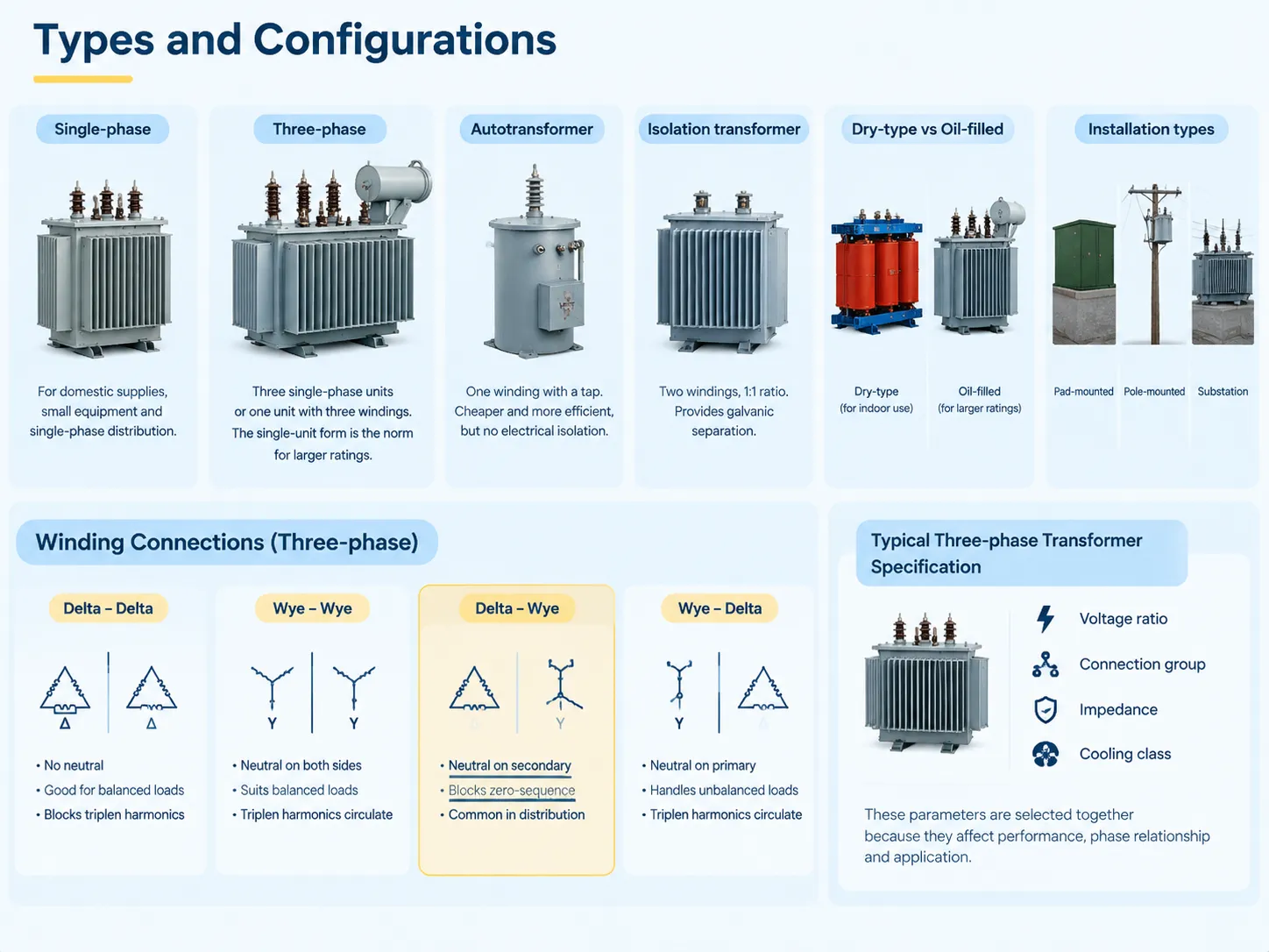
The construction family of the transformers does not tally with the direction of transformation, since both step-up and step-down transformers belong to the same family of construction.
- Single-phase. Made up of two windings on one core, widely used for home and small equipment supply and distribution, commonly used for smaller capacities.
- Three-phase. Consisting of either three single-phase transformers, or one three-phase transformer which has three windings on the same core. The second design favours the majority of transformer constructions due to its inherent capacity for powering transformers of very large rating and in providing installation with other parameters related to transformer operation.
- Autotransformer. A transformer with a single winding on tap that has electromagnetic coupling of circuits. It is the most cost-effective solution when compared to a two-winding transformer for similar purpose.
- Isolation transformer. A transformer with two windings and 1:1 turns ratio designed for specific needs of galvanic isolation.
- Dry and oil-filled types. Their distinction lies in the location where they are used: the dry type can work in closed spaces and the oil-filled ones are mostly employed for transformers that are big enough and have higher capacities, since oil cooling is more effective than air one.
- Pad-mounted and pole-mounted transformers, or transformers in substations. They are rather concerned with the installation methods than with the principle of transformers’ work.
For work done over three phases, the way the windings are connected — whether through delta or wye — significantly affects how phases of primary and secondary work together, along with whether a neutral is there and how unbalanced loads and triplen harmonics are handled by the transformer. An example would be a delta-wye connection that offers a neutral at the secondary and blocks the zero-sequence current from passing through it.The practical implications of each combination are significant enough to drive the specification, and a representative example of how a three-phase unit is presented for procurement is the 삼상 변압기 범위, where voltage ratio, connection group, impedance and cooling class appear together because they must be selected together.
Prices and Cost Drivers
Transformer pricing is conditioned by similar factors in the opposite direction, where direction of the installed unit does not matter as much as voltage class or voltage rating.
| Cost driver | Effect on price | 이유 |
|---|---|---|
| Power rating (kVA or MVA) | Dominant driver; price rises faster than rating | More core steel, more copper, more oil, larger tank |
| 전압 클래스 | Major driver, especially on the high-voltage side | Insulation, clearances and bushing costs scale steeply with voltage |
| Cooling class (ONAN, ONAF, OFAF) | 보통 | Radiators, fans and pumps add cost but raise usable rating |
| Impedance specification | 보통 | Low impedance costs more in material; affects fault level and regulation |
| Tap changer (off-circuit or on-load) | Significant for on-load | On-load tap changers are complex mechanisms with their own controls |
| 손실 사양 | Significant | Low-loss designs use more active material to reduce operating cost |
| Connection group and neutral arrangement | Minor to moderate | Affects winding configuration and any neutral bushing |
For the buyer, the key factors are that when comparing price offers from multiple suppliers, a product specification should be taken into account, since, after all, cheap price often translates into cheaper voltage class, small cooling margin or higher losses than in a good deal; and that the price of the product is only one part of the total cost, since losses are paid throughout the entire service life of the product. Reconciling capital cost against lifetime energy cost is the central exercise in transformer procurement, and the realistic price bands for each rating and class are set out in the cost structure for electrical transformers.
Can a Step-Down Be Used as a Step-Up?
In theory, it is possible. A transformer is a reversible device and turning the supply towards what is being called its secondary will mean that the voltage on what is being called primary will be higher than expected. On some occasions, this is done on purpose in case of emergency.
However, in reality the following four points define the reason why this is a bad idea unless made as part of a rational engineering choice. They are usually installed on the high-voltage winding which implies that reverse feeding of the transformer will situate them in unsuitable places for voltage adjustment. The insulation and distances were made with the assumption that the high voltage will appear on a certain winding, but back-feeding can expose this voltage to a wiring arrangement not convenient for it. The parameters for cooling and current ratings were set with a certain current distribution through the windings assumed, which will now turn when the power flow gets reversed. The protection and earthing system that would normally be designed for a particular direction of power flow will not be suitable for reversed flow either.
To summarize, reversal is theoretically possible to do, may be appropriate in certain situations, but is better clarified with the manufacturer rather than assumed. If one does require both directions at site, using a transformer properly selected for the job would be a much smarter approach than compromising by using whatever transformer one happens to have.
How to Tell Which You Have
Four tests in an order of reliability.
- Check the rating plate. It states the rated voltage of each winding as identified by terminal markings as well as the rated power, type of connection group, impedance, and the class of cooling. This is the most accurate test and can be carried out within seconds. If it is not possible to identify rating plate because of its illegibility or absence then other tests will become just approximations.
- The next test is to make a comparison of bushings and the clearance. The high-voltage side is identified by the side where bushings are larger and spacing and clearance to the earth are wider.
- Make a check of the size of the conductors whenever it is possible to see it. The heavier conductor belongs to the winding with the higher current and lower voltage.
- Trace the connection. Follow the supply line to find out which winding is the primary one and compare it with the rated voltage of the winding being investigated.
There are two remarks about field identification. If a transformer has a ratio of 1:1, for example, that is the isolation transformer, it does not step-up or step-down voltage and an attempt to identify the transformer by the direction will yield only a wrong result. Moreover, a transformer having many taps can be connected in such a way as to change its nominal ratio. Thus what is shown on the plate may not reflect the actual situation.
자주 묻는 질문
What is the difference between step-up transformers and step-down transformers?
The differentiation resides in the number of coils in winding. A step-up transformer has a greater number of coils in the secondary coil because of which the voltage of the output is greater than that of the input as well as the current is less proportionately. The purpose of the step-up transformer is to boost the voltage level to ensure the efficiency of power transmission. Meanwhile, a step-down transformer decreases the number of coils in its secondary coil leading to the decrease of voltage and increase of current in the proportion. The step-down transformer is used to lower the voltage to an appropriate level. Though both transformers operate at the same efficiency level, the following equation is true for both types of transformers Vs/Vp = Ns/Np.
What is the disadvantage of a step-up transformer?
There are three drawbacks that should be taken into account. To begin with, with the same power rating, costs tend to be higher than for step-down transformers as the high-voltage winding uses insulated parts and clearance materials that are connected with voltage parameters rather than power output. Next comes the risk that is connected with the potential failure of insulation systems due to the greater power of possible failures in the case of using high voltage equipment. Thirdly, when one uses a step-up transformer supplying a long cable, it is necessary to address voltage rise at the cable ends due to low voltage load conditions. Despite the fact that step-up transformers are quite reliable under normal conditions, all of the indicated factors affect the process of their specification and protection.
Can a step-down transformer be used as a step-up transformer?
In terms of functionality, the transformer can certainly operate in a reverse mode as there are situations where this is done in emergency situations. However, a device that has been intentionally built for use as a step-down transformer will usually not be able to achieve its full capacity when connected to the line in reverse mode because of numerous factors including but not limited to the design of the transformer in terms of winding construction, number of taps in use, and cooling arrangements. In reverse operation, the taps will usually remain on the primary (high voltage) side which may be regarded as inappropriate for operation. It is always advisable to check the reversibility option with the manufacturer and the devices that are made specifically for this purpose should be installed rather than recompleting the one that was not made for reverse operation.
How to tell if it’s a step-up or step-down transformer?
Examine the rating plate, which provides the rated voltage for each winding and is conclusive. In the absence of the rating plate, compare the bushings; the side with the bigger bushings, greater spacing and larger clearance from earth is said to be the high-voltage side, meaning that it is the side to which the transformer steps up and down from. In instances where the conductors are visible, noting the sizes of the conductors is the second clue; since the larger conductor is used for the winding with the higher voltage and lower current. Then follow the supply line to find out which of the windings is in fact the primary, as transformers with various taps may not always be installed in the configurations that results in the effective ratio being same as in the nameplate specifications.
Which transformer is used in a substation?
In both cases, the substation serves the reciprocal function. In the primary substation, transmission voltage is lowered to the level of distribution voltage. Therefore, all transformers in this type of substation are called step-down transformers. In a generation facility, the substation serves a different purpose since it is raising the voltage produced by the generator to the level of voltage transmission by using a step-up transformer. When it comes to interconnection substations, they might work in both modes, as they may contain both step-up and step-down units depending on the direction in which electricity flows most frequently and switching the flow if the flow does not change at the generation and demand points.
참고 문헌
- International Electrotechnical Commission — IEC 60076 Power Transformers
- IEEE — Transformer Connections, Voltage Regulation and Loading Guides
- ANSI — ANSI C57 Series Power Transformers, Regulators and Reactors
- NFPA — National Electrical Code, Article 450 Transformers and Transformer Vaults
- U.S. Department of Energy — Transformer Efficiency and Distribution System Losses
결론
Step-up and step-down transformers are different sides of the same coin. The only difference is the number of turns in each transformer. In step-up transformers the secondary winding has more turns than the primary winding; thus, the transformer raises voltage and lowers current. Electricity transmission at high voltage is far more effective than doing so at low voltage — which is why the step-up transformer was invented in the first place. The step-down transformer on the other hand has fewer turns on the secondary winding and lowers voltage while raising current. Basically, there is no such thing as a transformer that could be connected to the transmission line. Both transformers transfer the same amount of power except for losses involved, and they obey the same formula Vs/Vp=Np/Ns. They are built in the same manner — the only thing that differentiates them is their position in the electric power transmission system and that makes step-up and step-down units price different. The step-down unit can be used as a step-up transformer but its efficiency will be the lowest because it is designed to work only in one way.