


상업 프로젝트에 사용되는 배전 변압기와 대조적으로, 데이터 센터 변압기는 특별한 역할을 합니다: 이들은 지원하는 부하에 가까이 배치되어야 하며, 높은 효율로 지속적으로 작동하고, 사인파 부하와는 다른 형태의 부하를 처리해야 합니다. 따라서 점화 위험과 변압기의 세 가지 속성: 고조파 성능, 열 여유, 부분 방전을 고려할 때 오일 변압기를 사용하는 것은 불가능합니다.
요약하자면: 데이터 센터에 전력을 연결하기 위해서는 Class H (180 °C) 열 절연, K-13 (일반적으로 K-20) 이상의 K-팩터 등급, 6% 임피던스, UPS 입력을 위한 Dyn11 벡터 그룹, 정격 전압의 1.1배에서 10 pC 이하의 부분 방전 시험 값, 그리고 성능 측면에서 DOE 2016 또는 EU 에코디자인 Tier 2에 따라 적합한 주조 수지 건식 변압기를 선택하는 것이 적합합니다. 데이터 센터 변압기의 일반적인 전력 등급은 각각 10 kV 및 35 kV에서 500 kVA와 3,750 kVA 사이입니다.
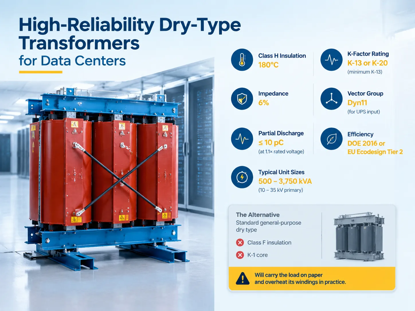
데이터 센터가 처음부터 건식 변압기를 사용하는 이유
주요 요인은 시스템의 화재 안전성입니다. 주조 수지 권선은 자가 소화할 수 있으며, 가연성 액체를 포함하지 않기 때문에 변압기를 제공할 부하에 가까운 건물에 배치할 수 있습니다. 따라서 오일 구덩이, 안전 벽 또는 좋은 내화 특성을 가진 특별한 구획이 필요하지 않습니다. 변압기는 IT 장비 근처에 배치되며, 공동 위치 또는 기업 데이터 센터에서 모든 평방 미터의 백색 공간이 소중하기 때문에 저전압 전선의 거리가 줄어듭니다.
다음으로 중요한 요인은 유지보수 요구 사항입니다. 오일 수준, 가스 릴레이 모니터링 또는 통풍구 건조가 필요하지 않습니다. 대신 부분 방전과 온도만 모니터링하면 되며, 이는 유체 화학 공정에 비해 간단합니다.
반면에, 건식 변압기는 열을 잘 견디지 못합니다. 오일은 이동하며 권선에서 열을 제거하는 데 도움을 주지만, 수지는 그렇게 하지 않습니다. 따라서 건식 변압기의 경우 절연 등급, 온도 상승 및 고조파가 훨씬 더 중요해지며, 정상 작동과 절연 손상 사이의 거리가 상당히 작아집니다.
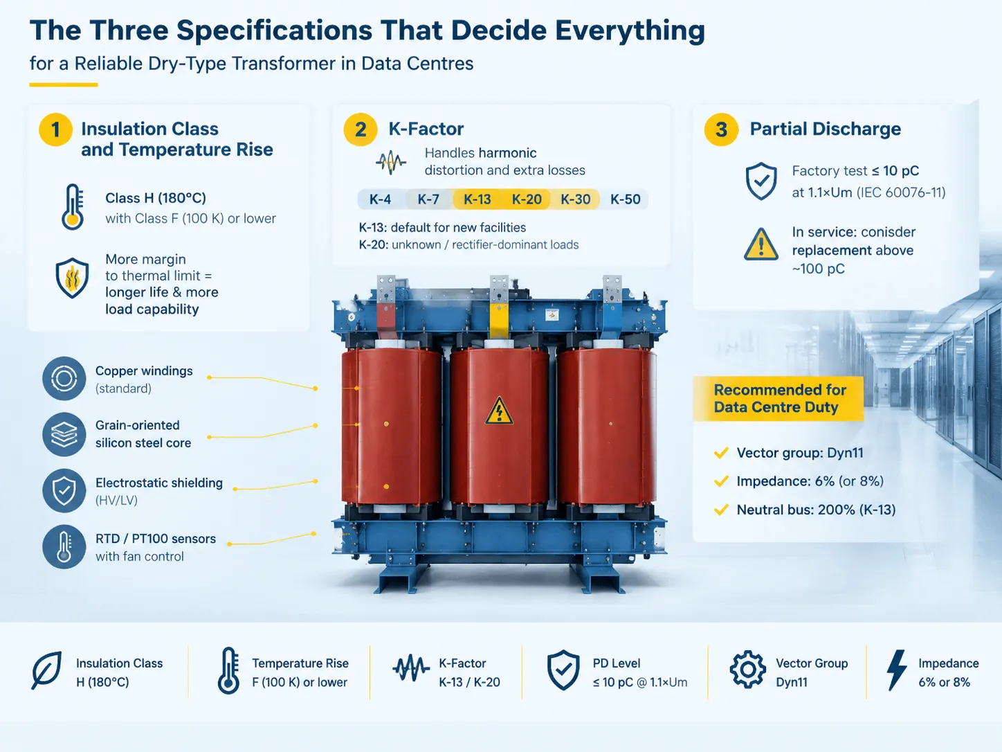
모든 것을 결정짓는 세 가지 사양
절연 등급 및 온도 상승
ANSI/IEEE C57.12.01에 따르면, 건식 변압기는 일반적으로 220도 섭씨 절연 시스템에서 40도 섭씨의 환경에서 80, 115 또는 150K의 온도 상승으로 평가됩니다. 따라서 동일한 장비에서 더 낮은 온도 상승은 열 제한성에 대한 더 큰 여유를 보장하여 절연 수명을 증가시키고 과부하에 대한 용량을 생성합니다.
IEC의 관점에서 절연 클래스는 클래스 F(155도) 및 클래스 H(180도)와 함께 정격 부하 중 관찰된 클래스 B 온도 상승(80도)에 해당합니다. 데이터 센터 사용을 위해서는 클래스 F의 클래스 B 온도 상승을 가진 클래스 H 절연을 요구하는 것이 표준 관행이며, 이는 변압기 작동 중 관찰된 온도보다 상당히 높은 온도로 특징지어진 절연을 의미하며, 작동 중 장비에서 발생하는 고조파 손실을 분산시킬 수 있는 공간을 남깁니다.
이는 입찰에서 가치를 낮추기 위해 가장 자주 수정되는 사양이며, 8년 후에 실패하는 제품입니다.
K-계수
K-계수 등급은 변압기가 열 제한을 위반하지 않고 분산할 수 있는 손실 수준을 결정합니다. 이는 IEEE C57.110 출판물에 따라 계산됩니다. UL 1561은 K-계수 가열 등급인 K-1, K-4, K-9, K-13, K-20, K-30, K-40 및 K-50 등급을 인정합니다.
선택은 실제 부하 특성에 따라 달라집니다:
| 부하 프로필 | 권장 K-계수 | 일반적인 고조파 내용 |
|---|---|---|
| 6-펄스 UPS 정류기가 있는 레거시 서버 | K-13 | 30–40% THD |
| 12-펄스 또는 IGBT 정류기가 있는 현대 서버 | K-7 | 15–25% THD |
| 능동 고조파 필터로 완전히 최적화됨 | K-4 | 10% THD 이하 |
| 혼합 부하, 고밀도, 미래 성장 불확실 | K-20 | 최대 여유 |
고조파 분석을 거치지 않은 신규 설치의 경우 K-13이 신중한 표준으로 간주되며, 부하 혼합이 불확실할 경우 K-20이 의무적인 수치입니다. K-20은 정류기 부하에 대해서도 가장 일반적으로 지정되는 값입니다.
K-등급 변압기는 단순히 더 무거운 코어 이상을 포함합니다. 이는 고조파 플럭스를 위한 낮은 플럭스 밀도를 사용하며, 더 큰 중성을 가지고 있습니다. K-13 변압기는 중성이 서로 상쇄되지 않고 중성에서 삼중 고조파가 합산되므로 200%의 상 등급으로 평가된 중성 버스를 가지고 있습니다.
K-등급 변압기가 없을 경우 결과는 명백합니다. 고조파 전류는 와전 손실을 증가시키고, 결과적으로 온도를 상승시키며 절연 열화를 가속화합니다. 고조파 플럭스는 또한 더 높은 피크 전압을 초래하므로 모든 고조파 값이 합산될 때 피크 값이 정격 정점의 1.25-1.5를 초과하면 부분 방전 발생의 매우 높은 확률로 이어집니다.
부분 방전
부분 방전은 고급 주조 수지 변압기와 경제적으로 제조된 변압기를 구별하는 정의입니다. IEC 60076-11에 따르면, PD 비율은 습기 있는 또는 야외 변압기에 적용되는 환경 카테고리 E2에 대해 정격 전압의 1.1배에서 최대 10 pC여야 합니다. 테스트 전압 1.1×Um에서 10 pC를 초과하는 PD 판독값을 보여주는 공장 보고서는 수용되지 않습니다.
작동에 관해서는 임계값이 변경됩니다. PD 값이 작동 전압에서 약 100 pC를 초과하면 절연이 이미 손상되어 교체 여부에 대한 질문이 제기됩니다. PD의 진행성과 문제가 외부에서 보이지 않는다는 사실은 구매 시 공장 테스트를 요청하고 추가 모니터링을 해야 함을 의미합니다.
데이터 센터의 전원 공급 장치에 대한 사양 언어는 다음과 같아야 합니다:
- 절연, H 등급 (180 °C), 온도 상승, F 등급 (100 K) 이하.
- K 계수, 최소 K-13, 정류기 또는 알 수 없는 부하의 경우 K-20, 고조파 부하에서 공장 수락으로 확인됨.
- 벡터 그룹 Dyn11을 UPS 입력 표준으로.
- 임피던스는 강화 전원 공급을 위해 6% 또는 단락 전류를 줄이기 위해 8%여야 합니다.
- 정전기 차폐는 HV와 LV 코일 사이에 배치되어 제로 순서 고조파 순환을 방지해야 합니다.
- PD는 IEC 60076-11 표준에 따라 공장에서 테스트되어야 하며, 확인이 필요합니다.
- 권선 재료는 구리, 코어 재료는 실리콘 강철, 온도 측정 장치는 RTD 또는 PT100과 냉각 시스템일 수 있습니다.
이러한 요구 사항 세트는 가장 저렴한 입찰이 아닌 장비가 다음 갱신 시점까지 여전히 서비스 중일 수 있는 장비를 생산합니다. 구매자가 사양을 작성하기 전에 고려해야 할 이유는 이 가이드에 설명되어 있습니다. 데이터 센터를 위한 드라이 타입 변압기를 선택할 때의 주요 지표와 함정, 입찰 문서가 발송되기 전에 읽어볼 가치가 있으며, 입찰이 돌아온 후가 아닙니다.
데이터 센터 작업에 적합한 드라이 타입 유닛의 유형
상업적으로 관련된 세 가지 유형의 구조가 있습니다.
- 주조 수지(에폭시) 드라이 타입. 주조 에폭시 수지에 밀폐된 권선. 이는 습기와 오염에 대한 저항력이 가장 크고, 자가 소화 능력과 2427 작업 주기의 열 사이클링을 견딜 수 있는 능력을 갖추고 있어 데이터 센터에 가장 적합한 선택입니다. 또한 높은 K 계수를 사용하여 사양을 지정하는 것이 가장 간단합니다.
- 진공 압력 침투(VPI). 진공 상태에서 바니시로 침투된 권선. 이는 주조 수지보다 저렴하고 기계적으로 저항력이 있지만 습기나 바다 근처의 조건에서 수분 침투에 더 취약합니다.
- 환기된 개방형 권선. 가장 저렴합니다. 이 결정은 데이터 센터 내부에 충분히 좋지 않은 경우가 드뭅니다.
It comes down usually to the choice of cast resin and the difference in quality of the resin, the winding design and the testing process.
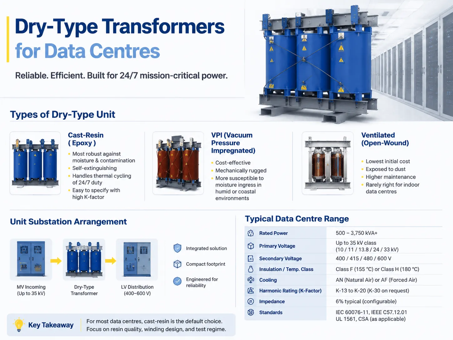
The Unit Substation Arrangement
Data centres are increasingly opting to purchase the complete power chain as one integrated, engineered product instead of acquiring the system as a series of components, such as the medium-voltage incoming section, cast resin transformer and low-voltage distribution system.
The pros of this approach include simplification of the interface and saving space. The cons are the issue of price comparison on single-source products and the fact that specifications of all parts involved become more important when welded into one component.
| 매개변수 | Typical data centre range |
|---|---|
| 정격 전력 | 500–3,750 kVA, larger for hyperscale |
| 1차 전압 | Up to 35 kV class — commonly 10, 11, 13.8, 24 or 33 kV |
| 2차 전압 | 400, 415, 480 or 600 V |
| Phases and frequency | Three-phase, 50 or 60 Hz |
| Insulation / temperature class | Class F (155 °C) or Class H (180 °C) |
| 냉각 | AN natural air, or AF forced air adding roughly 33–50% capacity |
| Harmonic rating | K-13 to K-20, K-30 on request |
| 임피던스 | 6% typical, configurable |
| 효율성 | DOE 2016 / EU Ecodesign / NRCan minimums |
| 표준 | IEC 60076-11, IEEE C57.12.01, UL 1561, CSA as applicable |
Before using forced-air cooling in design, it is essential to get a proper understanding of how this process works. Forced-air cooling stage helps increase kVA output, but it does this by drawing heat away from the device and not by enhancing the insulation. In a setup with N+1 cooling configuration, this is acceptable. However, in case of using a single fan setup, it is important to understand that an AF value will not be important as soon as one of the devices fails.
This means that the list with kVA output of 500, 630, 800, 1000, 1250, 1600, 2000, and 2500 should not be treated as just a menu that one can simply pick the required value from. The selection follows the load calculation, and a cast-resin platform covering the 6–10 kV distribution ratings — the SCB-series dry-type distribution transformer range is a typical example — will usually have the right frame available in the ladder, which is a consideration when the alternative is a custom build and a longer lead time.
Redundancy and Where the Transformers Sit
Selecting the data centre transformer is closely linked to the fault-tolerant topology that it is designed to support. The rating of the transformer is determined by the topology of the setup that is either Tier III or Tier IV based on N+1 or 2N arrangement of transformers.
- N+1- A spare transformer or an ability to lose 1 transformer from a group without tripping the load. This is the usual arrangement in Tier III facilities.
- 2N- Two fully rated but independent paths of supply. This means there can be 2 transformers feeding the same group of servers, which is common in Tier IV setups.
- Block redundancy/distributed redundancy- the power supply from transformers is shared by blocks, which leads to less kVA being installed.
When calculating the transformer size, it must consider the actual IT load instead of connected load. Remember that the physically selected size of the transformer affects the PUE, because even if the transformer is working below its capacity, it still results in significant losses that the facility will have to pay for. The possibility of using a number of small transformers instead of one large unit should be carefully evaluated. This is a design decision, not merely specification.
Where a facility is configured around a defined critical infrastructure topology, the arrangement of incoming supply, transformer and distribution is the part that decides whether a single failure is survivable, and the configuration options are set out in this look at power distribution solutions for data centre and critical infrastructure.
Efficiency Regulation Is Not Optional
The efficiency requirements are obligatory in major markets and forces equipment to be different in size as well.
- USA: Development of the 2016 Department of Energy (DOE) efficiency regulation, based on NEMA TP-1, refers to the distribution transformers. In this case, more core materials and conductors will be needed to manufacture equipment that satisfies current regulations.
- European Union: Regulation EC 548/2014 defines the minimum efficiency requirements for transformers with capacity higher than 1 kVA for 50 Hz circuits. Tier 1 requirements entered into force on July 1, 2015, while Tier 2 ones came into force on July 1, 2021. Tier 2 defines maximum no-load and load losses in watts for medium-sized dry transformers and establishes minimum efficiency for the rated capacity above 3,150 kVA.
- Canada: It sets the necessary minimum efficiency requirements for similar classes of transformers.
There can be two consequences of this requirement. Firstly, the compliance transformer should be larger in size and weight compared to the non-compliance transformer of the same rating. As a result, the construction space may be exposed to some changes. Secondly, efficiency requirement and K-factor pressure are directed in the same way in relation to manufacturing, which means that the compliance transformer is heavier in terms of conductive materials.
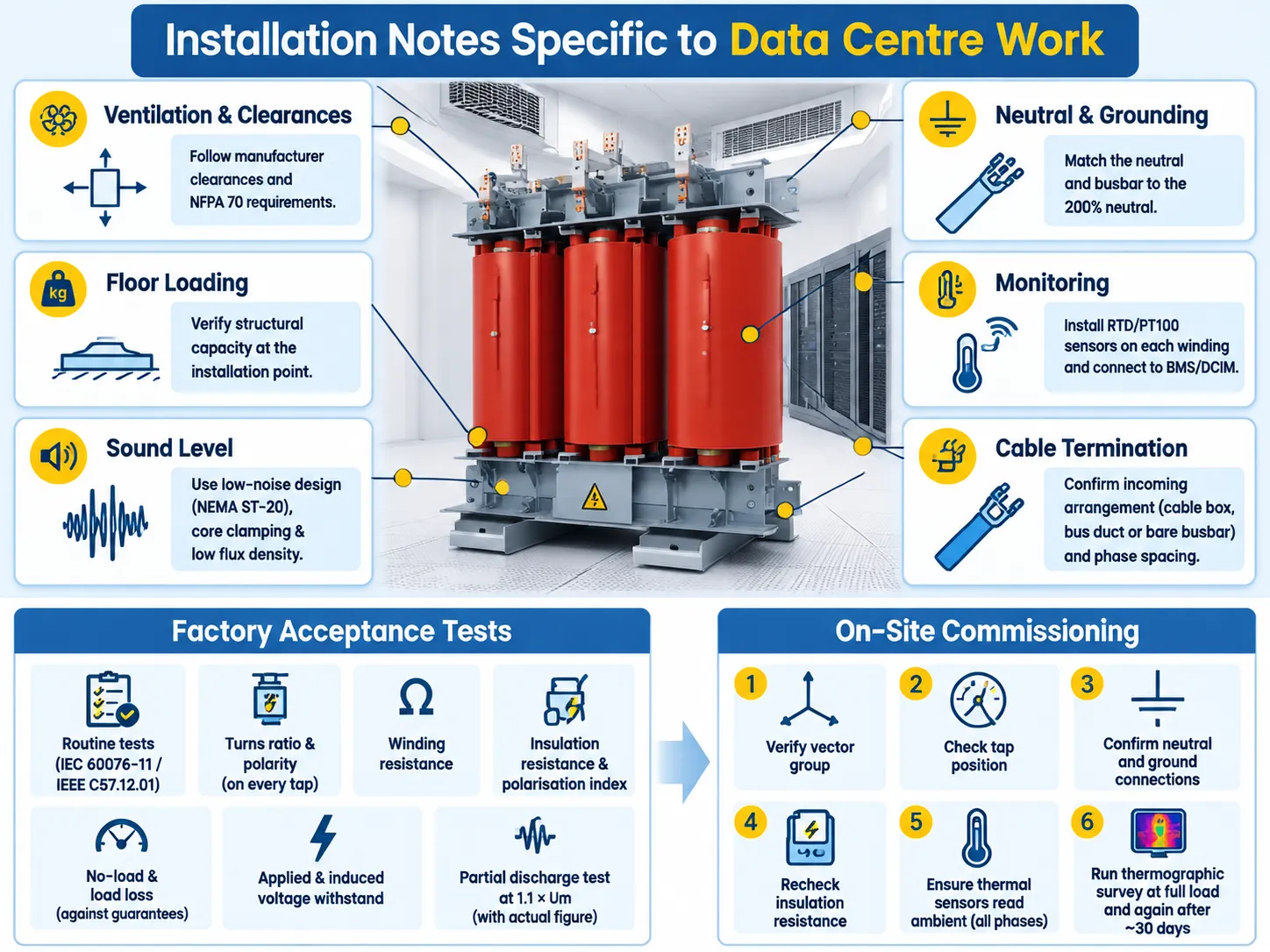
Installation Notes Specific to Data Centre Work
- Ventilation and clearances – be sure to check with the manufacturer for minimum clearances in all directions and above as well as against NFPA 70 installation requirements. Because a cast resin transformer dissipates the losses in the room, the air handling system must be sized to handle the losses.
- Floor loading – 2000 kVA of a cast resin transformer and enclosure means heavy equipment. It is important to confirm capacity of installation location, not just that of the entrance.
- Noise rating – quiet version per NEMA ST-20 is important if the transformer is located near occupied space. This is about core clamping and low flux density design.
- Grounding and neutral – A K-rated transformer with 200 % neutral means that the conductor and bus bar need to be sized accordingly for the downstream portion of the installation. This means that choosing the transformer and undersizing the neutral bar is bad practice.
- Monitoring – install RTD or PT100 sensors to all windings and connect them to the building management system or DCIM. This is the cheapest predictive maintenance you can get in dry-type transformers.
- Termination of cables – confirm whether this is cable box, bus duct or open busbar arrangement at the place of connection and check the phase distance at that point instead of a delivery site.
Acceptance Testing: What to Ask For
The factory acceptance test documentation must include at least the following elements: ordinary tests as required by IEC 60076-11/IEEE C57.12.01, turns ratio and polarity information for each tap, winding resistance value, insulation resistance value and polarization index value, values of no load and load losses from guaranteed numbers, results of the applied voltage withstand test and the induced voltage withstand test, result for the partial discharge test with 1.1 times Um indicated in the document as actual number.
If the transformer is K-rated, it is important to indicate some information on harmonics loading as per chosen K-factor value. Moreover, in cast resin transformers that operate in data centers, some checks must be conducted to ensure that there are no voids, cracks, or incomplete resin fill in the winding encapsulation.
At the installation site, before energizing the transformer and starting operation: confirm the vector group, tap position, neutral, and ground connection, insulation resistance as well as reading temperature in all the three phases. In addition, it is recommended to conduct a thermographic test at full load and to repeat it in a month afterward to check the ongoing temperature reading of both phases.
A structured commissioning sequence is worth following rather than improvising, and the routine tests that a dry-type unit should go through on arrival are set out in this seven-step routine test programme for dry-type transformers. Skipping the tests that are awkward to repeat after energisation is how a defective unit reaches full load before anyone knows.
Brands and How the Range Maps
The market for dry-type data center facilities can be divided into two groups: first is the construction of the entire power train and integration of the transformer into the overall design by global electrical companies, and second is the manufacturing of the transformer on specialized manufacturers’ facilities according to their specifications.
In the case of the specialized option, the key aspect would be whether the supplier has its whole production area for this purpose. Suppliers who can do cast resin dry-type projects from 6-10 kV to 35 kV with pre-tested DC solution would be working with the entire project from the same manufacturing premises instead of sourcing from different producers every time. This holds more value with phased projects than with one-time orders since the next batches of transformers produced have to work together. Subian fits this model as it is a Chinese company with dry-type and oil-immersed transformers fulfilling electrical, high-voltage and amorphous alloy transformers for international projects.
Speaking about the competitive analysis, SCB13 and its equivalents in cast resin technology is the platform on which all data center buyers compare the offers of local markets since the parameters used for each type are very similar even though the certification, methods of production may be different. That comparison is worked through in this note on how SCB13 dry-type transformers compare with international cast-resin designs, including where the differences are real and where they are documentation.
Normal price positioning works in a usual way: global brands at the top, specialist producers significantly below and the gap is becoming wider with the increase of kVA rating and the amount of customisation involved. What a buyer should not do is to compare a fully specified K-13 Class H unit with a K-1 Class F catalogue cost and thus surmise that that the cheaper product is indeed a bargain.
자주 묻는 질문
Why do data centres use dry-type instead of oil-filled transformers?
Fire safety and site. Cast-resin winding does not burn and has no combustible liquids, so this equipment can be installed indoors and near the load without an oil containment facility. Maintenance is easier since there is no oil testing or gas relay or breather. This implies lower temperature tolerance that makes insulation type, temperature rise and K-factor more important for dry-type data centres than for oil-filled distribution devices.
What K-factor do I need for a data centre transformer?
K-13 is the conservative option for a facility with no harmonic study and is appropriate for legacy servers using 6-pulse UPS rectifiers with THD of 30–40%. K-20 is the correct option for loads dominated by rectifiers or loads that may grow in the future. K-7 is appropriate for new installations using 12-pulse or IGBT rectifiers with THD of 15–25%, while K-4s are used only where active harmonic filters have brought down the THD to 10% or below. Always round up to the next standard rating.
How do I size a transformer for a data centre?
Consider the actual load of the IT equipment, as well as that of the UPS design. Apply redundancy through either an N+1 or a 2N system. Air caching solutions are required only for those areas where it is redundant. An excessively loaded device will have high no-load losses, thus smaller transformers with high efficiency in partial load operation can be better than one larger device in terms of capital expenditure and efficiency measures (PUE).
What partial discharge level is acceptable?
According to the stipulations of IEC 60076-11, at Environmental Category E2, the allowed PD level is not above 10 pC at 1.1 of the rated voltage. Any factory certificate indicating a higher value must be invalidated. Under operating conditions, values above approximately 100 pC at the nominal operating voltage means the insulation condition must be considered unsatisfactory and that the insulation will have to undergo further evaluation and likely replacement.
참고 문헌
- UL Solutions — UL 1561 for dry-type general purpose and power transformers, including recognised K-factor ratings
- Eaton — dry-type transformer application guidance, K-factor selection and harmonic loss explanation
- Schneider Electric — dry-type transformer specification data, temperature rise classes and efficiency compliance
- US Energy Information Administration — data centre electricity consumption and load growth analysis
- US Department of Energy — transformer efficiency standards and distribution transformer energy conservation rulemaking
- Uptime Institute — data centre tier classification, redundancy topologies and availability research
- ASHRAE — thermal guidelines and technical resources for data processing environments
- International Electrotechnical Commission — IEC 60076-11 for dry-type power transformers and IEC 60076-1 general requirements
결론
A dry-type transformer chosen for a data center has three key elements: the insulation category that exceeds significantly the temperature range of the transformer; the K factor that classifies the level of harmonic distortion for the operating load; and partial discharge testing. Properly adjusted insulation with a combination of thermal monitoring, energy efficiency, and extensive factory testing should ensure that the dry transformer will work for twenty years without failures. Any problems that might arise will become apparent only after eight years as a winding fault and by this time all savings provided by the contract will have been spent already.