


간단히 말해, 대부분의 충전소는 하나의 배전 변압기를 필요로 하며, 이는 중저전압 변압기로 분류될 수 있고, 충전기의 실제 동시 부하에 따라 설계됩니다 - 이름판 정격이 아니라, 하루 종일 몇 시간 동안의 고조파가 많은 공급 운영 및 현장에 특정한 공급 조건을 기준으로 합니다. 이는 일반적으로 개방 주차장에 설치된 패드 장착 변압기, 인공 구조물이나 지하 주차장에 설치된 주조 수지형 변압기, 대형 충전소/버스 차고에 설치된 조립식 변전소와 함께 공급을 유지하지만 일반적으로 미터기나 보호 계전기를 주문할 때까지 주목받지 않는 추가 전류 변압기 세트를 의미합니다.
이 가이드는 개발자, EPC 계약자 및 전기 컨설턴트를 위한 것으로, EV 충전소용 변압기를 사양에 포함시키는 책임이 있습니다. 변압기 유형 및 정격, 고조파에 대한 정보가 포함되어 있으며, 크기 조정의 예를 보여주고, 전류 변압기에 대해 논의하며, 공급업체를 위한 체크리스트를 제공합니다. 만약 당신이 여전히 그리드 계획 단계에 있다면, 우리의 동반 기사에서는 DOE 연구가 변압기 및 피더 업그레이드에 대해 무엇을 말하는지 가장 큰 2025 EV 충전 시장 보고서가 변압기 수요에 대해 무엇을 밝히는지.
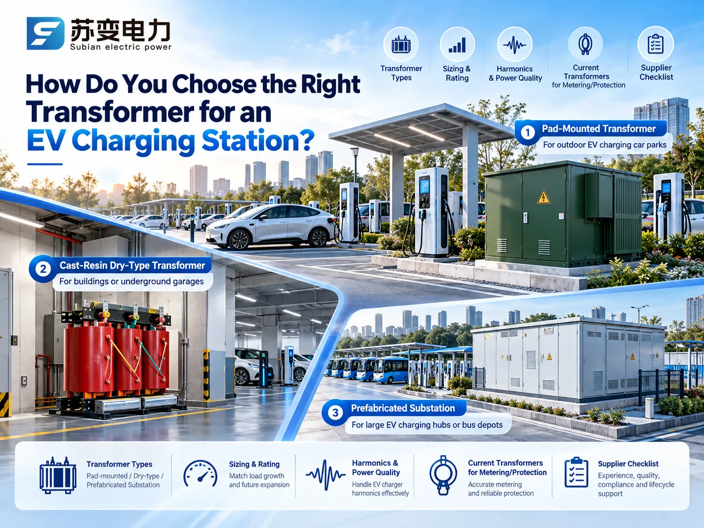
그리드와 EV 충전기 사이에 위치한 변압기는 무엇인가요?
주요 인수는 유틸리티 전압 공급을 10에서 35 kV로 줄여 충전기 전압으로 변환하는 변압기를 의미합니다. IEC 국가에서는 대부분의 경우 변압기 전압이 50 Hz에서 400/230 V이며, 대부분의 DC 또는 AC 충전기가 이를 직접 수용할 수 있습니다. 북미에서는 때때로 매우 낮은 전압 변압기가 480 V를 208Y/120 V로 변환하여 Level 2 충전기에 사용됩니다. 따라서 이 가이드의 나머지 부분은 현장 변압기에 초점을 맞추고 있으며, 이는 현장 에너지화의 성패를 좌우하는 고가의 긴 리드 아이템입니다.
충전 사이트에 맞는 변압기 유형
EV 충전소 변압기의 물리적 형태는 설치 위치, 사이트의 전력 소비량 및 접근이 필요한 사람에 따라 결정됩니다. 아래 표는 일반적인 시작점을 제공합니다. 사이트.
| 일반적인 수요 | 일반적인 변압기 형태 | 몇 개의 AC 포인트가 있는 농촌 전면 또는 소형 주차장 | 이유 |
|---|---|---|---|
| 150 kVA 미만 | 기둥 장착형 또는 소형 패드 장착 오일 유닛 | 이미 공중선이 있는 경우 가장 낮은 비용 | 슈퍼마켓, 호텔 또는 사무실 주차장에 혼합된 AC 및 DC |
| 250에서 1,000 kVA | 삼상 패드 장착 변압기 | 컴팩트하고 변조 방지 기능이 있으며, 충전기 옆의 콘크리트 패드에 설치됩니다. | 지하 주차장, 다층 주차장 또는 건물 지하실 |
| 250에서 2,500 kVA | 인클로저에 있는 주조 수지 건식 변압기 | 오일이 없고, 자가 소화성 절연체로 실내 화재 승인도 더 용이합니다. | 고속도로 급속 충전 허브 |
| 1에서 5 MVA | MV 스위치기어, 하나 또는 두 개의 변압기 및 LV 보드가 있는 조립식 변전소 | 테스트된 하나의 유닛으로 제공되어 현장 작업을 단축합니다. | 테스트된 단위로 제공되어 현장 작업을 단축합니다. |
| 버스 또는 트럭 차고, 종종 태양광 및 저장 장치와 함께 | 2에서 10 MVA 이상 | 여러 변압기가 조립식 변전소에 있으며, 때때로 33 kV 연결이 있습니다. | 중복성과 단계적으로 충전기 용량을 추가할 수 있는 공간 |
개방형 주차장을 위한 패드 장착 변압기
패드 장착 변압기는 변압기 장비, 중전압 연결 및 저전압 연결을 잠금 장치가 있는 인클로저에 포함합니다. 이 장치는 주차장 가장자리에, 충전기 근처에 설치할 수 있어 필요한 저전압 케이블의 양을 줄입니다. 120kW의 전력을 가진 DC 충전기는 400V에서 약 186A를 사용하므로 변압기와 충전소 사이의 매 미터의 케이블이 구리 비용을 증가시킵니다. Subian은 각 프로젝트의 네트워크 전압 및 표준에 맞게 구성된 삼상 패드 장착형 변압기를 제조합니다. 프로젝트 네트워크 전압, 벡터 그룹 및 표준에 맞게 구성됩니다.
차고 및 건물을 위한 건식 변압기
소방관과 보험 회사는 폐쇄된 주차장에서 오일 기반 장치에 대해 조심스럽습니다. 주물 수지로 만들어진 건식 변압기는 오일 저수조, 화재 안전 벽 및 오일 기반 장치에 필요한 것으로 보이는 충분한 검사 프로토콜을 우회하며, 약간 더 비싼 가격과 설계된 깨끗하고 환기된 공간의 요구 사항으로 거래됩니다. Subian의 문의하기 전에 검토할 수 있습니다. 모든 공급업체로부터 구매하는 올바른 방법은 사양을 고정하고 시험 증거를 요구하며 문서화된 수치로 비교하는 것입니다. 포함됩니다. 6에서 10 kV SCB 시리즈 에폭시 수지 주조 장치 일반적으로 건물 변전소에서 사용됩니다. 더 넓은 비교를 위해, 우리의 가이드를 참조하십시오. 건식 변압기 대 오일 침지 변압기.
허브 및 차고를 위한 조립식 변전소
사이트에 자체 MV 스위치기어와 최소 두 개의 변압기가 필요한 경우, 공장에서 제작된 변전소가 일반적으로 가장 빠른 옵션입니다. 링 메인 유닛, 변압기 및 LV 보드는 미리 배선되고 유형 테스트를 거쳐, 기초를 세우고 케이블을 끌고 현장에서 시운전하는 작업만 남습니다. Subian의 YB 시리즈 조립식 변전소 가장 큰 ZGS 시리즈 복합 변전소 이 역할을 수행하며, 우리의 컴팩트 변전소 가이드 하나를 지정하는 방법을 설명합니다. 우리의 2025 EV 충전 시장 보고서 평균 공공 충전기 전력이 계속 상승하고 있으므로 두 번째 변압기를 위한 공간을 레이아웃에 남겨두는 것이 유리합니다.
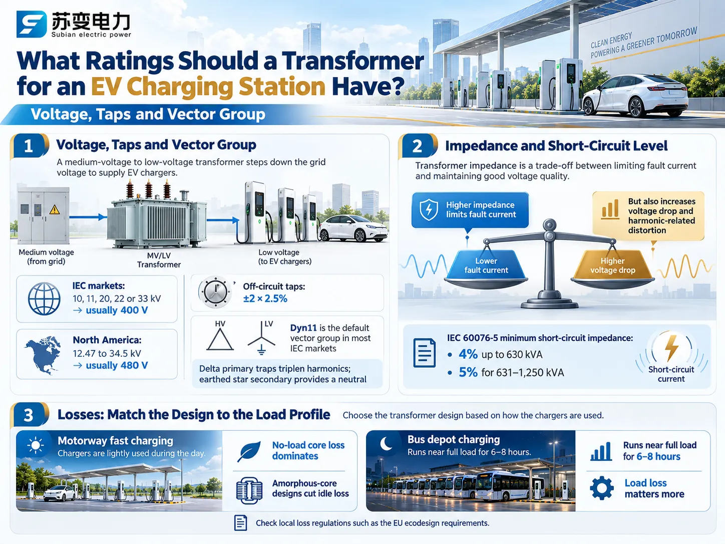
EV 충전소를 위한 변압기의 정격은 무엇이어야 합니까?
전압, 탭 및 벡터 그룹
1차 공급 전압의 경우, 연결된 지역 전력망의 전압 수준과 일치할 것으로 예상되며, 이는 IEC 규격에 따라 10~33 kV 또는 북미에서 12.4~34.5 kV임을 의미합니다. 2차 전압은 충전기 입력과 일치해야 하며, 일반적으로 IEC 규격의 경우 400 V, 북미의 경우 480 V의 전압 정격을 가집니다. 비부하 탭 체인저는 잘못된 1차 공급 전압 문제를 처리할 수 있지만, 일부 충전기는 입력 전압이 예상보다 낮을 때 성능 저하를 경험하므로 충전기 사양을 확인해야 합니다.
DC 고속 충전 응용 프로그램의 경우, Dyn11은 전체 IEC 표준 국가에서 일반적으로 사용되는 벡터 그룹입니다. 우리의 기사에서는 델타-와이 변압기가 작동하는 방식 기본 사항을 다룹니다.
임피던스 및 단락 수준
임피던스는 타협입니다. 높은 값은 저전압 스위치기어를 통해 흐르는 고장 전류를 줄이고 충전기의 자가 보호를 한계 내에서 유지하지만, 반면에 전압 강하를 증가시키고 더 큰 고조파 변압기 전압 왜곡을 초래합니다. IEC 60076-5에 따르면, 정격이 630 미만인 변압기의 최소 단락 임피던스는 4%이며, 631에서 1250 kVA 사이의 정격을 가진 변압기는 5%입니다. 이는 대부분의 변압기 제조업체에 해당합니다.
손실: 설계를 부하 프로필에 맞추기
고속 충전기는 고속도로에서 하루의 대부분 동안 유휴 상태일 수 있으므로, 하루 종일 흐르는 무부하 코어 손실이 에너지 비용을 지배합니다. Subian의 10 kV SCBH 시리즈 비정질 합금 건식 변압기, 는 이러한 유휴 손실을 급격히 줄입니다. 버스 차고는 반대입니다: 변압기는 매일 밤 6~8시간 동안 거의 전체 부하로 작동하므로 부하 손실이 더 중요합니다. 공급업체에게 귀하의 사이트가 따르는 패턴을 알려주고, 배급 변압기에 대한 EU 에코디자인 요구 사항과 같은 지역 손실 규정을 확인하십시오.
고조파 및 K-팩터: 대부분의 사양에서 간과되는 측면
모든 EV 충전기는 AC 전류를 DC로 변환하는 역할을 하여 비선형 유형의 부하로 작동합니다. 간단한 6펄스 다이오드 정류기는 5, 7, 11 및 13의 고조파를 포함하는 AC 전류를 생성하는 역할을 합니다. 대부분의 현대 고출력 충전기는 능동 전면 또는 비엔나 정류기를 사용합니다. 비엔나 정류기의 효과적인 능력을 입증하기 위해, IEEE Access 기사는 입력 전류 왜곡이 3.3% 미만일 수 있으며 IEEE 519에서 언급된 일반적인 5% 요구 사항보다 낮게 유지될 수 있다고 지적했습니다.
고조파 전류의 증가는 와전류와 누설 손실의 증가로 이어지며, 이는 변압기가 예상보다 더 따뜻한 조건에서 작동하게 됨을 의미합니다. IEEE C57.110은 특정 고조파 스펙트럼에 따라 감량을 측정하기 위한 알고리즘을 제공합니다. 미국에서는 K-팩터에 따라 K형 마킹이 있는 건식 변압기를 찾을 수 있습니다 (UL 1561). 일부 제조업체는 Level 1 및 Level 2 충전기에 K-9 유형 변압기를, EV 부하 범위가 상대적으로 작은 경우에는 K-4를 권장합니다. K-팩터 등급 관행이 적용되는 경우는 없으므로, 제조업체에 예상되는 고조파 전류 스펙트럼을 제공하는 것이 더 현명할 것입니다.
| 충전기 전단 | 지배적인 고조파 차수 | 전형적인 전류 THD | 변압기에 대한 의미 |
|---|---|---|---|
| 6-펄스 다이오드 정류기 | 5번째, 7번째, 11번째, 13번째 | 높음; 일반적으로 완화 없이 IEEE 519 및 IEC 한계를 초과함 | IEEE C57.110에 따라 감량, K-등급 장치 지정 또는 필터링 추가 |
| 12-펄스 정류기 | 11번째, 13번째, 23번째, 25번째 | 6-펄스보다 훨씬 낮으며, 5번째와 7번째는 대부분 상쇄됨 | 중간 정도의 추가 손실; 일반적으로 적당한 여유로 커버됨 |
| 능동 전단 또는 비엔나 정류기 | 저수준, 높은 차수 | 일반적으로 정격 부하에서 5% 미만 | 표준 설계는 일반적으로 적합하며; 충전기 데이터로 확인 |
문제를 최소화하기 위해 구현할 수 있는 두 가지 기술은 위상 이동과 전체 설치 평가입니다. 위상 이동은 두 개의 변압기 또는 30도 위상 차이를 가진 2차 권선 사이에 충전기를 분산시키는 것으로, 이는 상류 수준에서 5번째 및 7번째 고조파의 상쇄에 도움이 됩니다. 두 번째 기술은 전체 설치에 대한 평가를 수행하는 것입니다. IEC 61000-3-12는 고조파 기준을 정의하고 각 상에 대해 16 A를 초과하고 75 A까지의 장비 작업 한계를 설정합니다.
EV 충전소를 위한 변압기 크기 조정 방법
우리의 DOE 보고서 가이드를 참조하십시오. 순수 DC 고속 충전 허브를 통해 작동하며, 시장 보고서 기사 버스 차고의 크기를 조정합니다. 많은 실제 프로젝트는 혼합되어 있으므로, 여기에는 AC 및 DC 충전과 기존 건물 부하가 모두 포함된 소매 사이트가 있습니다.
가정: 120kW의 DC 충전기 4대는 부하 관리로 인해 75%의 일치 계수를 가지며, 효율성은 95%이고 역률은 0.98입니다. 22kW의 AC 충전기 12대는 차량이 몇 시간 동안 주차되어 있기 때문에 50%의 다양성 계수를 고려했습니다; 기존 조명, 냉장 및 작업장 부하의 전력 값은 60kVA; 충전기 및 고조파 열을 위한 20%의 여유를 추가합니다.
| 부하 | 계산 | 결과 |
|---|---|---|
| DC 충전기 | 4 × 120 kW × 0.75 ÷ 0.95 ÷ 0.98 | 약 387 kVA |
| AC 충전기 | 12 × 22 kW × 0.50 ÷ 0.99 | 약 133 kVA |
| 기존 건물 부하 | 측정된 대로 | 60 kVA |
| 총 일치 수요 | 387 + 133 + 60 | 약 580 kVA |
| 20% 여유 포함 | 580 × 1.2 | About 696 kVA |
| Next standard size | IEC practice / North American pad-mount | 800 kVA / 750 kVA |
The requirement for virtually the same power capacity without load management requires approximately 842 kVA at the outset and 1,011 kVA at the end, which translates into approximately 1,250 kVA according to IEC specifications. Load management is crucial as it indicates two types of transformers to be ordered and hence, should be specified ahead of the transformer order placement. For the steps between ratings, see our guide to standard transformer sizes, and for the basics, what a kVA rating means.
In addition to the above specification, the depot requires one more consideration. While standard distribution transformers can be overloaded to a certain degree due to the fact that residential loads cool down overnight, a depot that charges its buses only overnight cannot benefit from such cooling periods. It is important to follow loading instructions for oil-filled transformers given in IEC 60076-7 and for dry transformers in IEC 60076-12 since it will help to determine the precise charging patterns.
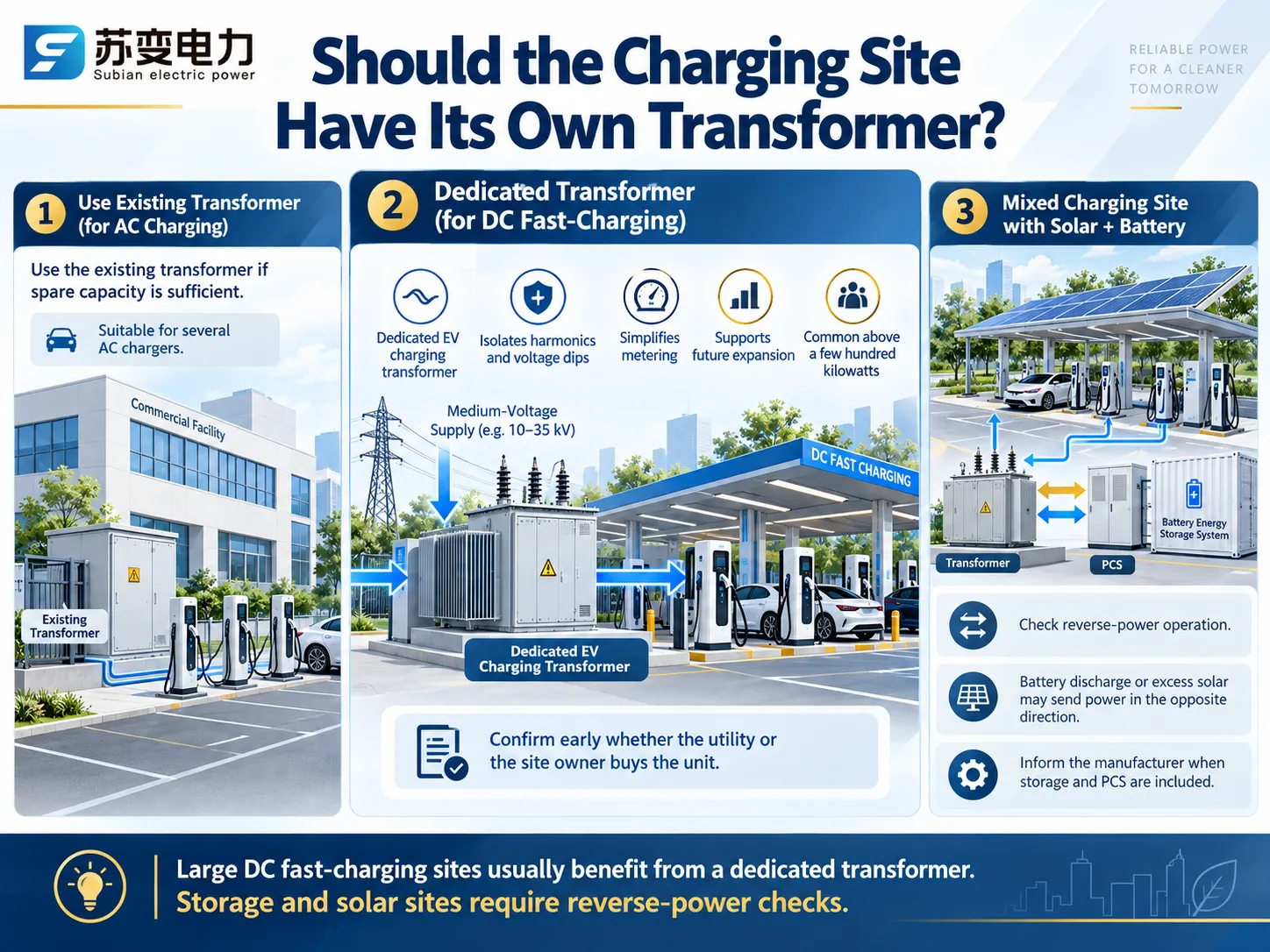
Should the Charging Site Have Its Own Transformer?
If a building has its own transformer that can supply enough electricity, several AC chargers can be connected to this supply. The U.S. multi-state grid study modelled a dedicated three-phase service transformer for every DC fast-charging site, and most utilities take the same view for anything above a few hundred kilowatts. A dedicated EV 충전 변압기에 직접적인 영향을 미칩니다. also keeps charger harmonics and voltage dips away from other customers, simplifies metering and lets the site grow without disturbing the building supply. Confirm early whether the utility or the site owner buys the unit.
In the case of mixed charging stations equipped with solar panels or batteries another check has to be performed. The transformer may also work in opposite direction in case when a battery discharges or when the power generated by solar panel exceeds the needs of the facility. Inform the producer about the specifics of the situation so that they can take them into consideration when designing the device. The article about the 에너지 저장 컴팩트 변전소 will tell you how storage, PCS and transformer work together.
Switchgear and Protection Around the Transformer
- MV side: a ring main unit with a load-break switch and fuses for smaller units, or a vacuum circuit breaker with a protection relay for larger ones, such as Subian’s XGN15-12 gas-insulated ring main unit 고체 VS1 indoor vacuum circuit breaker. Our ring main unit specification guide covers the options.
- LV side: a main breaker, an outgoing feeder for each charger or group, and surge protection. A draw-out board such as the GCS low-voltage switchgear lets individual feeders be maintained without shutting the site down.
- Residual current protection: IEC 60364-7-722 requires each charging point to be protected against DC fault current of 6 mA or more, either with a Type B RCD or with a Type A RCD plus a residual direct current detecting device complying with IEC 62955.
Which Current Transformers Does an EV Charging Station Need?
Current transformers are a separate decision from the power transformer, but they are specified at the same time. When people look for a current transformer for EV charging stations, they usually mean one of four devices, each with a different job.
| 위치 | CT 유형 | 목적 | 전형적인 사양 |
|---|---|---|---|
| MV incoming panel | Indoor bar-type or ring-type CT with metering and protection cores | Revenue metering and relay protection of the transformer feeder | 5 A or 1 A secondary; class 0.2S or 0.5S metering; 5P or 10P protection |
| LV main board and charger feeders | Window or bar-type LV CT | Site sub-metering and per-charger energy monitoring | Class 0.5S or 0.2S, ratio matched to the feeder current |
| Incoming supply of a home or small site | Split-core CT clamp | Dynamic load management, so the charger throttles before the main fuse overloads | The rating and output signal the charger maker specifies |
| Inside AC chargers | mA-range residual current CT, AC and DC sensitive | Detects DC fault current of 6 mA or more, as IEC 62955 requires | Built in by the charger manufacturer |
Metering CTs: Choose an S Class
Charging load is variable, being almost zero when there are no bays used while charging to full load when all bays are operational. Metering classes as per standards will guarantee accuracy of measurement starting from 5 percent of rated current and there are classes that cover extended range so called class S as per IEC 61869-2 that can measure down to 1 percent of the rated current. For example, Class 0.2S would keep accuracy of measurement within plus/minus 0.2 percent for current between 20 and 120 percent of the rated current and 0.35 percent for 5 percent of the rated current. Choose the ratio closest to the maximum which we expect taking into account that 120 kW DC charger at 400 V takes approximately 186 A, thus using 200/5 CT would be sufficient. Transformer used in our examples is rated for 800 kVA and full load current is approximately 1155 A thus 1250/5 CT is used.
Protection CTs on the Medium-Voltage Side
On the MV side, protection cores of class 5P or 10P feed the overcurrent and earth-fault relay. A 4 MVA depot transformer at 10 kV has a full-load current of about 231 A, so a 300/5 ratio leaves room for expansion. Subian’s LSY-10 integrated three-phase current transformer combines three cores in one unit for 10 kV switchgear, with primary ratings from 100 A to 1,000 A, metering classes 0.5 and 0.2S, and protection classes 5P and 10P. For wiring practice, see our guide to current transformer connection; for earth-fault detection on MV cables, our article on the 코어 밸런스 전류 변압기; and for budgets, the cost of a current transformer. Never leave a CT secondary open while the primary is energised.
CT Clamps for Dynamic Load Management
Many residential and small business users opt to install a charger even when they do not upgrade their electrical supply. What this means is that a split-core CT clamp is attached to the incoming energy source wire right before the supply begins to divide into various circuits. The clamp’s job is to provide the total current to the charger so that it knows when to start reducing its level of charging. In case of a three-phase supply, three separate clamps should be used, one for each phase, and they should be pointing in the direction from supply to load. The clamp itself should be the one recommended by the charger manufacturer.
Why the DC Side Uses Shunts, Not CTs
Generators of current employ the principle of magnetic induction and can thus only measure alternating current. DC power is measured with a shunt or Hall effect sensor in a DC energy meter; static DC meters of classes 0.5 and 1, included in IEC 62053-41, refer to electric vehicle charging stations measuring both the AC and DC sides. DC metering only bills for the energy delivered to the vehicle, while AC metering through current transformers reflects charger losses. Therefore, it is essential to find out what your charging service billing rules indicate.
EV Charging Station Transformer Specification Checklist
| 항목 | What to state |
|---|---|
| Charger list | Number, rating and type of every charger, AC and DC, plus any existing site load |
| Load assumptions | Coincidence or diversity factor, load-management scheme and a daily charging profile |
| 정격 | kVA, primary and secondary voltage, frequency, tap range, vector group and impedance |
| 고조파 | Charger current THD or harmonic spectrum, and any K-factor requirement |
| 구조 | Oil-immersed or dry-type, pad-mounted, kiosk or prefabricated substation, enclosure protection degree |
| 손실 | Maximum no-load and load losses, or the applicable efficiency regulation |
| Current transformers | Ratio, accuracy class, burden and secondary current for each metering and protection point |
| Site and power flow | Ambient temperature, altitude, flood and corrosion risk, and whether solar, storage or vehicle-to-grid will send power back |
| 표준 및 문서 | IEC 60076 or IEEE C57, IEC 62271-202 for prefabricated substations, IEC 61869-2 for CTs, test reports and drawings |
자주 묻는 질문
What size transformer does an EV charging station need?
The amount of that capacity running simultaneously, among other things, is determined by the amount and rating of the chargers. From the example worked out earlier, the demand is approximately 580 kVA, consisting of 4 120 kW DC chargers and 12 22 kW AC chargers working in the load management mode, after which it becomes an 800 kVA transformer according to IEC standards after applying a 20 percent margin.
Do EV chargers need a K-factor transformer?
There are exceptions, as chargers equipped with front-end rectifiers and distortion factors below approximately 5 percent can work properly with a regular transformer. Earlier six-pulse designs also allow for a K-rated transformer for North American operations or a transformer that meets the specified harmonic spectrum in IEC markets.
What current transformer is used in an EV charging station?
There are exceptions, as chargers equipped with front-end rectifiers and distortion levels below about 5 percent can successfully operate with an ordinary transformer. Earlier six-pulse designs enable the use of a K-rated transformer for North America or any transformer compliant with the required harmonic spectrum applicable to IEC markets.
Can a current transformer measure DC charging current?
No. A CT measures only alternating current. DC output is measured with a shunt or Hall-effect sensor in a DC energy meter, typically one built to IEC 62053-41.
참고 문헌
- IEEE 519-2022: Standard for Harmonic Control in Electric Power Systems
- IEC 62955: Residual direct current detecting device for mode 3 EV charging
- IEC 62053-41: Static meters for DC energy
- Harmonics (electrical power), Wikipedia
- Current transformer, Wikipedia
- 충전소, 위키백과
Choosing a EV 충전소용 변압기를 comes down to sizing on real demand, designing for harmonics and the daily load cycle, picking the form that fits the site, and specifying the current transformers that meter and protect it. Jiangsu Subian Electric Power Equipment Co., Ltd. designs and builds pad-mounted and dry-type transformers, prefabricated substations, 새로운 에너지 변전소 and integrated current transformers for charging hubs, car parks and fleet depots, configured to your network voltage and standard. Send your charger list, grid voltage and site conditions through our 연락처 페이지, 저희 엔지니어가 사이징 확인, 도면 및 공장 견적을 회신할 것입니다.