


It appears that transformers are capable of doing what should be impossible, as they adjust voltage without having any moving components and without an interference factor. The process of doing this involves preventing the two circuits from being connected, yet insisting that both circuits operate within the same magnetic field.
This simple configuration is the key to power supply systems being possible and to the fact that households located at a distance of 300km from an electric station are capable of having 230 V This is actually what allows electric power distribution system to function
A transformer consists of two coils that are wrapped around a shared magnetic core. In the primary coil, an electric current leads to the generation of a fluctuating magnetic field, which subsequently induces a current in the secondary coil. The turns ratio allows the definition of the voltages going through both coils, as, for example, 100 turns will go through 1,000 turns and that leads to the increase in voltage from 230 V to 2300 V.
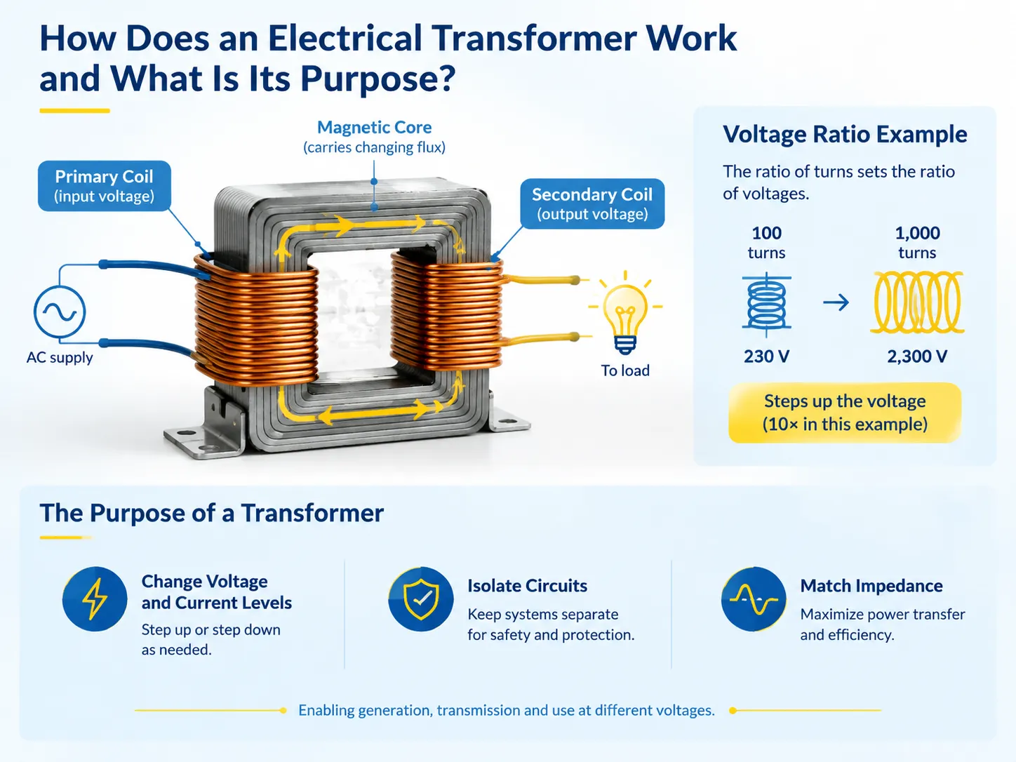
The Principle: Mutual Induction
Consisting of two coils and one core, the two components do not come into any electrical flow interaction with each other. If the primary part of the coils is provided with electrical energy, then an electric current is passed through it and generates an electromagnetic field. The current used in the circuit is an alternating one, therefore the field produced is continuously changing, leading to a linkage with the second coil; this results in an electric voltage appearing across the latter.
There are three main rules underlying the working principle of the transformer:
- The ratio of the windings of the transformer will determine voltage. Vp/Vs=Np/Ns.
- Twice as many windings will lead to twice as much voltage.
- Power is conserved. There is a principle of power conservation. Power input is equal to power output minus specific losses.
- The impedance is determined by the square of the ratio of windings. The transformer with the 10:1 ratio will appear as a 100 Ohm load for the primary coil.
The core is an important part. It is made of layered electrical steel, its orientation is in such a way that the field produced will travel with the help of this material, and layering the material will make it impossible to make closed circuits in the material.
Why It Only Works on Alternating Current
To initiate induction, there is a need for the flux that varies and changes with time. When you use direct current to create magnetic fields, that magnetic field does not change with time nor does it produce any voltage in a secondary coil. This outcome is possible because of the properties of electricity and not because of the transformer design itself. This phenomenon can be used practically in two ways.
First, the transformer works on alternating current and does not work on direct current. Therefore it has the ability to separate a direct current source from an alternating current system. Second, it explains why the transformer cannot be used for DC to DC conversion since this type of converter uses switching electronics to convert direct current to alternating current and vice versa.
Interestingly enough, the frequency itself plays a very important role. For example, a transformer designed for 50 Hz will get saturated at 60 Hz only if the voltage is proportionally decreased. A 60 Hz transformer used at 50 Hz voltage will be operating in the saturation mode and thus produce heat and noise.
What It Does in a Power System
Understanding the purpose of a transformer is easier achieved by tracking electric energy from the generating place to the socket.
The generator itself produces electricity of 11-25 kV, which is an economically viable insulation capacity of the generator. Thus, high voltage transmission of the energy is needed. The loss that the transmission is subject to is proportional to I²R, therefore rising the voltage by a factor of 10 will decrease the current by the same factor and will decrease the energy loss by 100. Thus, transmission makes sense because of that relationship.
When arriving at the destination, the high voltage goes down in steps: from 400 kV to 110 kV to 33 kV to 11 kV and finally to 400/230 V at the distribution transformer (the transformer serving the street or the building). Each step is a transformer and each transformer is used so that the stage could be built economically.
Thus, the purpose of the transformer can be divided into four functions that are often confused:
- Voltage transformation for transmission and for safe use
- Current transformation that follows automatically and allows high current to be transmitted at low voltage
- Galvanic isolation so either side of the transformer element cannot energize the opposite side and the system design could be supplied with ground independently
- Impedance matching and fault limiting, as data available indicates that the impedance of the transformer is created intentionally for the protection purposes.
The difference between the two main families in distribution work, and which one a project should specify, is set out in this comparison of power and distribution transformers.
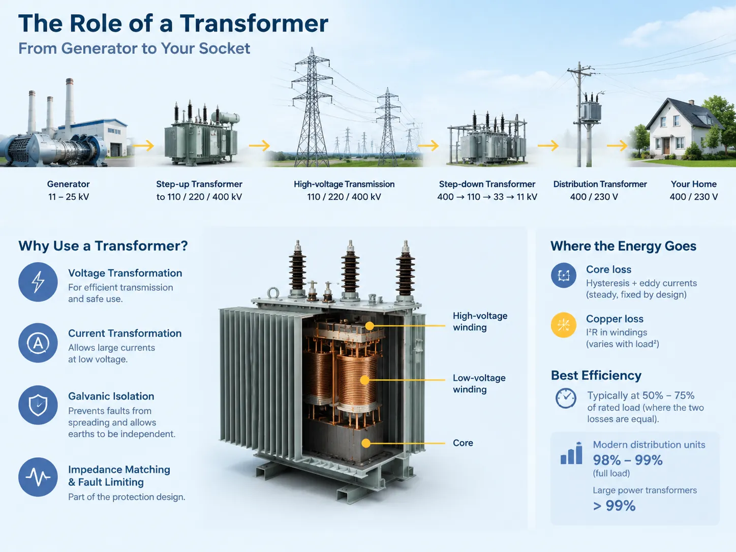
Where the Energy Goes
Transformers are practically never free from losses, but knowing the points where these losses occur provides one with considerable insight into their behaviour.
Core loss takes two forms. First, there is hysteresis (the magnetic domains flip) and second, there is eddy current loss (the currents circulating in steel). These loss occur whether or not a transformer is energized or under load, as they are inherent to its construction.
Copper loss with the resistance of windings is calculated as I²R. This means that at half-load this loss is one-quarter of full load loss.
Because one of these losses is constant and the other increases with the square of the load, the optimum efficiency of a transformer is observed at the load the losses are equal. Thus, if one loss increases with load, the other does not.
Transformation losses are constant during the entire operation; therefore, the efficiency of a transformer is the best when they are equal which is by design.The methods are described in this guide to testing a transformer.
The Main Types, and What Each Is For
Most of the offers that accompany the buyer come from four families of transformers.
The oil-filled distribution transformers are those which are either on poles or in pad-mounts. The oil acts both as insulation and as a coolant making these transformers compact and cheap for their capacity ranges of 25 kVA to 2,500 kVA.
The dry-type transformers use air and solid insulation instead of oil, which is usually made from cast epoxy resin. They are applied in the indoor conditions, in various constructions, tunnels, hospitals, and data centers, where the fire hazard of oil cannot be tolerated. Although dry-type transformers can cost more than oil-filled ones at the same capacity rating, they eliminate one risk type.
The power transformers are the big ones that are used in the transmission substations, designed for high voltage and throughput and a long life, fitted with load tap changers and cooling systems.
The remaining specialized units include instrument transformers which transform current and voltage for measurement or protection purposes, isolation transformers for the purpose of galvanic separation, autotransformers for the slight voltage change, and K-rated or harmonic transformers for the non-linear load operations.
The indoor case is where the choice is most often contested, and the classes, cooling codes and limits that decide it are covered in this overview of dry-type distribution transformers.
What It Cannot Do
There are three misconceptions that lead to real specification errors.
- It does not produce any power. A transformer increases voltage from 230 V to 2300 V by decreasing the current in the same proportions. Any claim regarding transformer capability of increasing the output power is an indication of a measurement error or fraud.
- It does not change the frequency. The input of 50 Hz yields an output of 50 Hz. To change the frequency one needs a rotating machine or a power electronics converter.
- It does not provide power factor correction. What the transformer does is that it exerts its own reactive demand without correcting anybody else’s; power factor correction is a job of either a capacitor or an active filter.
It also does not protect against everything. The transformer limits fault current through its impedance, and it is capable of separating the earths, but it does not disconnect the fault, limit the surge, and regulate the voltage unless it has a tap changer or an electronic regulator.
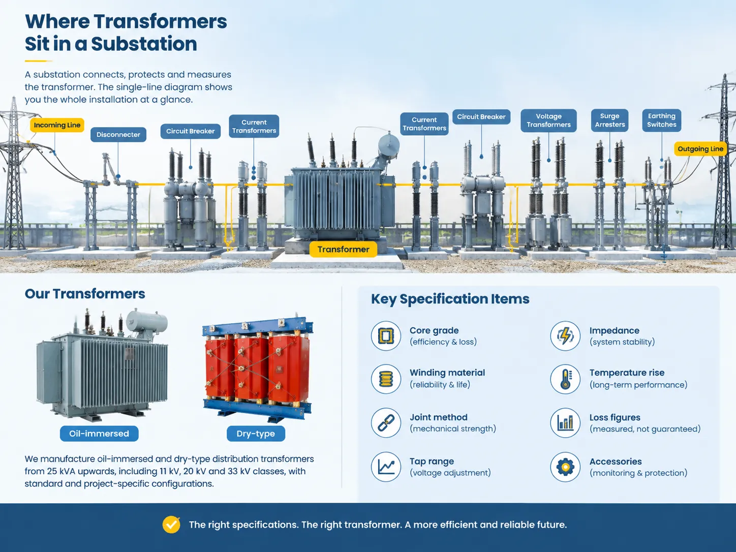
Where Transformers Sit in a Substation
It could be called a substation because all equipment serves the sole purpose of establishing connection, protection and measurement of the transformer, and the single line diagram is the best and quickest way to gain insight about the installation.
The circuit comes to a disconnector, then through a circuit breaker and current transformers, before it enters the transformer. The same is true for the outgoing path, suiting voltage transformers for metering, switch gears for protecting from impulses and earthing switches for facilitating maintenance. Each component exists because the transformer cannot do that.
That arrangement, and the ratings that go with it, is what an electrical substation components specification actually describes, and it is worth reading before buying a transformer on its own, because the transformer is rarely the item that delays a project.
What We Build
The company produces oil-immersed and dry type transformers starting from 25 kVA, including transformers with voltage ratings of 11, 20, and 33 kV for the markets of Asia, Africa, and the Middle East.
Specifications are boring. In fact, they include data like the type of the core, the type of wire and connection, the voltage range, and the extent of losses but not guarantees regarding them. All of that is written into the quotation instead of assumed, which is what our oil-immersed distribution range is built on.
In cases when specific loss levels are required for a project to meet certain efficiency regulations, the winding design and core grade must be selected to exceed those levels by a comfortable margin, because a transformer that achieves its goal of achieving 0.5% loss on the test floor does not guarantee a lifetime of holding within that margin for thirty years.
FAQ
Can you explain how a transformer works in a simple way?
There are two coils of wire which have a steel core but are separate from each other. The first coil has alternating current running through it that creates a variable magnetic field while the second coil turns that variable field back into current. A greater number of turns on the second coil increases the amount of current generated while a smaller number of turns will have the opposite effect.
Does every house need a transformer?
No single transformer for each house, such. The transformer that serves a home is generally serving a street or a whole building. It’s a pole-mounted or pad-mounted transformer that converts 11 kV or 33 kV to 400/230 V. The home needs a transformer dedicated only for cases where the incoming power line provides a different voltage, when there is a substantial load that requires a separate transformer, or where safety and noise issues require isolation.
What would burn out a transformer?
Frequent loading, a short circuit occurring on the secondary side, loss of cooling, low oil level present in the appliance, moisture being present in the insulation and a lightning surge reaching the winding. In practice the sequence is generally the same: overload or cooling problem occurring first is followed by breakdown of insulation. This involves the actions taken by the protective devices preventing the breakdown from occurring.
What is the 80% rule for transformers?
It is the practice of design, not the requirement of the code: operating a transformer at 80% of its rated power allows for room to accommodate ambient temperature, harmonics, temporary overloads, and future developments occultly, landing exactly in the best efficiency range. Related code rules are altogether different: the overcurrent protection device on the primary circuit is typically set at 125% of the rated current of the primary circuit; it is about protection of the transformer instead of about its loading.
References
- Ormazabal — How an Electrical Transformer Works
- ABB — Transformer Technology and Applications
- Siemens Energy — Power and Distribution Transformers
- Hitachi Energy — Transformer Fundamentals and Grid Applications
- Nynas — Transformer Oil and Insulation Performance
Conclusion
Two coils along with a core form a magnetic circuit, and that’s where the transformer starts. All the other devices and engineering challenges help to keep this technology running.
Inform us about the voltage ratio you are looking for, the rated power together with the application and loss level so that our specialists may select the necessary transformer design with cooling and impedance needed to suit your requirements.