


When you ask five engineers the distinction between a power transformer and a distribution transformer, you get five different answers. In one project, for instance, a 2,500-kVA pad-mounted will be called a distribution transformer, while in another project that same piece of equipment will belong to the category of small power transformers. This article will examine the definitions in the standards, the practical implications of those definitions, and how to identify the category into which a given transformer falls based on its nameplate, cooling class or a picture of the installation in question.
In a nutshell: A power transformer transmits high-capacity current from the transmission level to the sub-transmission level; its standard voltage levels begin at 33 kV and higher with a power level from 500 kVA to hundreds of MVA, and its construction operates at maximum capacity passing 90-100% load. On the contrary, a distribution transformer converts voltage from medium to low in the range from 35 kVA to 500 kVA with primary voltage of 11 kV to 35 kV and transformer secondary voltage about 230-480 V, and its operation is based on load levels from 50% to 75% because the load is not constant. The company Subian produces oil-immersed transformers of the distribution class and dry-type transformers, hence its product line mostly consists of distribution-class transformers.
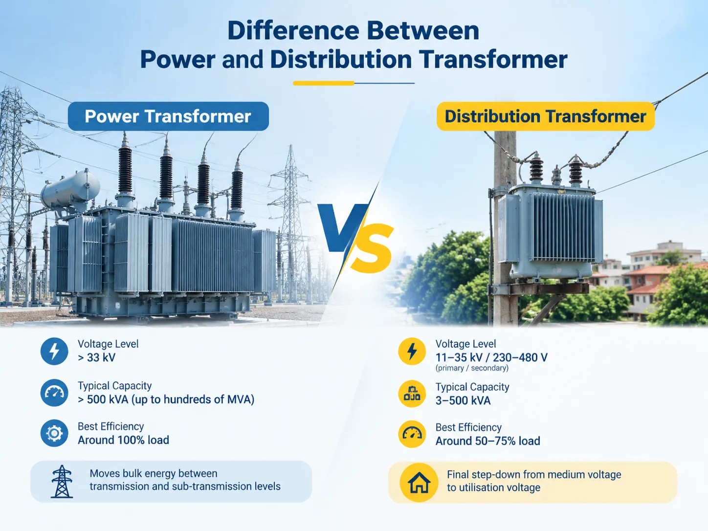
The clearest way to tell them apart: position in the chain
Forget about the nameplate for a second and focus on the location of the unit. The generation unit climbs up to transmission voltage level at the generation facility. The transmission unit carries out that voltage across the nation. Then, sub-transmission and primary distribution bring it down step-wise. The transformer that is responsible for the last decrease – the one that feeds a building or a street – is a distribution transformer irrespective of its kVA.
Everything before the last decrease, beginning from the generator step-up unit till the intertie substation, is a power transformer. It does not have a direct link to any consumer. The light does not diminish for a single person when a power transformer is switched on; however, for a whole region, it does. This single fact about its connection to the end-users explains almost every design deviation from duty cycle to importance given to the size of the unit.
Voltage and capacity: where the industry draws the line
IEEE 141 describes the traditional capacity splitting. According to it, the capacity for distribution type lies between 3 and 500 kVA while the power type covers all capacities starting from 500 kVA. Similarly, IEEE C57.12.00 standard, which states the general requirements for liquid-immersed transformers, has the same demarcating value for the type of transformers. It means that this remains the accepted standard, but there are slight deviations from it among manufacturers and the companies doing the actual work in the field.
| Parameter | Power transformer | Distribution transformer |
|---|---|---|
| Primary voltage | 33 kV to 765 kV | 11-35 kV (US classes 15 / 25 / 35 kV) |
| Secondary voltage | 33 kV to 220 kV at transmission nodes | 230-480 V (480/277 V, 208/120 V, 400/230 V) |
| Rated capacity | Above 500 kVA; commonly 5-500 MVA | 3-500 kVA per IEEE 141; up to 2,500 kVA in practice |
| Voltage class | HV and EHV | MV primary, LV secondary |
| Where it lives | Generating stations, transmission substations, interconnections | Poles, pads, vaults, indoor electrical rooms |
| Who it serves | Networks and utilities | End users, buildings, light industry |
In this domain, the category of voltage is seen as the most reliable tool of identification. If the secondary voltage being utilised falls in the ranges of utilisation voltage, we are dealing with a distribution transformer. On the contrary, should both the windings be operating at the transmission level, we are dealing with a power transformer, even though the drawings may indicate it to be very small in size.
Duty cycle and efficiency: the difference that actually costs money
People underestimate the importance of the iron and copper losses almost completely. Iron (no-load) losses occur continuously 24 hours a day, and copper (load) losses depend on the square of current instantly. Power transformers work very closely to their nameplate ratings continuously, that is why the designer equates copper and iron losses at maximum load and makes the flux density high enough to decrease the core. Distribution transformers work continuously but provide energy only during peak hours, that is why the designer works on minimizing iron losses and accepts the fact that copper losses will prevail at maximum load. The efficiency of distribution transformer makes it somewhere around 50%-75%.
As a result, the ordinary efficiency calculated by the means of full load is totally wrong for the distribution device. All-day efficiency calculated as total energy outputs for 24 hours divided by total energy inputs of the transformer is the better option for this situation. The 100kVA transformer which has 300W of iron and 1,200W of copper losses at full load can demonstrate 98.7% of all-day efficiency over the realistic load cycle despite the fluctuating instantaneous efficiency.
That is why power and its correct sizing is of utmost importance on the distribution side than normally expected. If the unit is oversized, iron losses operate on the unit which never works. If the transformer is undersized, copper losses bring penalties every peak.The load profile, not the peak demand alone, is what should drive the kVA selection, and a proper load calculation will usually land on a smaller unit than connected load suggests.
Design differences you can see and measure
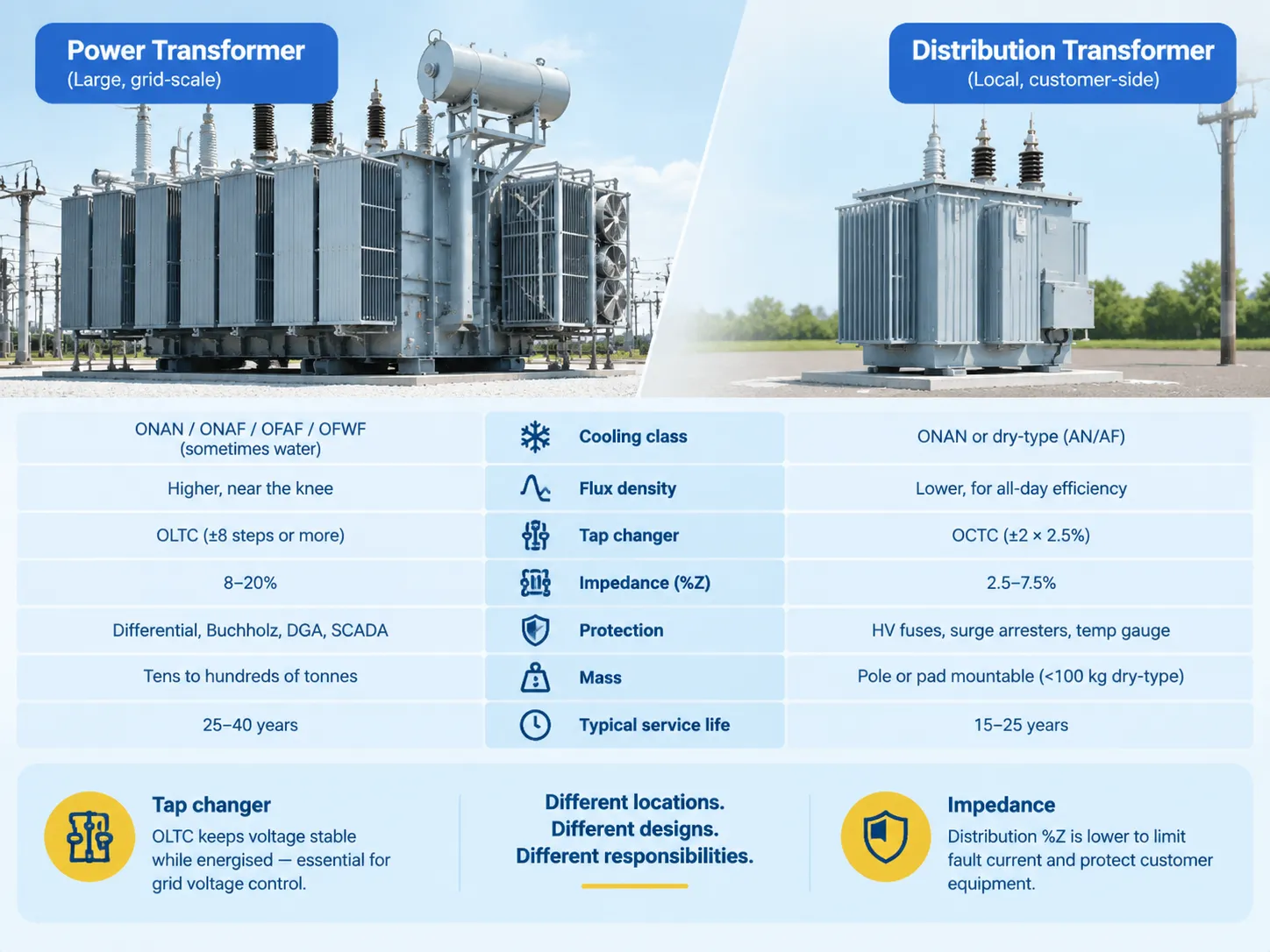
When approaching a transformer, one can see the many design elements. Power transformers are large, oil filled containers equipped with conservators, radiators, breathers, and sometimes multiple cooling methods, starting with natural cooling known as ONAN, and moving on to ONAF, OFAF, or OFWF depending upon the load and surrounding temperature. Which of those two families you end up with is often decided by where the unit stands rather than by the load, because oil-immersed and dry-type transformers carry completely different fire-separation and maintenance obligations.
| Design aspect | Power transformer | Distribution transformer |
|---|---|---|
| Cooling class | ONAN / ONAF / OFAF / OFWF, sometimes water | ONAN or dry-type (AN/AF) |
| Flux density | Higher, running near the knee of the B-H curve | Lower, traded against all-day efficiency |
| Tap changer | On-load tap changer (OLTC) common, often ±8 steps or more | Off-circuit tap changer (OCTC), typically ±2 × 2.5% |
| Impedance (%Z) | Selected for fault coordination and grid stability, often 8-20% | Selected to limit fault current and control voltage drop, commonly 2.5-7.5% |
| Protection | Differential protection, Buchholz relay, DGA, SCADA integration | HV fuses, surge arresters, temperature gauge, occasional remote sensing |
| Mass | Tens to hundreds of tonnes on permanent foundations | Pole or pad mountable, occasionally under 100 kg dry-type |
| Typical service life | 25-40 years | 15-25 years |
The first of these rows deals with tap changer: an OLTC means the transformer can control voltage while energised, which is useful if a unit needs to control the voltage profile in the entire region. For the distribution transformer it will be set at commissioning and then forgotten, since nobody would want to disconnect a neighbourhood just to adjust the tap during the peak load.The next row discusses impedance. Its value is chosen so that fault current reaching customer’s service equipment is limited. This is also the reason %Z for 500 kVA units is typically lower than that for the same-size power transformer.
Types and sub-classes on each side
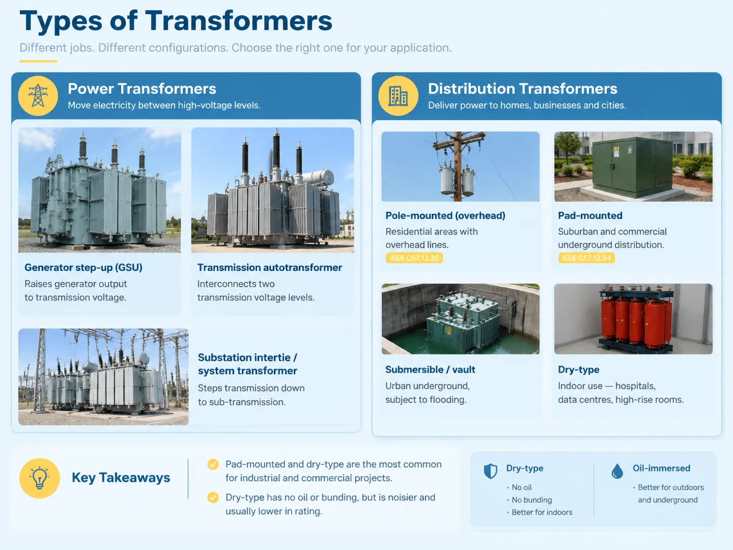
Neither category is monolithic, and the sub-classes tell you what the unit is for before you read a single rating. Pad-mounted and dry-type distribution transformer configurations account for the large majority of industrial and commercial enquiries, so those are the two rows worth knowing properly.
| Class | Common types | Typical use |
|---|---|---|
| Power | Generator step-up (GSU) | Raises generator output to transmission voltage |
| Transmission autotransformer | Interconnects two transmission voltage levels | |
| Substation intertie / system transformer | Steps transmission down to sub-transmission | |
| Distribution | Pole-mounted (overhead) | Residential areas with overhead lines; IEEE C57.12.20 |
| Pad-mounted | Suburban and commercial underground distribution; IEEE C57.12.34 | |
| Submersible / vault | Urban underground, subject to flooding | |
| Dry-type | Indoor use — hospitals, data centres, high-rise electrical rooms |
The dry-type row is also important. There is no oil to ignite firstly and no bunding needed, making dry-type distribution transformers the best candidate for indoor use where a liquid-filled transformer would have to comply with fire separation rules. The downside, however, is the noise level and the fact that dry-type transformers are mostly meant for lower ratings in the same footprint. Therefore, it is usually the building code and not the engineer that decides on putting a dry-type transformer over a liquid-filled one.
Standards and testing: what changes with the class
Classes have the same origins, though their contents differ from one another. IEEE C57.12.00 deals with the basic requirements for liquid transformers. IEEE C57.12.10 is intended for power transformers while IEEE C57.12.20 is meant for overhead transformers and IEEE C57.12.34 is meant for pad-mounted transformers. Internationally the role of these documents is undertaken by IEC 60076 and ANSI/IEEE standarts are being referred to in case of American utility involvement.
There are two regulatory actions that may be taken with respect to a distribution equipment that are very rarely addressed in case of power #transformer #specification. The first one is energy efficiency regulation; in the USA the DOE energy efficiency regulations apply to distribution equipment and the reason is that it is necessary to indicate tested no load and load losses with the relevant tolerances. That wording turns a transformer specification sheet into a contractual document rather than a brochure, and the guaranteed loss figures are what the factory test gets measured against.Another benefit is that the production of the distribution units is carried out in bulk so that they are subject to the same compliance for all usages as opposed to having to undergo different on-site verifications. This leads to the fact that it is much more important to obtain the certificate of tests than to get a marketing brochure.
Whatever type you are purchasing, you need to request the routine testing list according to the specifications: ratio and phase relationship parameters, short-circuit impedance (impedance measurement), no-load losing, load losing, and insulation resistance values. Ask for the actual routine testing certificate that corresponds with the serial number as opposed to a type testing report issued for the family of products.
Where the boundary genuinely blurs
Here are three points which make the 500 kVA line confusing for people involved in production assistance.
First, large distribution. Utilities do order 1,000, 1,500 or 2,500 kVA pad-mounted transformers in any distribution feeder. By IEEE 141 definition, these units are classified as power transformers, but their functional, installed capacities and design intentions should suggest that they belong to distribution transformers category. Generally speaking, one can say practice in the USA is more focused on functionality than classification.
Second, step-up transformers on generating facilities. For instance, a 1,500 kVA transformer that steps up voltage from 480V to 13.8 kV at a solar facility can be either power or distributions transformer. It all depends on specification made by a customer with regards to required operational features of a unit including cooling class, presence of tap changer, level of impedance, etc.
Third, vector groups and interconnection. Once you are paralleling transformers, vector group compatibility becomes the governing constraint regardless of class, so two units of similar rating from different classes can be electrically incompatible while two units from different decades sit happily in parallel. Get the vector group wrong and the circulating current will find it, so this is a configuration question, not a class question.
Which one do you actually need?
Start with the load’s requirements. If the secondary voltage corresponds with the one used by the equipment, you will need to use a distribution transformer, which means that the process of its selection will be a simple calculation based on the load profile, where through the kVA, one can evaluate the peak load, future growth of the load, and choose the cooling system and mounting solution.If at both sides of the transformer the voltage is the current voltage, then the transformer is considered a power transformer because the unit’s main purpose is connecting the systems rather than fulfilling its function as per the load. This means that the specification process will depend on fault level and impedance.
There are two major mistakes that are usually made while buying a transformer: the first is buying an undersized transformer that is unable to serve peak loads, and the second one is buying a unit on power transformer specifications, when actually it is possible to buy a distribution transformer, which will also cover the load.
The problem can be avoided by conducting a thorough study before making any purchasing decisions.
Subian produces a range of products in the segment of distribution equipment such as distribution transformers, instrument transformers, and neutral grounding systems. The company has no power transformers in stock and we will inform the clients about it in case of a project that needs one. In case when there is a necessity to create a load profile, we will fulfill this requirement together with the necessary test results.
FAQ
What are the four main types of transformers?
There are four well-known categories of transformers based on their working principle. The classification more helpful to buyers segments transformers into power transformer, distribution transformer, instrument transformer (current and voltage) and dry-type transformer. In most cases industrial projects involve the use not of power transformers but of the last three transformer types.
What is the purpose of a distribution transformer?
This stage performs the last stage of reduction of voltage before electricity reaches the end user as it steps down medium voltage from the distributor to a utilization voltage like 480/277 V, 208/120 V or 400/230 V. Since it connects directly with the loads here, it is designed to be efficient at any point in the load curve that varies from a few percent to full rating every day.
What’s the difference between a transformer and a power supply?
A transformer alters alternating current (AC) voltage relying on electromagnetic induction only; it does not do anything else since transformers do not provide regulated output or rectified electricity, which only brings altered AC voltage. A power supply employs a transformer or a switching stage together with components responsible for the processes of rectification, filtering, and regulation; thus, it is capable of generating electricity of required quality to ensure that electronics can receive constant input signal.
What are the different types of distribution transformers?
Overhead units are designed to be mounted on poles, pad-mounted types to be used in underground distributions, vault or submersible types can be employed for said purposes, and dry types can be used indoors. Another aspect is that all of these categories have single-phase and three-phase types. The preferred type of mounting is often decided by the locality, the specifications and requirements for the unit, as well as the practices of the local utility.
Can a distribution transformer be used as a power transformer?
Not in a safe way while moving backwards. A distribution unit is not constructed for the voltages, short-circuit currents and continuous load application of transmission installations. A failure in design will lead to an emergency when one is used here as the impedances and protection settings of the other elements will be not valid.
Does a power transformer always have an OLTC?
Generally, however not always. On-load tap changing is prevalent as power transformers frequently regulate the voltage status of the entire network. Some intertie and generator step-up units use off-circuit tap changers or fixed ratios combined with additional regulation, making the OEM specifications the only firm reference source.
References
- IEEE — C57.12.00 General Requirements for Liquid-Immersed Distribution, Power and Regulating Transformers
- IEEE — C57.12.20 Overhead-Type Distribution Transformers
- IEEE — C57.12.34 Pad-Mounted Compartmental-Type Distribution Transformers
- IEEE — IEEE 141 Recommended Practice for Electric Power Distribution for Industrial Plants
- IEC — IEC 60076 Power Transformers series
- US Department of Energy — Distribution transformer energy conservation standards
- UL Solutions — Transformer listing and certification reference
Conclusion
The simplified interpretation indicates that a:Transmission transformer connects systems at transmission voltages and is tailored for continuous use at full capacity;Distribution transformer completes the final reduction of voltage before distribution and is designed for varied usage;While size provides a decent guide at a level of 500kVA, it is actually voltage category and duty cycles that prove to be the best references in practice.
In most cases, however, the real work of users takes place on the distribution side where the issues behind matching the transformer to load profile, cooling and mounting set-up as well as checking losses against the set efficiency requirements is performed. If you deal with a project of 1,000-2,500 kVA that oversteps the line between the two categories, make sure you get the specification written according to a function rather than type, and demand a routine testing certificate prior to releasing the equipment from the factory.