


In a typical scenario, an HVAC technician contacts the experts to share about a new rooftop unit with a voltage rating of 230 volts but it has been receiving a constant voltage supply of only 208 volts, causing frequent tripping of the compressor due to voltage drop. The solution turns out to be quite a simple task taking 20 minutes and costing around $200; there is a simple device, a small little box bolted next to the disconnect that boosts voltage to 230 volts, known as buck-boost transformer. Buck-boost transformers are not well understood as well as quite confusing as it has a compact look similar to a transformer but does not perform in the same manner.
This post serves as a practical guide to understanding the possible problems solved by the buck-boost transformers, working of an autotransformer, capacity of a 1kVA transformer to withstand a load of 9.5kVA, working principles of buck-boost transformers in single and three-phase systems, their construction based on the differentiation among isolation transformers, distribution transformers and other relevant problems facing users, including potential voltage surge due to the open neutral in existing four wire systems.
In conclusion, a buck-boost transformer is a type of autotransformer that is utilized to make small variations in voltage (from 5 percent to 20 percent, for instance, from 208 V to 230 V or from 240 V to 208 V) that is typically used for electrical equipment such as motors, HVAC equipment, or foreign-made appliances. In most cases, just the change in voltage is passed on to the transformer windings; this is because the kVA rating of the transformer is calculated based on the difference between the output voltage and the regular secondary voltage, which means that a kVA transformer operating at 208 volts and boosting to 230 volts can be operated at a load of about 9.58 kVA. The buck-boost transformer operates very efficiently (97 to 99 percent) and is assumed to have a life span of 20 to 30 years, whereas it has no isolation, as well as low voltage stabilization range.
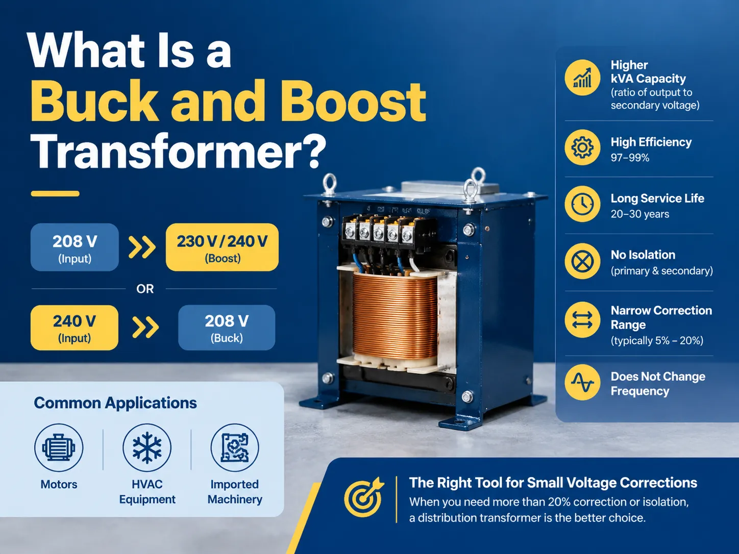
What a Buck and Boost Transformer Actually Does
Two tasks and a single name define the device because it is the same unit with two different wire arrangements.
- The term boost refers to the provision of voltage. The secondary windings are wired in phase to the primary to get output as input and the voltage across the winding. For instance, 208 volt supply changes to 232 volts when there is a 24 volts in the secondary coil.
- Buck refers to getting rid of voltage. The secondary coils are wired in reverse, and the output is given by input voltage subtracting the winding voltage. By connecting 240 volts to the equipment, the output voltage would be 208 volts when there is 32 volts in the winding and so on.
This is the whole concept. It works on the principle of voltage trimming. Under this principle of operation, no creation of power happens, neither there are any changes in frequency or phase.The main advantage of having the device is that North American voltage distribution is anything but standardized when people think differently. In North America nominal voltage values such as 208 V, 240 V, 480 V, or 600 V refers to a range of voltages based on transformer tap position, length of power lines and load condition. For instance, a building located at a longer distance from the power station may have the voltage of 197 V when the load is heavy and may have 213 volts when it is light.
If you want the vocabulary that surrounds these ratings — turns ratio, impedance, temperature rise, taps — transformer specifications explained is worth reading before you spec anything, because a buck-boost is specified differently from every other transformer in the catalogue.
Why a 1 kVA Buck-Boost Can Carry 9.5 kVA
This is the section that perplexes the buyers the most and is also why buck-boost transformers may seem quite tiny for the job they do.
In isolation transformers, the entire load power is transformed by means of the core magnetically. This means the 10-kVA load requires a 10-kVA transformer. However, in an auto transformer, the loading of primary and secondary windings takes place with one winding for both. It is worth noting that only the difference of voltage undergoes conversion since the maximum electrical power passes from input to output without conversion at all. The practical formula here would be:
Load kVA = Transformer kVA × (Output voltage ÷ Nominal secondary voltage)
A simple example would be the case of powering 208 V with the 1-kVA buck-boost with a 12/24 V secondary connected for 24 V.
The logic reads as follows:
230 ÷ 24 = 9.58, which means that the 1-kVA transformer performs for a load of 9.58 kVA. It is worth noting how the 27-lb box operates under the load which, in other cases, would require a 10-kVA isolation transformer.
The same principle is also applicable while doing bucking. If you use the same device but decrease 240 V to 208 V it will give you 208 ÷ 24 = 8.67, which provides 8.67 kVA of load from the device of 1 kVA.
| Application | Input → Output | Winding used | Multiplier | Load from 1 kVA unit |
|---|---|---|---|---|
| Boost HVAC / motor | 208 V → 230 V | 24 V | 9.58× | 9.58 kVA |
| Boost to 240 V | 208 V → 240 V | 32 V | 7.50× | 7.50 kVA |
| Buck to 208 V | 240 V → 208 V | 32 V | 6.50× | 6.50 kVA |
| Buck to 208 V | 240 V → 216 V | 24 V | 9.00× | 9.00 kVA |
| Buck imported machinery | 480 V → 380 V | 100 V | 3.80× | 3.80 kVA |
| Buck motor supply | 480 V → 460 V | 20 V | 23.0× | 23.00 kVA |
The last line is the reason why buck-boost transformers can be found in almost all old industrial plants. The drop from 480 V to 460 V for matching the motor’s nameplate voltage is a decrease of 4%, resulting in a huge multiplier and a very small unit.
Correct sizing means going in the opposite direction from how one sizes transformers. The required load kVA is based on the actual load connected because getting this wrong can multiply that mistake. Continuous versus noncontinuous duty and starting current of the motor then define whether the device runs cool or hot.
Single-Phase and Three-Phase Systems Behave Differently
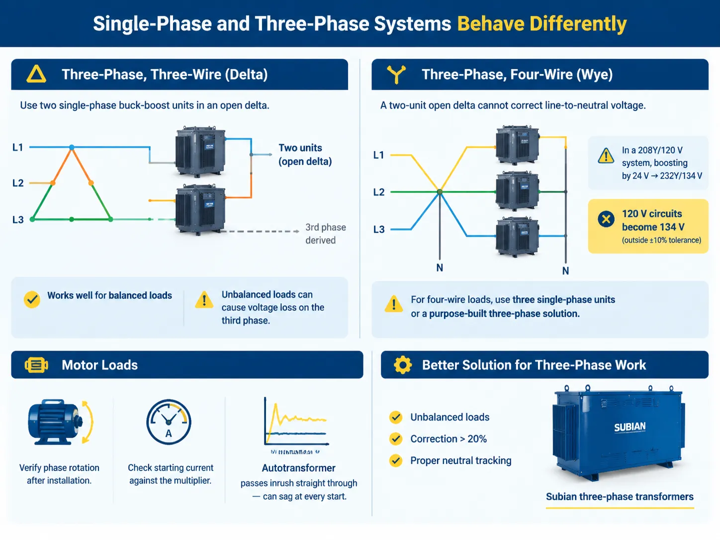
order to provide a three-phase supply, buck-boost transformers are linked together whereby proper means of connection is heavily reliant on transformer configuration.
A delta three-phase, three-wire circuit consists of two single-phase devices connected to give an open delta configuration. This arrangement allows typical phase on utilization of two units while deriving the third phase which is acceptable in case a balanced load is used. However, unbalanced loads can lead to failure in the third phase hence ensure proper load assessment before going ahead with this design.
A wye three-phase, four-wire circuit does not give any electric advantage when using two single-phase transformers in an operation. In fact, an open delta arrangement would not work in a four-wire system, which includes high majority of 120 V loads supplied from a 208Y/120 V panel. In 208Y/120 V system when all three phases are boosted by 24V and converted to 232Y/134 V, provides unacceptable voltage delivered to the load i.e. 134 V to the unit which is not compliant to the 10% deviation standards from the tolerances set by most of the companies when working with buck-boost transformer.
Assessing motor loads with consideration of buck-boost transformer requires the checking phase rotation based on equipment type and starting current based on inrush current type being used. Autotransformer enables avoiding the enormous amount of starting damage via proportionate passing of inrush. As a result, under-sizing of transformer can be forgiven in the case of generator operation.
Three-phase work in general is where a purpose-built unit usually wins. Subian manufactures three-phase transformers for exactly the cases where an open delta of two little buck-boost units stops being the sensible answer — when the load is unbalanced, when the correction exceeds 20%, or when you need a neutral that tracks properly.
How Buck-Boost Transformers Differ From Other Transformers
| Property | Buck-boost / autotransformer | Isolation transformer | Distribution transformer |
|---|---|---|---|
| Winding relationship | Shared (autotransformer) | Separate primary and secondary | Separate primary and secondary |
| Typical voltage change | 5–20% | Any ratio | Any ratio, fixed |
| kVA for a given load | Small fraction of load kVA | Equal to load kVA | Equal to load kVA |
| Galvanic isolation | None | Yes | Yes |
| Neutral handling | Does not create a new neutral | Can create a separately derived system | Can create a separately derived system |
| Harmonic attenuation | None | Some | Some |
| Typical size range | 0.05–10 kVA single-phase | 0.5 kVA to several hundred kVA | 15 kVA to 10 MVA+ |
| Typical cost | $80–$2,500 | $400–$15,000 | $2,000–$200,000 |
What makes difference in functionality is neutral. The buck-boost transformer does not supply a new neutral and does not provide a separately derived system. This transformer only alters the voltage of the existing system. Meanwhile, the distribution transformer generates a whole new system, which also has its own grounding and bonding point.If you need a 480 V delta system converted to a 208Y/120 V system with a proper neutral, you need a distribution transformer — the physics of how distribution transformers are built and where they sit on the network is a completely different design exercise.
Let’s put this simply: isolation is vital when it is needed. A buck-boost transformer does not prevent any primary-side disturbances from reaching the load and does not lower the fault current or help interrupt a ground loop. In case your purchase is driven by any of the issues related to noise, surges, or ground loops and not by voltage mismatch, you are in the wrong place.
The Downsides You Should Know Before You Buy
Buck-boost transformers do one specific job well. The problems arise when these devices are used for something other than that specific job.
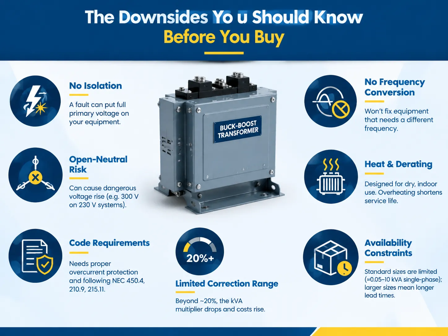
- Without isolation, fault containment is gone. Since the windings are in common, a short on either side can apply the primary voltage to the load. This explains why autotransformers are not used in certain situations and that buck-boost transformers are not appropriate for providing power to personnel and sensitive equipment unless an added level of protection is employed.
- Problems associated with open neutral in four-wire systems. This is a big one. When buck-boost transformers are used in a three-phase four-wire system and the neutral comes loose on the input side, the voltage will redistribute, and the secondary will see a voltage rise above normal. Equipment designed for 230 V can be destroyed by 300 V this way. If buck-boost transformers are connected to a wye system, the neutrality will be an important safety issue instead of a minor detail.
- Requirements of the NEC regarding branch circuits and feeders. NEC 450.4 requires that transformers have overcurrent protection, and that applies to auto transformers. Around Article 210.9 and 215.11 provide unique requirements regarding the use of autotransformers in power feeding branch circuits and feeders. The practical upshot is that a buck-boost installation needs the protection scheme designed, not improvised — the same discipline that keeps transformers from failing early applies here, and voltage correction gear is more sensitive to it than most, because the fault window is small and the consequences are immediate.
- It should be remembered that outside the 20% range of correction, kVA multiplier falls off and the economy turns upside down. It means that if you want to boost 208 volts to 277 volts (33% correction), you end up with a multiplier of 4.6 which means that a small load will need surprisingly big equipment, at the moment when utilizing an isolation transformer becomes a safer and cheaper option.
- Inability to convert frequency. There is a significant difference: a machine operating at 50 Hz and supplied with 60 Hz from North America requires a frequency converter, not a transformer. In other words, customers purchase buck-boost devices to solve the problems with imported machines only to find out that the transformer could be effective only in half of the cases.
- Heat and derating. These units are usually built to withstand Class H conditions (180°C) with maximum temperature rise of 115°C. If you put the unit in the ceiling plenum without any ventilation, you will reduce its service life.
- Availability of devices. Units are available at starting point of approximately 0.05 kVA up to 10 kVA for single-phase applications. If any deviations from standard sizes appear, waiting times will exceed normal limits.
Where Buck and Boost Transformers Actually Get Installed
The list of applications is brief and very precise. If you do not find the issue you wish to solve on it, you should seek other sources.
| Application | Why buck-boost fits | Typical size |
|---|---|---|
| Rooftop HVAC on 208 V system | Unit nameplate 230 V, supply is 208 V | 1–3 kVA |
| Motor nameplate matching | 480 V supply, 460 V nameplate | 0.5–5 kVA |
| European machinery on 600 V or 480 V supply | 380–400 V imported equipment | 3–10 kVA |
| Lighting and controls voltage trim | Long feeder with chronic low voltage | 0.5–2 kVA |
| Small 3-phase loads needing 480 V | Boosting 240 V up to 480 V | Two units, open delta |
| Solar inverter output matching | Trimming inverter output to the point of interconnection | Project-specific |
One should note the omissions in the list: any case of using a new neutral, that of insulating the current system, any deviation requiring more than one per cent of correction, and lastly, cases with unbalanced three-phase load.
What Buck-Boost Transformers Cost
The rates shown below are the usual trade rates for single-phase units in the US and the EU, open or closed, and are influenced by the developments concerning copper and steel and are expected to change depending on the timing of purchase.
| Rating | Typical price | Common use |
|---|---|---|
| 0.05–0.25 kVA | $60–$120 | Controls, small lighting circuits |
| 0.5 kVA | $90–$180 | Single motor trim |
| 1 kVA | $150–$280 | Up to ~9.5 kVA load at 208→230 V boost |
| 2 kVA | $250–$450 | Small HVAC, pumps |
| 3 kVA | $350–$600 | Rooftop units, small machinery |
| 5 kVA | $500–$900 | Larger HVAC, imported equipment |
| 7.5–10 kVA | $900–$2,500 | Heavy single-phase loads |
If one compares the two devices, the difference in terms of the respective expenses involved becomes apparent: A 9.58 kVA isolation transformer or distribution transformer is priced at several thousand dollars and weighs more than a hundred pounds, while a 1 kVA buck-boost transformer doing the same job only costs less than $300 and can be moved by one person.For the wider spread across transformer classes, how much an electrical transformer costs breaks it out by type and rating, and the pattern is consistent: the more isolation and the larger the correction, the steeper the curve.
FAQ
What are the downsides of a buck-boost converter?
There are four real drawbacks. First of all, there is no isolation between primary and secondary, which exposes the load to the primary voltage in case of short circuit. Second, the range of correction is limited — it is around 5%-20% and efficiency drops outside of it. Thirdly, and the most critical, in a three-phase four-wire system an open primary neutral leads to voltage rise on the secondary, which can damage equipment connected to it. Therefore, the neutral connection needs to be considered as important! Finally, buck-boost cannot change the frequency and create a new neutral or separately derived system. In other words, it cannot convert 50 Hz to 60 Hz or generate 120 V from 480 V delta feed. If you meant a DC-DC buck-boost converter, like the ones used in power electronics, the situation is quite different since now we deal with switching losses and EMI instead of transformer issues.
When to use a buck-boost transformer?
One should apply this in an occurrence of all three of the following situations: the voltage mismatch is not significant (less than 20%), the load itself does not demand isolation form the supply, and the required correction does not involve creating a new system. A textbook example would be a load rated at 230 V working on a supply of 208 V, or motors rated at 460 V operating on a 480 V system. Another application could be fixing a chronic case of low voltage due to a long feeder, but don’t do this where a new neutral needs to be made, where isolation is needed, when frequency conversion is necessary, or when the load is a sensitive electronic system which has its own conditioning issues.
What is the difference between buck and boost transformers?
The difference in wiring is not due to the product difference. The transformer is called as “boost” when the secondary is connected in synchrony with the primary making a sum of voltages, and “buck” when the secondary is attached in a way of cancelling out the voltage. The transformer having primary of 120 × 240 V and secondary of 12/24 V will be 208 V to 232 V booster in case of one installation order but will become 240 V to 216 V bucker in the opposite case. Manufacturers give the same designation in one catalogue for both options so the responsibility for the type of usage lies on the installer as he defines it. It is even possible to reuse the same machine in the future because it will not change at all.
What is a buck-boost transformer for 120 to 240 volts?
There is no such thing as a buck-boost transformer that converts 120 volts to 240 volts. If someone tells you different, that person is trying to sell you something. A buck-boost transformer only gives you a 5% to 20% change in regulation, while converting 120 volts to 240 volts is a 100% delta requiring a 2:1 isolation transformer, an autotransformer with a 1:1 approximation on top, or a dedicated step-up transformer. When people search for this, they either want a transformer that works with a primary voltage rating of 120 V and a secondary voltage rating of 12 V or 24 V that is used for making small corrections, or they need to use a 240 V device with only 120 volts of supply voltage and need to do a step-up transformation. To solve the last issue, ensure you select a transformer with an actual 1:2 ratio and verify the grounding and neutral connections of the load being supplied.
References
- NFPA 70 — National Electrical Code, Article 450 (Transformers and Transformer Vaults), 210.9 and 215.11
- UL Solutions — UL 506 Standard for Specialty Transformers
- NEMA — Transformers, Regulators and Reactors Standards
- IEEE — C57 Series Standards for Transformers and Regulators
- U.S. Department of Energy — Motor Voltage Tolerance and Efficiency Guidance
- Acme Electric — Buck-Boost Transformer Application and Selection Data
- Eaton — Transformer and Voltage Correction Technical Documentation
Conclusion
A buck-boost transformer designates equipment dealing with voltage corrections rather than being a transformer in the full understanding of the term. It solves voltage problems by correcting it by 5%-20% with the help of equipment costing much cheaper and smaller than an isolation transformer. The kw rating of this transformer corresponds to 9.58kVA for a transformer rated 1kVA, despite the situation being that the buck-boost transformer is manufacturing in compliance with the same standards used for proving that the constant voltage increase by 33% does not make sense.
When speaking about the advantages of using a buck-boost transformer, it should be added that there are three major groups of issues that have to be taken into account. First of all, one has to ensure that a right size of the end user’s device is chosen and the relevant factor is verified, as even minor miscalculations related to loading can lead to several serious problems. Secondly, while operating on 3-phase supply connection, the neutral point of the initial circuit should be treated appropriately, so that the connection would be safe for equipment.Last but not least, when making a choice, honesty has to become the major factor.