


The installation of the wind turbine on a location is just one thing. After an electrical power is generated at a wind turbine, electrical immediate goes through at least two step-up transformers and a substation that almost no one sees after that. The hidden path is where the various types of engineering decisions are made for the people involved in planning, building or purchasing wind turbines.
The Explore a Wind Turbine information paper by Department of Energy presents an overview of electricity generation using wind power. It states that each turbine at a wind farm invariably generates electricity and sends it to a substation before it reaches the grid. What is hidden is what is done to produce this system. It needs to be comprehended what type of transformer is used at the wind turbine, what type of transformer is used at the main substation, why energy is collected at 33kv in one country and at 34.5kv in the others, and what requirements should be taken into account for the EPC contractor.
This paper fills the gap in the information above as it describes the complete electrical system of a wind farm starting from the generator terminals and finishing with the connection point providing all necessary calculations and lists.
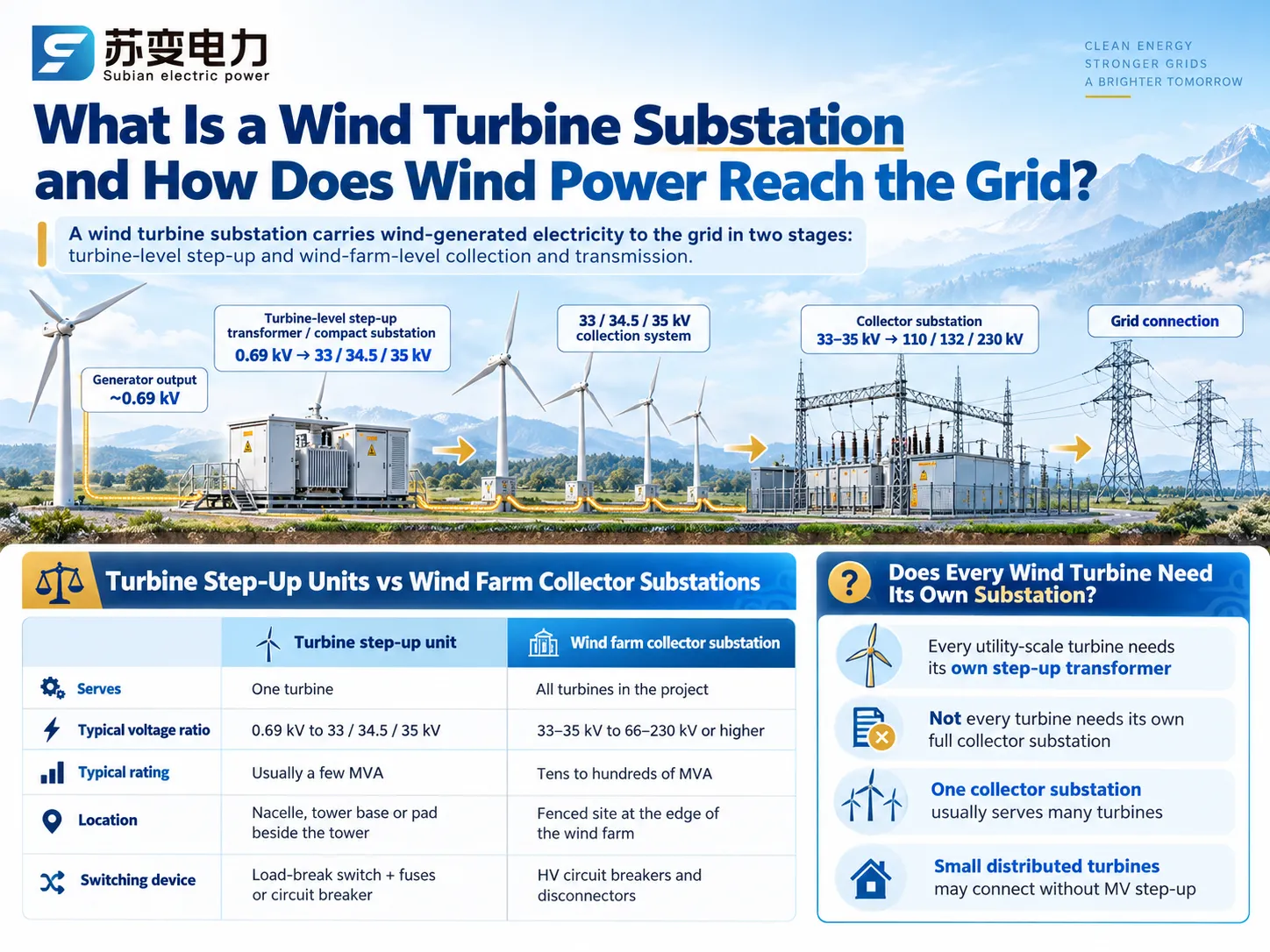
A wind turbine substation is the voltage-transformation and switching equipment that carries electricity from a wind turbine to the power grid. It usually works in two stages. First, a step-up transformer beside or inside each turbine raises the generator voltage (typically 0.69 kV) to a medium collection voltage of 33 kV, 34.5 kV or 35 kV. Second, a wind farm substation gathers the output of many turbines and raises it again to a transmission voltage such as 110 kV, 132 kV or 230 kV. Without both stages, line current and cable losses would be far too high to deliver wind power economically.
What Is a Wind Turbine Substation?
In regular speech, two different devices are referred to in a single term, which makes it easy to mix them up. The first step to correctly describe a wind project is to make the distinction.
How Electricity Travels from a Wind Turbine to the Grid
The rotor is operated by wind, followed by the generation of electricity from the generator. The electricity from the generator, in most cases, passes through a power converter, leading to the release of three-phase alternating current. This low voltage will not result in distance coverage; it is then stepped up via the wind turbine and brought through either subsurface cables or tarred overhead lines.
Turbine Step-Up Units vs Wind Farm Collector Substations
One turbine is serviced by the turbine-level unit. It can be referred to as a step up transformer of the wind turbine and usually comes as a packaged transformer with medium voltage switching and protection in one enclosure (sometimes called a combined station or a box-type station). The collector substation caters the whole wind farm. It is a fully functional high voltage station with one or more heavy transformers, circuit breakers, busbars, control building and protection relays.
| Feature | Turbine step-up unit | Wind farm collector substation |
| Serves | One turbine | All turbines in the project |
| Typical voltage ratio | 0.69 kV to 33, 34.5 or 35 kV | 33–35 kV to 66–230 kV or higher |
| Typical rating | Matched to one turbine, usually a few MVA | Tens to hundreds of MVA |
| Location | Nacelle, tower base or pad beside the tower | Fenced site at the edge of the wind farm |
| Switching device | Load-break switch with fuses, or a circuit breaker | HV circuit breakers and disconnectors |
| Main standards | IEC/IEEE 60076-16, IEC 62271-202 | IEC 60076 series, IEC 62271 series, IEC 61936-1 |
Does Every Wind Turbine Need Its Own Substation?
Each grid-connected utility-scale turbine requires a transformer of its own. However, it does not require a complete substation. The turbine-specific device is considered a transformer having local switching instead of a full substation with bus protection and control. A collector station is normally connected to multiple turbines. Distributed turbines connected to a local low-voltage line are an exception to the rule; they can be connected without any transformation to the medium voltage.
How a Wind Farm Electrical System Works
A simplified wind farm substation diagram, drawn as a single-line diagram for a typical onshore project, follows this path:
- Wind turbine generator and converter: three-phase AC voltage, normally 0.69 kV
Transformers for turbine boosting: 0.69 kV to 33, 34.5 or 35 kV
Medium voltage collection power lines: several installations in series in every cable
Substation for collecting the power: MV feeder breakers and the main transformer (34.5/230 kV or 33/132 kV)
Transmission circuit and the point of connection to the utility grid.These voltage levels are representative; actual numbers are dependent on the turbine design, transmission voltage at proximity to the place of installation and grid standards.
Wind Turbine Generator and Converter Output
Various turbines used in today’s world are termed variable-speed turbines. The electrical current from the generator must be converted to DC, which takes place within the turbine. After that, this electrical current is again changed to AC having the frequency of grid voltage in full-converter turbines. The ultimate result is AC at the terminals of the turbine, but the type of electrical current supplied by the turbine affects the performance of different equipment located downstream from this turbine.
Turbine-Level Step-Up Transformers
The transformer used in the wind turbine increases the terminal voltage to the collection level and its rating should be able to accommodate the total apparent power of the turbine as opposed to just its real power output. A turbine with a capacity of 4 MW and a power factor of 0.95 produces 4.2 MVA, thus the transformer should be rated higher than its MW capacity with allowance for reactive power and heating due to harmonics.
Medium-Voltage Collection Feeders
The wind farm collection system links turbines together. NREL’s study of a large wind power plant describes feeder circuits, underground cables or overhead lines, that tie the turbines to a 34.5 kV bus feeding the plant’s substation transformer (NREL, Equivalencing the Collector System of a Large Wind Power Plant). Turbines are usually connected in strings, with cable cross-sections increasing toward the substation as the accumulated current grows.
Collector Substation and Grid Connection
The feeder connects to its respective circuit breaker inside the collector substation. The collector voltage is then elevated to the transmission voltage by the main transformer. Typical submission announcements in North America have the collector voltage at 34.5 kV with a main transformer of the ratio 230/34.5 kV while in the IEC area the projects have a collector amounting to 33 kV with a main transformer with a ratio of either 132/33 kV or 110/35 kV. Additional equipment at the installation consists of revenue metering system, controller and utility interface.
Wind Turbine Step-Up Transformer Location and Design
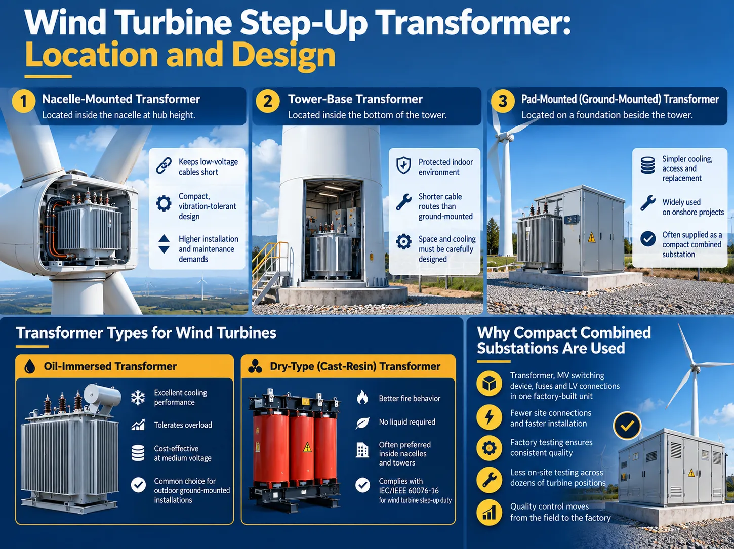
Where the turbine transformer sits, and how it is insulated and cooled, shapes cable runs, maintenance access and the type of enclosure the project needs.
Nacelle, Tower-Base and Pad-Mounted Arrangements
There are three standard locations. A nacelle transformer is located at the top of the turbine rotor, which keeps low voltage cables short. The nacelle transformer, however, requires an efficient and compact design for use in operation due to the vibration it undergoes. A transformer is found located within the base of the tower. A pad transformer is located on a pad outside of the tower base, which helps maintain its cooling as well as makes service of the transformer easy.
Oil-Immersed vs Dry-Type Transformers
In a ground-mounted installation, transformers that are liquid-immersed are very popular because they have good cooling mechanism, can withstand overloads, and are reasonably priced when dealing with normal power voltage levels. But when it comes indoors, dry-type or cast-resin types of transformers are used as they score high on fire safety issues along with being liquid-free. IEC/IEEE standard 60076-16 deals with both types of transformers for use in wind turbine applications.
Why Compact Combined Substations Are Used
The combination substation has combined the transformer, MV switching device(s), fuse and the LV connections in a single factory-made lock unit. Fewer connections required in field translates to quicker assembly and reduced testing during installations. Since it is supplied in a tested form, the quality of the installation will be significantly increased.
The reason behind 33 kV, 34.5 kV and 35 kV in Wind Farms
A Detailed Illustration: 690V against 35K
The three-phase current is represented as I=P/(√3*V*PF). For instance, lets consider a wind turbine capable of delivering P=4 MW with a power factor of 0.95.
When operating at 690 V, I=(4,000,000/(√3*690*0.95))=3,523 A
When operating at 33 kV, I=73.7 A
When operating at 34.5 kV, I=70.5 A
When operating at 35 kV, I=69.5 A
When the voltage changes from 690 V to 35 kV, the current reduces by an approximate ratio of 51. There is a constant relationship between the resistive losses to the current squared, which means that I²R losses would reduce by about 2,500 times in actual events. After all, the reductions may show as smaller cables, longer possible feeder runs or reduced voltage drops than from the same cables but lower losses.
Feeder current and voltage drop
The same formula can be applied for the entire feeder; for example, six turbines of 4 MW each (24 MW) will use a circuit of 34.5 kV at approximately 423 A on the substation side of the line, which is similar to what a medium-voltage cable can serve. When ranging power at 690 V one would have to face thousands of amperes. Each section of the feeder should be sized according to its power and voltage drop calculations should be made to fit requirements of the turbine manufacturer.
33 kV vs 34.5 kV vs 35 kV: What Buyers Must Check
| Nominal collection voltage | Where it is common | Typical equipment voltage class | Frequency |
| 33 kV | IEC markets: UK, India, Middle East, Africa, Australia | 36 kV equipment | 50 Hz (mostly) |
| 34.5 kV | North America | 38 kV class equipment | 60 Hz |
| 35 kV | China and projects built to Chinese practice | 40.5 kV equipment | 50 Hz |
These terms are not interchangeable; a transformer designed for 35 kV does not mean that it can be used for the 33 kV network with the same reliability, and a 50 Hz transformer may not necessarily operate at 60 Hz rating. The acceptable voltage, maximum voltage for the equipment being installed, number of tap positions, insulation rating and frequency must be clearly stated according to the single line diagram of the project. Buyers sourcing a 33kV wind farm substation, a 34.5kV wind farm transformer or a 35kV wind power substation should state all of these explicitly in the enquiry.
Main Components of a Wind Turbine Substation
The equipment list depends on which stage you are looking at. Not every component in the table below is installed inside a compact turbine unit.
| Component | Turbine step-up unit | Collector substation |
| Step-up transformer | One, matched to the turbine | One or more main power transformers, often with on-load tap changers |
| MV switching | Load-break switch with fuses, or a circuit breaker | Feeder circuit breakers in MV switchgear |
| HV switching | Not present | HV breakers, disconnectors, earthing switches |
| Instrument transformers | Limited or none | CTs and VTs for protection, control and revenue metering |
| Surge arresters | MV side, as specified | HV and MV sides |
| Earthing | Local earth connected to the turbine earthing system | Substation earth grid |
| Monitoring | Oil level, temperature, door and switch status | SCADA, protection relays, power quality meters |
The MV feeder breakers installed in collector substations mostly use vacuum circuit breakers, while the main transformer is safeguarded by differential and overcurrent relays fed by the current transformers positioned on both ends.
Wind Farm Substation Protection and Grid Requirements
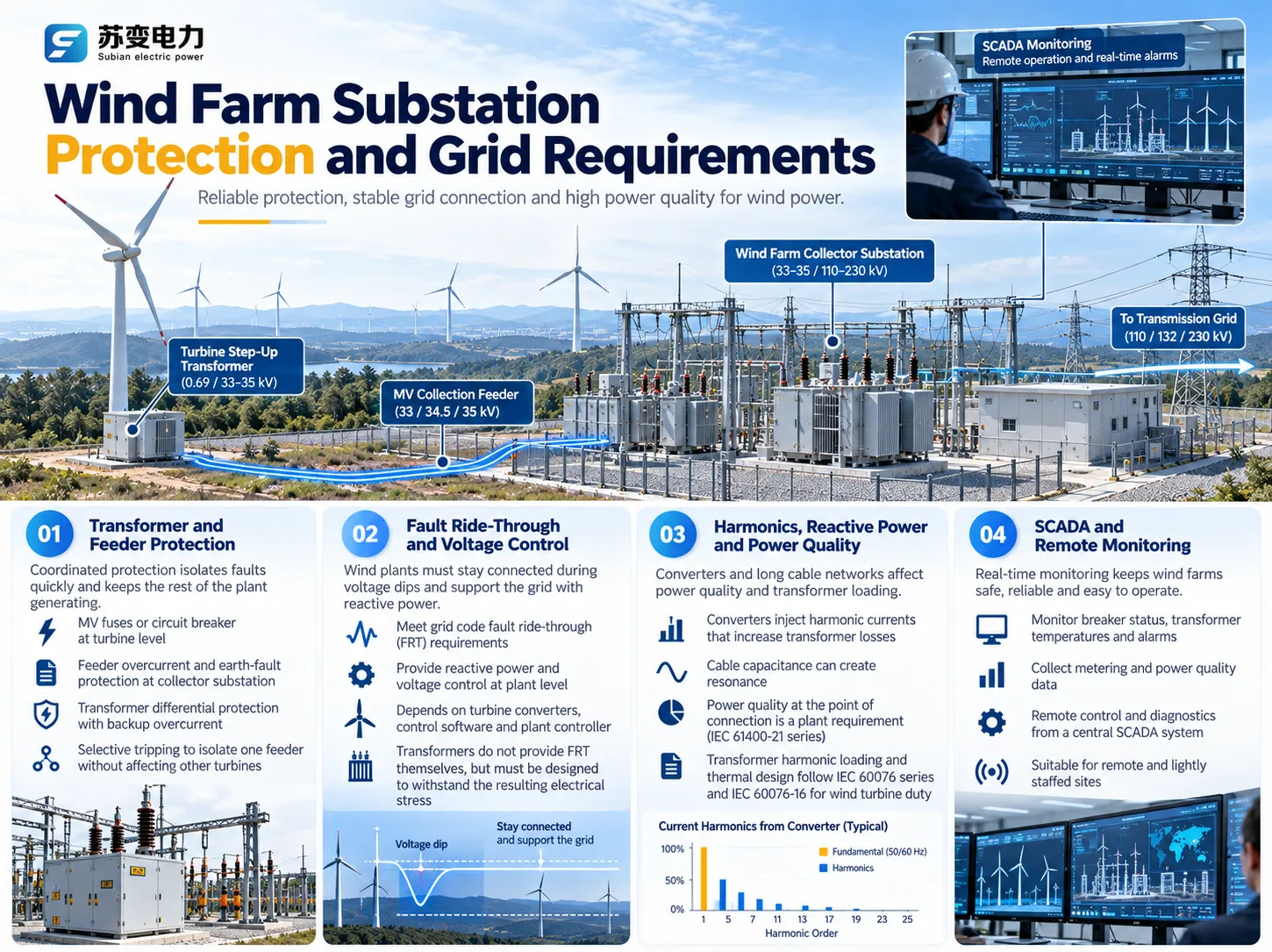
Protection keeps a single fault from taking the whole plant offline, while grid codes decide how the plant must behave when the network is disturbed. The two are related but handled by different equipment.
Transformer and Feeder Protection
At the level of turbines, either the MV fuses or circuit-breakers serve to clear any transformer failures and to separate the turbine from the feeder. The collector substation is equipped with overcurrent protection and earth faults for each feeder. The main transformer is wired with diff protection and backup overcurrent protection.. It is important to coordinate the settings, so that cable fault operating one string only causes feeder tripping and allows to keep the rest of the power plant working.
Fault Ride-Through and Voltage Control
Grid codes require wind farms to stay on grid during voltage dips and to provide voltage support through reactive power. It is an ability which should exist at the level of the whole plant and does not depend on the transformer. Instead, it is the function of the turbine converters, their software and the plant controller. Although transformer is not able to provide fault ride through on its own, its impedance and tap setting range should be suitable for such an application.
Harmonics, Reactive Power and Power Quality
Converters produce harmonic currents causing losses in transformer coils while long cables contribute capacitance which may cause the resonances. It is necessary to separate these two issues. The power quality at the point of connection is an issue of the plant which is defined according to IEC 61400-21 series. The issue of harmonic loading and thermal design of transformers is mainly the issue of equipment and is stated in IEC 60076 series and wind-specific part 16.
SCADA and Remote Monitoring
Wind farms are usually located in remote areas and are not staffed. Therefore, the protection of transformers, their temperatures, alerts and metering data are transmitted to the SCADA system, which allows operators to monitor the wind farm from any central place.
IEC Standards for Wind Turbine Substations
- IEC 60076 series: the standard lay down the basis such as rating, temperature rise, insulation, and tests. This standard is relevant to the main transformers of the collector substation.
IEC/IEEE 60076-16:2018: these are used in the wind turbine step-up applications; they can be either dry-type or liquid-immersed, with a highest voltage for equipment up to 72.5 kV. This standard applies to the transformer that connects a turbine to the collection system, but not to the transformer connecting the whole plant to the grid.
IEC 62271-202:2022:AC prefabricated substations above 1 kV and up to 52 kV, including high-voltage/low-voltage step-up and step-down designs. This is valid for compact turbine units, but the compliance with it must be demonstrated through design and type testing, and not through assumption.
IEC 61400-21-1:2019: measurement and assessment of electrical characteristics of individual grid-connected wind turbines, including power quality and ride-through tests.
IEC 61400-21-2:2023: the same for whole wind power plants, including the power plant controller. It expressly leaves the tests on components of switchgear, cables, and transformers to their own IEC standards.Request routine test results on each unit for procurement (transformation ratio, resistance, losses, impedance, and dielectric tests of transformers) plus type test results that correspond with the design and rating offered. Type testing on different voltage classes or ratings does not serve as validation for your unit.
Onshore vs Offshore Wind Substations
Onshore Compact Step-Up Units
The step-up units used for onshore projects are fixed to the ground or mounted on structures and feed energy to a stationary collector substation. Access and maintenance are easy for onshore projects.
Offshore Collection and Export Systems
When it comes to offshore projects, the step-up transformer is in the turbine, from which array cables connect each of the turbines to an offshore substation platform, then the energy is sent to the shore via high-voltage export cables. Offshore projects are increasingly utilizing 66 kV array systems and may utilize HVDC technology in very remote areas of the sea.
Environmental and Maintenance Requirements
Offshore designs call for extreme pressure, as they must deal with salt spray, humidity, and accessibility issues. The requirements for onshore units are not as challenging, however since they still deal with conditions like desert heat, extreme cold, dusty conditions, and high altitudes.
How to Select a Wind Turbine Substation
Transformer Capacity and Voltage Ratio
Select the size of turbine transformers based on the maximum apparent and reactive power generated by the turbines. It is important to consider the effect of harmonics emanating from the converter during the selection process. Finally, check that the low voltage level corresponds with the terminal voltage and the high voltage level meets the requirements of the gathering system.
Collection Network and Switchgear Ratings
Switchgear should be compatible with the highest rated voltage expected on the system, with some capability to withstand standard short-circuit levels and the earthing system. The decision between load-break switches with fuses and circuit breakers for the turbine units should be made early, as it influences protection coordination throughout the feeder.
RFQ Checklist for EPC Contractors
| Item | What to specify |
| Turbine data | Rated MW, maximum MVA, terminal voltage, converter type |
| Collection system | Nominal voltage (33, 34.5 or 35 kV), highest voltage for equipment, frequency |
| Network data | Short-circuit level, earthing method, feeder topology |
| Transformer | Rated power, vector group, impedance, tap range, cooling, loss targets |
| Switching and protection | Load-break switch and fuse, or circuit breaker; relay requirements |
| Environment | Ambient range, altitude, pollution level, corrosion category, enclosure rating |
| Standards and tests | Applicable IEC or IEEE standards, type test evidence, routine tests, witness tests |
| Documentation and supply | Drawings, single-line diagram, manuals, spares, delivery terms |
Wind Power Combined Substations from Subian Electric
Subian Electric manufactures equipment for the turbine-level stage described above. The ZGS-35/0.8 Wind Power Combined Substation raises 0.6–0.69 kV turbine output to 35 kV for the collection network. It integrates the transformer, a high-voltage load-break switch and fuses in a sealed enclosure, with transformer insulating liquid providing insulation and cooling. Capacity, voltage ratio, protection arrangement and enclosure are configured to each project’s single-line diagram and confirmed in the quotation drawings.
For the collector substation and wider network, Subian also supplies the ZN85-40.5 indoor vacuum circuit breaker for 40.5 kV switchgear, oil-immersed power transformers and solutions for 33 kV substations. The full range of renewable step-up equipment is listed under New Energy Box Change.
For a broader view of transformer duty in renewable plants, see Subian’s articles on the role of transformers in new energy power systems and transformer adaptability in the new energy field.
Frequently Asked Questions
What is a wind turbine substation?
The equipment that connects a wind turbine to the electric network is comprised of the transformer and switching equipment units. In the majority of projects it usually involves step-up transformers on every turbine and a collector substation in aggregate.
How does a wind turbine power station work?
Every turbine takes the wind energy and turns it into rotation and consequently electricity. The transformer at every turbine increases the voltage, cables help collect the energy from different turbines, and at the final substation the voltage is again raised before being transferred to the transmission grid.
Is wind turbine electricity AC or DC?
Electricity from large turbines is alternating current (AC). Several modern turbines at plants are capable of converting the output of their generators to direct current (DC) and then converting the voltage to alternating current (AC) at grid frequency. However, energy is finally collected at the turbine terminals, but the step-up transformer is working with alternating current.
Is a wind turbine enough to power a house?
A utility-scale turbine produces far more than one house needs. According to the DOE’s Land-Based Wind Market Report: 2024 Edition, newly installed U.S. turbines averaged 3.4 MW in 2023, which the DOE says is enough to power over 1,000 U.S. households. A single home would only use a small distributed turbine, sized to the household’s consumption and the local wind resource.
Why are farmers against wind turbines?
Opinions vary. Concerns raised by some landowners and neighbors include roads and turbine pads crossing fields, effects on how equipment moves around the farm, noise and visual impact. Many farmers host turbines willingly: University of Missouri Extension notes that crops can usually continue around turbines and that lease payments often far exceed cash rental rates for farmland.
Does every wind turbine need a transformer?
Every utility-scale turbine connected to a medium-voltage collection network needs a step-up transformer, located in the nacelle, in the tower base or on a pad beside the tower.
Why do wind farms use 33 kV or 34.5 kV collection systems?
Medium voltage cuts current by a factor of about 50 compared with 690 V, which keeps cables, losses and voltage drop manageable. The exact level follows regional practice: 33 kV in many IEC markets, 34.5 kV in North America and 35 kV in China.
What IEC standards apply to wind power substations?
Turbine step-up transformers are covered by IEC/IEEE 60076-16, prefabricated substations up to 52kV by IEC 62271-202, the IEC 60076 series is responsible for power transformers and the conductance of wind turbines and plants is found in IEC 61400-21 – 1 and 61400 -21 -2.
References
- U.S. Department of Energy: Explore a Wind Turbine (Text Version)
- U.S. Department of Energy: Land-Based Wind Market Report, 2024 Edition
- NREL: Equivalencing the Collector System of a Large Wind Power Plant
- IEC/IEEE 60076-16:2018 Power transformers, Part 16: Transformers for wind turbine applications
- IEC 62271-202:2022 AC prefabricated substations above 1 kV and up to 52 kV
- IEC 61400-21-1:2019 Electrical characteristics of wind turbines
- IEC 61400-21-2:2023 Electrical characteristics of wind power plants
- University of Missouri Extension: Wind energy agreements for landowners
Conclusion
A device commonly known as wind turbine substation can be defined as a dual-phase facility consisting of step-up devices for every wind turbine. The substation consists of two components; the first stage is responsible for transforming the voltage level from approximately 0.69 kV to the level of either 33 kV, 34.5 kV, or 35 kV and the second component is responsible for sending the collected generated power to transmission level. If both components are considered as one, equipment specification will turn out to be wrong. The requirement that ‘33 kV, 34.5 kV and 35 kV are interchangeable’ is also wrong. Get the right voltage level needed, frequency used, and the apparent-power rating, arrange the protections, and specify the test results in accordance with the RFQ.
Summary of the most important facts:
– Own transformator is required for each turbine as one collector station is responsible for the entire wind farm;
– The current decreases approximately 51 times when transformed from 690 V to 35 kV;
– Specify the voltage as 33 kV, 34.5 kV or 35 kV in the RFQ, without competition with other types;
– Fault ride-through is guaranteed by converters and controls and is not presented by transformer only;
– Make sure that type tests correspond with design proposals, while routine tests are also required for each unit.
If you are planning a wind project and need turbine-level step-up equipment, contact Subian Electric with your turbine data, collection voltage and single-line diagram. Our engineering team will confirm the configuration and return drawings and a quotation for the ZGS-35/0.8 Wind Power Combined Substation.