


Wenn man die Stromrechnung und die Produktionszuverlässigkeitsaufzeichnungen betrachtet, ist der Anlageningenieur in einer Situation gefangen, in der eine Anlage rund um die Uhr betrieben wird, einen Energiepeak von 1,8 MW zieht und in diesem Geschäftsjahr bisher drei Produktionsausfälle (aufgrund von Unterspannungsabschaltungen) erlitten hat. Ein Versorgungsunternehmen schlägt eine dedizierte Versorgung eines 33 kV-Netzes vor, was eine Transformatorinstallation am Eingang erfordert. Einer der Vertriebsmitarbeiter hat behauptet, dass ein 2.000 kVA Transformator für die Bedürfnisse der Anlage geeignet sein sollte. Der Ingenieur ist sich bewusst, dass “sollte” nicht bedeutet, einen Transformator korrekt zu dimensionieren, und ein falscher kVA-Verbrauch zu langfristigen Kosten führen würde, während ein falsches Spannungsverhältnis jeden Vorteil der vorgeschlagenen Transformatorinstallation neutralisieren würde. Daher benötigt sie ein System zur Auswahl eines korrekten ölgefüllten Transformators.
Dieser Einkaufsführer dient als das erforderliche System. Er führt durch eine Reihe von acht Entscheidungen, die den Auswahlprozess für Transformatoren definieren, wie z.B. kVA-Auswahl, Bestimmung des Spannungsverhältnisses, Parameter und Eigenschaften eines Transformators, Abgriffbereich, Verlustniveau und viele andere mit allen entsprechenden Zahlen und Standards.
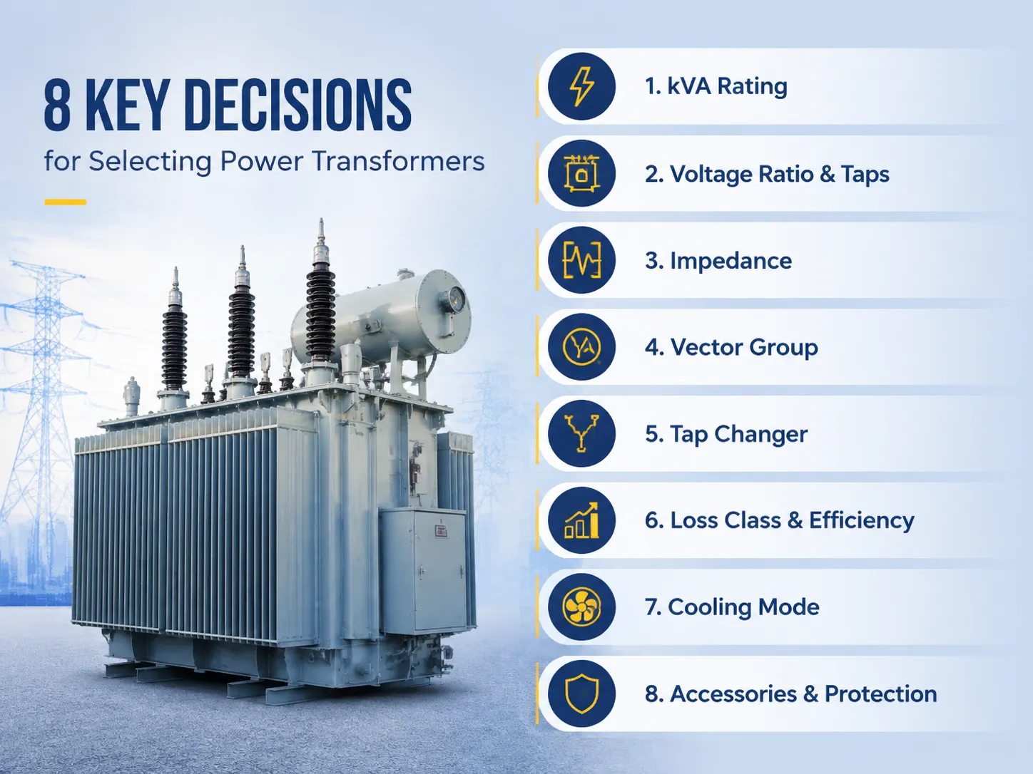
Kurz gesagt, bei der Auswahl eines ölgefüllten Transformators kommen acht wichtige Variablen ins Spiel: (1) Die kVA-Größe sollte die maximalen Spitzen plus eine Marge von 15–25 Prozent berücksichtigen; (2) Spannungsverhältnisse müssen mit der Linie des Dienstanbieters und des Planers abgestimmt sein; (3) Die Impedanz liegt häufig im Bereich von 4,5–8 Prozent, basierend auf Klasse und Koordination des Fehlerpegels; (4) Vektorgruppen müssen mit der Erdung des Systems und dem Grad der Phase synchronisiert werden; (5) Der Abgriffbereich ist auf ±2 mal 2,5 Prozent außerhalb des Stromkreises für stabile Netze oder ±8 mal 1,25 Prozent im Stromkreis für schwache Netze eingestellt; (6) Die Verlustklasse des Transformators wird gemäß GB 20052 oder EU-Ecodesign festgelegt, indem die Verluste kapitalisiert werden; (7) Die Kühlung sollte je nach Lastfaktor zwischen ONAN oder ONAF gewählt werden; und (8) Die optionale Ausrüstung umfasst Buchholz-Relais, PRD, Temperaturüberwachung und Vibrothermometer.
Inhaltsverzeichnis
- Entscheidung 1: Dimensionierung der kVA-Bewertung
- Entscheidung 2: Spannungsverhältnis und Abgriffe
- Entscheidung 3: Impedanz
- Entscheidung 4: Vektorguppe
- Entscheidung 5: Wahl des Abgriffwechslers
- Entscheidung 6: Verlustklasse und Effizienz
- Entscheidung 7: Kühlmodus
- Entscheidung 8: Zubehör und Schutz
- Die Auswahlmethode in sechs Schritten
- Marken und Preisrichtlinien
- Häufig gestellte Fragen
- Referenzen
- Fazit
Entscheidung 1: Dimensionierung der kVA-Bewertung
Die Entscheidung, die alle anderen leitet, ist die Dimensionierung, da jede spätere Entscheidung im Kontext eines Bewertungsrahmens erfolgt. Der richtige Weg:
- Bestimmen oder bewerten Sie die Spitzenlast. Verwenden Sie einjährige Messdaten (z.B. Laststudie) oder, falls der Standort neu ist, bestimmen Sie die angeschlossene Last und wenden Sie einen Diversitätsfaktor an (475 für kommerzielle und 0,5-0,8 für industrielle Last).
- Umrechnen in kVA. kVA = kW/Leistungsfaktor. Bei einem Leistungsfaktor von 0,9 wird die Spitzenlast von 1,8 MW in 2.000 kVA umgerechnet; bei einem Leistungsfaktor von 0,8 – in 2.250 kVA.
- Verwenden Sie immer den tatsächlichen oder vorhergesagten Leistungsfaktor, nicht 1,0.
- Führen Sie die Wachstumsreserve ein. Fügen Sie 15-25% für das Lastwachstum über den Planungszeitraum von 5-10 Jahren hinzu. Zum Beispiel wird aus 2.000 kVA 2.300-2.500 kVA.
- Runden Sie auf die Standardbewertung. Standard-kVA-Inkremente in diesem Bereich sind 1600/2000/2500 und 3150.
| Berechnete kVA (Laststudie) | Standardbewertung zur Bestellung | Typische Anwendung |
|---|---|---|
| Bis zu 400 kVA | 400 / 500 kVA | Kleine Gewerbe, Dörfer |
| 400–800 kVA | 630 / 800 / 1.000 kVA | Fabriken, Einkaufszentren |
| 800–1.300 kVA | 000 / 1.250 / 1.600 kVA | Mittlere Industrie |
| 300–2.200 kVA | 000 / 2.500 kVA | Große Anlagen, Campus |
| Über 2.200 kVA | 150 kVA und mehr | Umspannwerke, Schwerindustrie |
Wählen Sie die nächstgelegene geeignete Bewertung, die den berechneten Wert übersteigt. In diesem Fall war der abgeleitete Wert in unserem Fall 2.500 kVA.
Zwei häufige Größenfehler sind kostspielig. Überdimensionierung (z.B. Verwendung eines 3.150 kVA Geräts für benötigte 2.000 kVA) verursacht unnötige Kosten durch Leerlaufverluste, die während der Lebensdauer des Geräts anfallen – der Leerlaufverlust eines 3.150 kVA Geräts (von etwa 4,4) entspricht $3100 pro Jahr bei $0,08 pro kWh. Unterdimensionierung führt zu Überlastbetrieb, führt zur Alterung von Isolatoren und verursacht Auslösungen bei Spitzenlast. Die richtige Größe wird durch die Laststudie definiert, nicht durch die runde Zahl vom Händler.
Entscheidung 2: Spannungsverhältnis und Abgriffe
Das Spannungsverhältnis muss an beiden Enden des Systems gleich sein: die Spannung vom Versorgungsunternehmen und die Spannung im Bus. Die häufigsten Paare sind unten aufgeführt:
| Einspeisespannung | Lastseitiger Bus | Typisches Gerät |
|---|---|---|
| 33 kV | 11 kV | 33/11 kV Verteilung |
| 35 kV | 10,5 kV | 35/10,5 kV Leistung |
| 22 kV | 11 kV | 22/11 kV Verteilung |
| 11 kV | 4 kV | 11/0,4 kV Pfosten- oder Bodenmontage |
| 6,6 / 6,3 kV | 4 kV | 3/0.4 kV industriell |
Der Bereich der Abgriffe wird auf der Hochspannungsseite bestimmt und kompensiert sowohl die Änderung der Spannung des Versorgers als auch den Spannungsabfall vom Transformator. Der Fall, wenn die Spannungsversorgung mit einer Genauigkeit von ±2.5% konstant ist, kann mit Abgriffen außerhalb des Stromkreises mit der Position ±2 × 2.5% durchgeführt werden. In Situationen, in denen die Versorgung schwach und/oder die Last sich ändert, sorgt ein Lastabgriffwechsler mit einer Regelung von ±8 × 1.25% für die erforderliche Kontrolle. Wirtschaftlich gesehen erhöht der OLTC die Kosten des Transformators um 15-30%, was nur dann sinnvoll ist, wenn tatsächlich Änderungen in der Spannung auftreten.
Entscheidung 3: Impedanz
Der Impedanzfaktor (Kurzschluss-Spannung, UK%) bestimmt zwei Faktoren, die miteinander in Konflikt stehen können: Spannungsregulierungsmerkmale und Kurzschlussstrom. Die geringere Beeinträchtigung ist mit einer stärkeren Regelung verbunden, führt jedoch gleichzeitig zu einem größeren Kurzschlussstrom. Andererseits wird der höhere die Impedanz, desto kleiner wird der Kurzschlussstrom sein, aber der Spannungsabfall wird größer sein. Die allgemeine Regel ist, den Transformator zu implementieren, der mit den bereits verwendeten Schutz- und Schaltgeräten kompatibel ist:
- Verteilungstransformatoren (≤1.000 kVA): 4 – 4.5% ist die Norm;
- Mittelgroße Transformatoren (1,6 – 10 MVA): 6% – 8% ist der Durchschnitt; 7.5% ist eine gängige Spezifikation;
- Schwere Transformatoren (>10 MVA): 8% – 14%, je höher die Leistung, desto höher die Impedanz.
Die falsche Impedanz kann ein Koordinationsrisiko darstellen. Wenn die gewählte Impedanz zu klein ist, wird der Transformator den Kurzschlussstrom liefern, der über die Fähigkeit des Leistungsschalters hinausgeht, diesen zu beseitigen.
Entscheidung 4: Vektorguppe
Die Definition der Vektorguppe umfasst die Wicklungskonfiguration und Phasenverschiebung des Transformators sowie seine Erdungskonfiguration und Anforderungen an den Parallelbetrieb. Zwei der häufigsten Vektorguppen, die in ölgetauchten Transformatoren verwendet werden, sind:
- Dyn11: Delta-Konfiguration auf der Hochspannungsseite und Sternkonfiguration auf der Niederspannungsseite (mit dem Neutralleiter vom Transformator). Diese Vektorgruppenauszeichnung wird normalerweise für Verteilungstransformatoren (z.B. 11/0.4 kV) verwendet, die entweder in einphasigen oder dreiphasigen Schaltungen betrieben werden.
- YNd11: Sternkonfiguration auf der Hochspannungsseite (mit dem Neutralleiter vom Transformator) und Delta-Konfiguration auf der Niederspannungsseite. Diese Vektorgruppenauszeichnung ist üblich für Leistungstransformatoren (z.B. 35/10.5 kV), die die geerdete Seite über den Neutralleiter des Transformators speisen.
Die Bedeutung der Vektorguppe wird offensichtlich, wenn zwei oder mehr Einheiten parallel geschaltet werden. Zwei Transformatoren, die an denselben Bus angeschlossen sind, müssen den gleichen Phasenverschiebungswinkel sowie übereinstimmende Impedanzen von ±7.5% haben. Wenn die Vektorguppen unterschiedlich sind, entstehen zirkulierende Ströme, die zu einer Überhitzung der Transformatoren führen, was ein kostspieliges Problem darstellt, das durch Überprüfung des Typenschilds vermieden werden kann.
Entscheidung 5: Wahl des Abgriffwechslers
Laut Experten ist der Abgriffwechselmechanismus das einzige bewegliche Teil des Transformators. Die Entscheidung zur Auswahl der Abgriffe hängt mit der Zuverlässigkeit zusammen.
| Typ | Typischer Bereich | Betrieb | Kostenimpact | Wartung |
|---|---|---|---|---|
| Off-Kreis (DETC) | ±2 × 2.5% | Nur spannungsfrei | Basislinie | Keine über die Inspektion hinaus |
| Unter Last (OLTC), ölgetauchter Widerstand | ±8 × 1.25% oder ±6 × 1.67% | Unter Last | +15–30% | 000–100.000 Betriebszyklen |
| OLTC, Vakuumtyp | ±8 × 1.25% | Unter Last | +20–35% | 000–200.000 Betriebszyklen |
Wenn die Stromversorgung stabil und die Last konstant ist, können Abgriffe im Leerlauf verwendet werden. Wenn eine Regelung unter Last erforderlich ist, muss die Stromversorgung um mehr als ±2.5% variieren, falls die Last instabil ist oder der Prozess aufgrund von Unterspannungsereignissen nicht funktionieren kann. Der Preisunterschied ($6.000-12.000) für eine 10 MVA Einheit erscheint im Vergleich zu den Verlusten, die durch längere Unterspannung verursacht werden, unbedeutend.
Entscheidung 6: Verlustklasse und Effizienz
Die meisten Lebenszykluskosten werden in der Verlustkategorie bewertet. Zwei häufig verwendete Verlustmessungen sind Leerlaufverlust (P0, der den ganzen Tag anhält) und Lastverlust (Pk, abhängig vom Quadrat des Lastfaktors). Befolgen Sie die Empfehlungen:
- Halten Sie sich an die geltenden Standards: Überprüfen Sie GB 20052-2020 in China, die EU-Ecodesign-Verordnung 548/2014 in Europa und U.S. DOE 10 CFR Teil 431, da sie eine Obergrenze für Verluste haben, die sehr nützlich ist.
- Schätzen Sie den Unterschied: Jeder kW von P0 wäre wert tariff × 8.760 h × Projektlebensdauer. Jeder kW von Pk wäre wert tariff × 8.760 h × (durchschnittlicher Lastfaktor)² × Projektlebensdauer.
- Wählen Sie die Verlustklasse mit niedrigem Verlust im Falle eines hohen Lastfaktors: Mit P0-Werten von 60-70% niedriger bei Verwendung eines amorphen Kerntransformators kann sich eine Investition innerhalb von 6-12 Jahren amortisieren und weiterhin Gewinn bringen.
Einige Statistiken zu einer 1.000 kVA Einheit: Die Niedrigverlusttechnologie hat ungefähr 1.1 kW niedrigeren P0 als S11, was etwa $770/Jahr bei $0.08/kWh entspricht, $19.000, die über 25 Jahre zu zahlen sind, im Vergleich zu $3.000-$6.000, die anfänglich zu zahlen sind.
| Lastfaktor | S11 Leerlaufverlust (1.000 kVA) | Amorpher Leerlaufverlust | Jährliche Einsparung @ $0.08/kWh |
|---|---|---|---|
| 3 (leicht) | 7 kW | 6 kW | $770 |
| 6 (durchschnittlich) | 7 kW | 6 kW | $770 |
| 9 (schwer / 24/7) | 7 kW | 6 kW | $770 |
Der Leerlaufverlust bleibt unabhängig vom Lastfaktor ähnlich. Das bedeutet, dass die Einsparungen konstant bleiben. Hohe Betriebsstunden stellen sicher, dass die Investition in Premium schnell amortisiert wird.
Entscheidung 7: Kühlmodus
Beim Wechsel eines Transformators in den Kühlmodus wird die thermische Grenze und die zulässige Überlast bestimmt. Folgendes zeigt die aktuellen Standards und deren Interpretationen an:
- ONAN: Öl und Luft werden natürlich zur Kühlung des Transformators verwendet. Dies ist die grundlegendste Art der Kühlung, die einfachste, leise und ohne fehleranfällige Komponenten.
- ONAF: Ventilatoren werden zusätzlich zum Öl zur Kühlung hinzugefügt. Dies erhöht die Leistung um 20 bis 30 Prozent mit dem Einsatz der Ventilatoren, was nur für Überlastungen oder intermittierende Lasten geeignet ist.
- OFAF/ODAF: Die erzwungene Kühlmethode mit dem Einsatz von Ventilatoren für die größten Transformatoren – wenn die Wärme nicht mit der natürlichen Konvektionskühlung abgeführt werden kann.
Wenn Ihr Lastfaktor kleiner als etwa 0,8 ist und Sie nur wenige Spitzen haben – wählen Sie ONAN. Wenn Sie häufig kurzfristige Überlastungen erwarten – wählen Sie ONAN/ONAF: In diesem Fall könnte Ihr 1.000 kVA Verteilungstransformator mit Hilfe von Lüftern 1.250 kVA erreichen. Stellen Sie sicher, dass die Überlastkarte den Anforderungen von IEC 60076-7 entspricht.
| Kühlmodus | Basisbewertung | Kurzfristige Überlastreserve | Hardware |
|---|---|---|---|
| ONAN | 100% (Typenschild) | Typischerweise 120–130% für 1–2 h gemäß IEC 60076-7 | Nur Radiatoren |
| ONAN/ONAF | 100% mit ausgeschalteten Lüftern | +20–30% mit eingeschalteten Lüftern | Radiatoren + Lüfter |
| OFAF / ODAF | Zwangskühlungsbewertung | Begrenzung durch heiße Stelle der Wicklung | Pumpen + Lüfter |
Entscheidung 8: Zubehör und Schutz
Die Liste der Zubehörteile ist kurz, sie ist bei der Wartung zwingend erforderlich und häufig der entscheidende Punkt, um zwischen einem Vorfall und einer Katastrophe zu unterscheiden:
- Buchholz (Gas) Relais: Langsame Gasalarmierung und schnelle Ölsurge-Abschaltung für Geräte vom Typ Konservator mit mehr als ~1 MVA. Verdrahten Sie es und führen Sie die Tests durch.
- Druckentlastungsgerät: Entlastet den Tank von internem Druck; dimensionieren Sie es entsprechend dem Gerät.
- Öl- und Wicklungstemperaturanzeigen: Mit den Alarmen und Abschaltungen, die gemäß dem 65K-Anstiegsbudget eingestellt sind.
- Ölstandsanzeiger: Niedriger Stand lässt Wicklungen öffnen; überprüfen Sie es während der vierteljährlichen Inspektion.
- Silikagel-Atmer: Entfeuchtet die Luft, die in den Konservator eintritt; wechseln Sie das Silikagel, wenn es bereits rosa ist.
- Ölauffang: Bund oder Grube, die das gesamte Volumen des Öls aufnehmen kann, wie von IEC 61936-1 und lokalen Vorschriften vorgeschrieben.
Keines dieser Teile kostet viel im Vergleich zum Gerät, und zusammen verwandeln sie den ölgetauchten Transformator von einer Brandgefahr in ein verwaltetes Asset. Budgetieren Sie 1–3% des Einheitspreises für das gesamte Schutzset.
Die Auswahlmethode in sechs Schritten
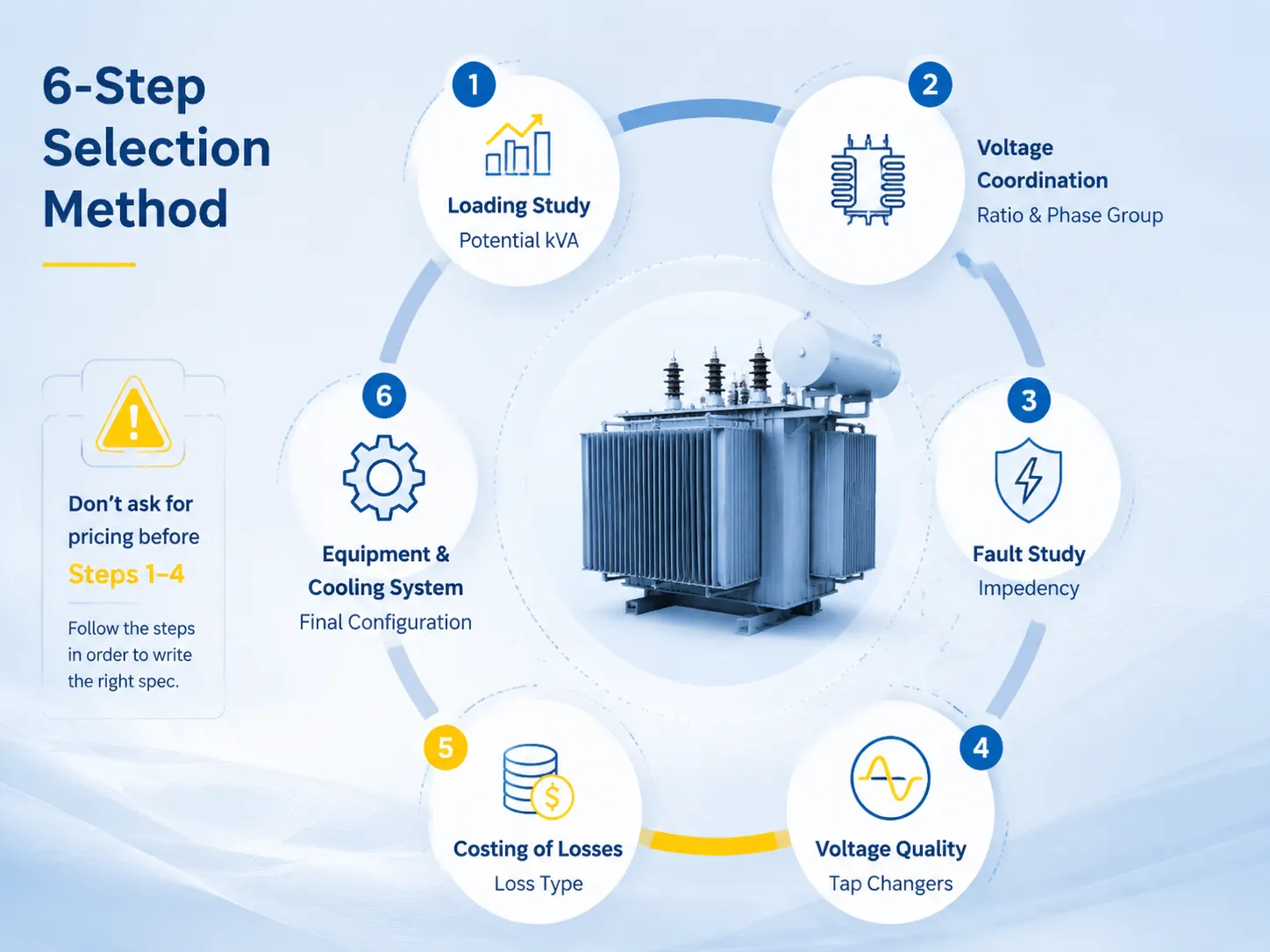
- Laststudie: maximale kW, Leistungsfaktor, Lastfaktor, Wachstumsplan → potenzielle kVA.
- Spannungskoordination: Versorgungs- spannung, Busspannung, Erdung, Interconnectionsanforderungen → Verhältnis und Phasengruppe.
- Fehlerstudie: Kurzschlussleistung, Schaltanlagenbewertungen → Unzulänglichkeit.
- Entscheidung zur Spannungsqualität: Versorgungsstabilität und Lastvolatilität → Typ und Bereich der Abgrenzungswandler.
- Kosten der Verluste: Tarif und Lastfaktor → Art der Verluste (S11, S13, amorphe oder regulierte Markenzeichenverluste).
- Ausrüstung und Kühlsystem: Überlastplan, Sicherheit, Eindämmungsstrategie → endgültige Konfiguration.
Stellen Sie sicher, dass Sie all diese Schritte in der richtigen Reihenfolge ausführen, und Sie werden die Spezifikation schreiben. Die Hauptabkürzung — die Anfrage nach Preisen, bevor Sie tatsächlich die Schritte 1-4 anwenden — ist der Grund für viele unglückliche Käufe, da sie allen Einfluss auf diejenigen gibt, die zuerst auf das Schreiben antworten.
Marken und Preisrichtlinien
| Marke | Herkunft | 000 kVA | 500 kVA | 10 MVA |
|---|---|---|---|---|
| Hitachi Energie | Japan/Weltweit | $22.000–$34.000 | $38.000–$55.000 | $55.000–$82.000 |
| ABB | Schweiz/Weltweit | $20.000–$31.000 | $35.000–$52.000 | $52.000–$78.000 |
| Siemens Energie | Deutschland/Weltweit | $21.000–$32.000 | $36.000–$53.000 | $50.000–$75.000 |
| Schneider Electric | Frankreich/Weltweit | $19.000–$29.000 | $33.000–$48.000 | $48.000–$72.000 |
| Jiangsu Subian Electric Power | China | $14.000–$22.000 | $22.000–$34.000 | $28.000–$48.000 |
Globale Unternehmen bieten Lösungen mit spezialisierter Ingenieurtechnik, Erfahrung in der Feldprüfung und globalen Servicefähigkeiten, während Offshore-Produzenten IEC-konforme Produkte zu sehr wettbewerbsfähigen Preisen anbieten. Nach der Risikobewertung ist die Wartung der Ausgaben für wichtige Artikel zuverlässig, während die kostensparende Alternative für die Massenproduktion in der Regel machbar ist.
Jiangsu Subian Electric Co. Ltd ist ein chinesischer Hersteller von Ölpumpen, der Verteilungstransformatoren und Leistungstransformatoren mit Spannungsnennwerten von 35–110 kV gemäß den IEC 60076-Spezifikationen produziert. Die technischen Berichte jedes Geräts, die Einhaltung der GB 20052-Normen und die Fähigkeit zur Regelung der Leerlaufspannung sind Teil der Erfahrung, die das Unternehmen erworben hat. Produktdetails und Zertifikate sind unter subian-electric.com.
Häufig gestellte Fragen
Wie berechne ich die benötigte kVA?
kVA = maximale kW / Leistungsfaktor, plus 15 bis 25 Prozent Wachstumsreserve, auf eine Standardbewertung gerundet. Zum Beispiel entsprechen 1,8 MW bei 90 Prozent Leistungsfaktor 2.000 kVA; mit 25 Prozent Wachstumsreserve entspricht das 2.500 kVA. Wann immer möglich, verwenden Sie gemessene Spitzenwerte; für neue Standorte addieren Sie die angeschlossene Last und verwenden einen Diversitätsfaktor, der je nach Art der Einrichtung von 0,3 bis 0,8 variiert.
Welches Spannungsverhältnis sollte ich wählen?
Stellen Sie sicher, dass Ihre Bus-Betriebsspannung auf der Niederspannungsseite mit den Versorgungsspannungen auf der Hochspannungsseite übereinstimmt, z.B. 33/11 kV oder 35/10,5 kV oder 22/11 kV oder 11/0,4 kV. Holen Sie sich eine schriftliche Bestätigung der Betriebsspannung von der Versorgungsunternehmen, bevor Sie die Bestellung aufgeben; beachten Sie, dass der Wechsel vom 33 kV-Spannungssystem zum 35 kV-Spannungssystem keine einfache Aufgabe ist und eine Neugestaltung erfordert.
Brauche ich einen Lastabgriff?
Dies gilt nur, wenn Ihre Spannung wirklich schwankt. Wenn das Versorgungsunternehmen innerhalb von ± 2,5 Prozent stabil bleibt und Ihre Last konstant ist, sind Abgriffe außerhalb des Stromkreises bei ± 2 von 2,5 Prozent ausreichend. Andererseits, wenn das Netz schwach ist, die Lastschwankungen recht groß sind oder Ihr Prozess in Bezug auf Unterspannung empfindlich ist, wird die zusätzliche Kosten eines OLTC von 15–30 Prozent durch eine einzige vermiedene Produktionsausfallzeit wieder hereingeholt.
Wie viel kostet der richtige Transformator?
Allgemein gesagt, laut einem Anbieter, liegen die Preise FOB $6.000 bis $16.000 für den 500 kVA Transformator, $14.000 bis $34.000 für den 1.000 kVA Transformator, $22.000 bis $55.000 für den 2.500 kVA Transformator und schließlich $28.000 bis $82.000 für 10 MVA, abhängig von Typ, Hersteller und Größe des Transformators. Transport-, Installations- und Baukosten liegen zwischen 15 und 40%, abhängig von der Lokalität.
Was ist der Unterschied zwischen Dyn11 und YNd11?
Die Standardkombination für Verteilungseinheiten, die ein- und dreiphasige Lasten mit Neutralleiter bereitstellen, ist Dyn11. Für 35/10,5 kV Leistungstransformatoren gilt die YNd11-Kombination, da die Hochspannungsseite über den Neutralleiter des Transformators geerdet ist. Die Wahl des Verbindungstyps hängt von der Erdungsanordnung und den Anforderungen für den Parallelbetrieb ab.
Referenzen
- IEC 60076-1: Leistungstransformatoren – Allgemeines — Bewertungen, Abgriffe, Impedanztoleranzen und Temperaturanstiegsregeln für die Auswahlentscheidungen in diesem Leitfaden.
- IEC 60076-5: Fähigkeit, Kurzschluss zu widerstehen — Kurzschlusskoordinationsbasis für die Impedanzauswahl.
- IEC 60076-3: Isolationsniveaus und dielektrische Tests — Impulspegel nach Spannungsgruppe, die in der Spezifikation referenziert werden.
- EU-Ecodesign-Verordnung 548/2014 (geändert 2019/1783) — Verlustbenchmarks für europäische Käufer.
- U.S. DOE Effizienzstandards für Verteilungstransformatoren — Mindesteffizienz-Baselines für US-Käufer.
- IEEE C57.12.00: Flüssigkeitsgetauchte Verteilungs- und Leistungstransformatoren — Nordamerikanische Anforderungen als Vergleich für die Auswahl.
- Offizielle Website von Jiangsu Subian Electric Power — Ölgetauchter Transformatorbereich, Effizienzklassen und Zertifizierungsdokumentation.
Fazit
Ein ölgetauchter Transformator erfordert die Eingabe von acht verschiedenen Eingabebedürfnissen, anstatt nur einer einzigen Eingabe in Bezug auf die Kosten. Wenn er richtig dimensioniert, mit anderen Komponenten abgestimmt und korrekt spezifiziert wird, wird Ihr Transformator zu einem stillen Vermögenswert für etwa 25 Jahre. Wenn diese Schritte vernachlässigt werden und in diesem Prozess Eile gezeigt wird, wird der Transformator zu einem ständigen Kopfzerbrechen. Die folgenden Punkte sind die wichtigsten, die Sie bei der Spezifizierung Ihres ölgetauchten Transformators berücksichtigen müssen:
- Beginnen Sie mit einer geeigneten Laststudie und lassen Sie einen Spielraum von 15-25%; der kVA-Größenrechner für Transformatoren ist nur ein erster Schritt, um die erforderliche kVA des Transformators herauszufinden.
- Stellen Sie sicher, dass Sie das Verhältnis, die Impedanz und die Vektorgruppeneigenschaften Ihres Transformators kennen, bevor Sie Angebote einholen.
- Sie sollten nur einen OLTC kaufen, um ein variierendes Spannungsniveau aufrechtzuerhalten; OLTC erhöht die Kosten des Transformators um 15-30%.
- Die tatsächlichen Kosten sollten für den Leistungsverlust in Transformatoren berechnet werden; in der Regel amortisiert sich ein verlustarmer Transformator über die Jahre.