


While carrying out a mining operation in Western Australia, the electrical engineer had a problem of providing the remote crushing plant with appropriate power supply. The equipment on site needed 415 V three-phase power for powering the motors of the crusher, 240 V single-phase power for the lighting and amenities, as well as a neutral point reliable enough for the ground-fault protection system. In total, three transformers – step-down, auxiliary, and grounding one – would represent the solution in terms of electrical performance, but the remote area of operation, space limitation on a skid, as well as high transportation and installation cost of separate transformers did not allow to use three-transformer solution. The solution established was using the transformer of combined design which allowed to integrate the functions of voltage transformation and auxiliary power supply. The transformers of combined design arrived in the site as a single shipment, took the time of a day for installation, and functioned flawlessly for six years. The question of how to choose the combined transformer of the required type represents the quest for multi-functional transformer capable to perform the functions which should be otherwise fulfilled separately rather than being able to understand the types of combined transformers available on the market and their applications, which has to be taken into account while making the choice.
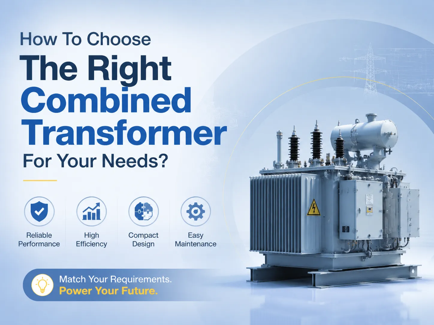
A combined transformer is one transformer that performs two or more electrical functions simultaneously that would otherwise require two transformers. The types of combined transformers most commonly used include the wye-delta grounding transformer , the dual-winding transformer , the three-winding transformer , the pad-mounted transformer .
The advantage of the use of combined transformers is in reduction of the equipment footprint which leads to simplification of the installation and reduced number of interconnections and lower cost compared to the amount of transformers. The disadvantage of the combined transformer is in the fact that if one transformer fails all its functions will be out of order and that it will be more complicated to make modifications and extensions in the combined transformer than for the separate units. The key to successful specification is that all functions of the transformer should be accurately specified, and a certain configuration chosen that would correspond to the requirements, along with type tests made by a manufacturer.
What a Combined Transformer Is — and Why It Is Specified
A combination transformer is a transformer that combines two or more electrical functions in one unit: reproduction of voltage, grounding, auxiliary power supply, protection of circuits, and metering. It is not treated like a product category with a standard set of specifications. It’s an approach to design that avoids installing three transformers, each of which has its own equipment, core, bushing, protection oh its own, and wiring. Instead the engineers can have one transformer with all non-voltage transforming functions well suited. The simplest and most popular configuration of the combined transformers used in industry in two and utility applications is a wye-delta grounding transformer with an additional secondary circuit. The wye-connected primary winding of this transformer has a neutral point for grounding the circuit depending on the grounding type. The delta-connected secondary windings ensure that three-phase auxiliary power is supplied to the station service loads e.g. for lighting purposes, and other means of ensuring control of the functioning of the electrical grid. The combination transformer works now as a grounding transformer and an auxiliary power transformer, eliminating the need for using two additional transformers.For engineers, the use of these types has the advantage of ensuring a reduction in area of the substations or pumping or compressing plant or remote unit. All of this combines to reduce foundation use and conduit needed, as well as minimize the number of safety devices and make the protection scheme easier without the major increases in total equipment costs of up to 20%–30% in contrast to the option of purchasing two transformers separately.
Other combined transformers’ configurations used other than the dual winding transformer with an integral OLTC which can be used if the primary voltage changes, being a good solution for long power lines, therefore regulating voltage automatically; the three winding transformer except having one primary and two secondary windings at different voltage levels provides feeding of two independent sets of loads through the transformer without affecting each other; the pad-mounted transformer with integral switchgear and metering is used for building the standard underground distribution stations in residential areas.For an overview of the full range of transformer types and configurations available for these and other applications, see the product catalogue at Subian Electric, which includes combined transformers, grounding transformers, distribution transformers, and specialty power transformers.
How to Specify the Voltage, the kVA, and the Grounding Requirements for a Combined Transformer
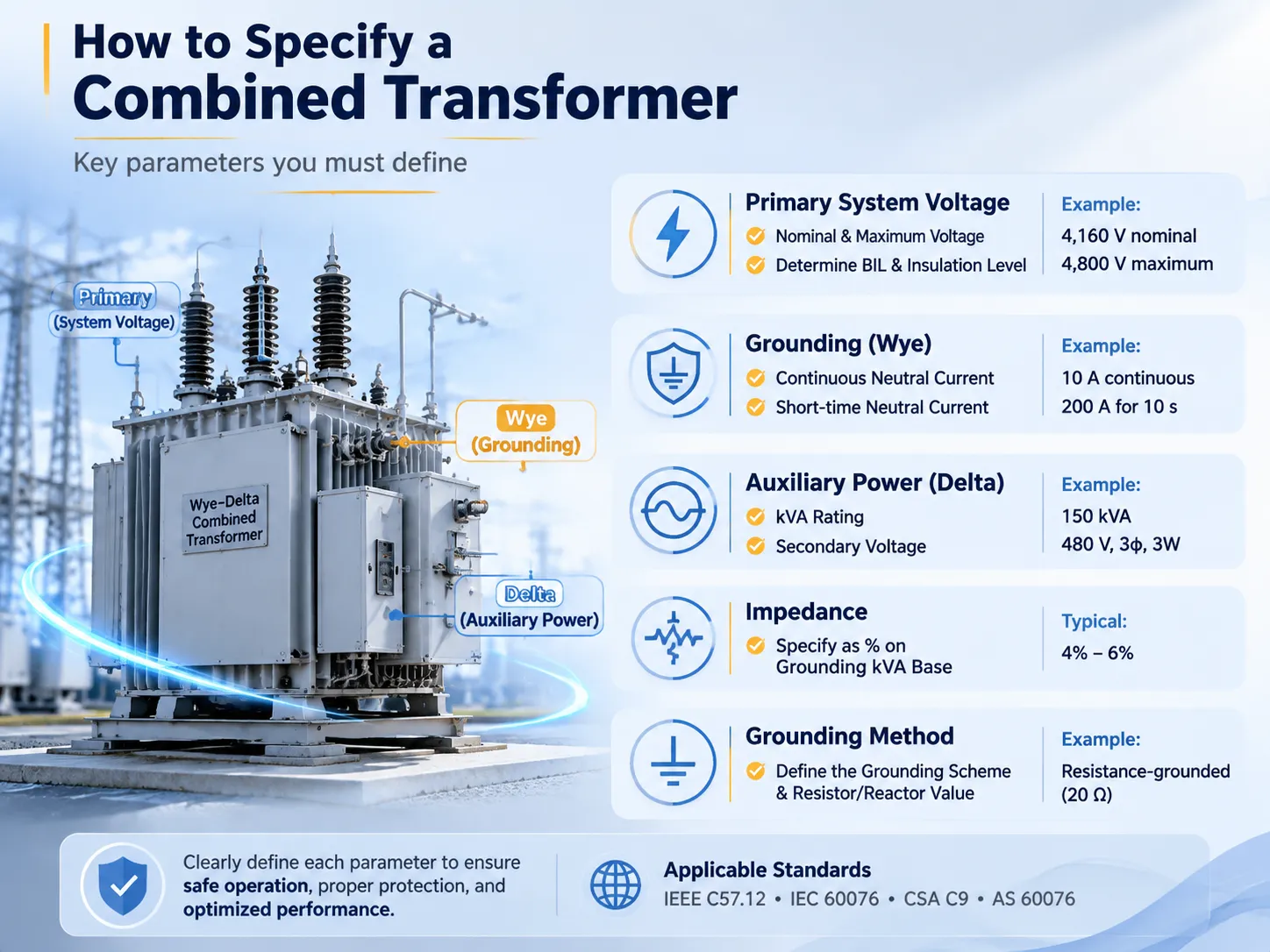
Specifying a combined transformer correctly requires the buyer to define every electrical function that the transformer must perform, and to provide the manufacturer with the specific values — the voltages, the kVA ratings, the impedance, the grounding method, the temperature rise, and the applicable standard — for each function. The key parameters that must be included in the specification are summarised in the table below for the most common combined‑transformer configuration: the wye‑delta grounding transformer with an auxiliary power secondary.
| Parameter | What It Defines | How to Specify It |
|---|---|---|
| Primary system voltage | The line‑to‑line voltage of the system to which the transformer’s primary winding will be connected. This determines the transformer’s voltage class, its BIL rating, and the insulation level of the primary windings and bushings. | State the nominal system voltage and the maximum system voltage. For a 4,160‑volt system, specify “4,160 V nominal, 4,800 V maximum.” The BIL should be specified based on the system’s expected lightning and switching surge environment — typically 60 kV BIL for a 4,160‑volt system, 95 kV BIL for a 13,800‑volt system. |
| Grounding kVA and neutral current | The thermal capacity of the grounding (wye) winding. This is not the same as the auxiliary power kVA. The grounding kVA rating determines how much ground‑fault current the transformer can carry, and for how long. | Specify the continuous neutral current (the current that the neutral can carry continuously under normal, unbalanced conditions — typically a small value, 5–10% of the system full‑load current) and the short‑time neutral current (the current that the neutral can carry for the duration of a ground fault — typically 10 seconds, 30 seconds, or 1 minute). For example: “Continuous neutral current: 10 A. Short‑time neutral current: 200 A for 10 seconds.” |
| Auxiliary power kVA and voltage | The power that the delta secondary winding will deliver to the station service loads. This is a standard three‑phase, three‑wire output. | State the kVA rating and the secondary voltage. For example: “Auxiliary power: 150 kVA, 480 V, three‑phase, three‑wire.” The kVA rating should be determined by a load calculation for the station service loads, with a margin for future growth. |
| Impedance | The transformer’s impedance determines the voltage drop under load and the magnitude of the ground‑fault current. A lower impedance results in a higher ground‑fault current and better voltage regulation but a higher fault‑current duty on the downstream equipment. | Specify the impedance as a percentage on the grounding kVA base. For a resistance‑grounded system, the impedance is typically 4–6%. The impedance should be coordinated with the grounding resistor and the protective relaying scheme. Consult an electrical engineer if the system includes multiple sources or parallel transformers. |
| Grounding method | How the neutral point of the wye winding will be connected to ground. The grounding method determines the magnitude of the ground‑fault current and the type of protective relaying that will be used. | State the grounding method and the grounding resistor or reactor value. For example: “Resistance‑grounded, 20‑ohm grounding resistor, limiting the ground‑fault current to 200 A at 4,160 V.” The grounding resistor is a separate device, but the combined transformer must be designed to work with it. |
| Applicable standard | The standard to which the transformer must be designed and tested. This determines the test procedures, the acceptance criteria, and the documentation that the manufacturer must provide. | Specify IEEE C57.12.01 for dry‑type transformers, IEEE C57.12.00 for oil‑filled transformers, or IEC 60076 for international applications. If the transformer will be installed in a specific country, specify the national standard that applies — for example, CSA C9 in Canada, AS 60076 in Australia. |
The 80% Rule and Other Loading Considerations for a Combined Transformer
The 80% rule for transformers states that transformers must not be operated continuously above 80% of their KVA rating, and this applies to combined transformers as it does to regular transformers, but it must be applied separately for each individual function of the transformer. The grounding winding must be designed for the continuous and short-term earth fault current it will carry in case a fault occurs, and the 80% rule does not apply to the grounding winding in the same way it applies to continuous loads, because this winding operates only under abnormal conditions, and the short-term capacity is more important than the continuous rating. The auxiliary winding must be rated at 125% of the load it is serving, and the 80% rule means that the transformer must be operated not above 80% of its auxiliary KVA rating. Thus, a transformer working with a 150 KVA auxiliary winding for 120 KVA loads is acceptable, but if it is used with a 150 KVA auxiliary winding for a 150 KVA load, it will be undersized — it will get hot, insulation will age faster, and the operating life will decrease. The IEEE C57.96 standard gives information on transformer loading and its relationship with the insulation life and temperature for both oil transformers and dry ones, and a buyer who follows these requirements at the design stage will get a transformer designed for the actual load.
Efficiency, Losses, and the Total Cost of Ownership
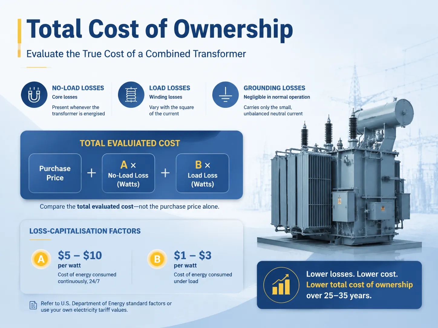
A combined transformer has both no‑load losses (the core losses, which are present whenever the transformer is energised) and load losses (the winding losses, which vary with the square of the current). The auxiliary power winding’s load losses are the dominant loss component when the station service loads are operating, and the grounding winding’s losses are negligible during normal operation because the grounding winding carries only the small, unbalanced neutral current. The buyer who is comparing bids for a combined transformer should evaluate the losses using a loss‑capitalisation formula that converts the annual energy losses into a present‑value capital cost, and should compare the total evaluated cost — purchase price plus the capitalised value of the losses — rather than the purchase price alone. The formula is: Total Evaluated Cost = Purchase Price + (A × No‑Load Loss in Watts) + (B × Load Loss in Watts), where A and B are the loss‑capitalisation factors in dollars per watt. The A factor reflects the cost of the energy that is consumed continuously, 24 hours a day, and it is typically $5 to $10 per watt for industrial and utility applications. The B factor reflects the cost of the energy that is consumed under load, and it is typically $1 to $3 per watt. The U.S. Department of Energy publishes the standard loss‑capitalisation factors for different types of facilities, and the buyer can use these values, or the specific values from their own electricity tariff, to compare bids on a total‑cost basis. A combined transformer with a higher purchase price and lower losses will often have a lower total evaluated cost than one with a lower purchase price and higher losses — and the difference can be substantial over a 25‑ to 35‑year service life.
Frequently Asked Questions
What is the 80% rule for transformers?
According to the 80% rule, the transformer must not continuously be loaded beyond 80% of the rated kVA on the nameplate; hence this provides thermal headroom to prevent the insulation from aging too rapidly as well as facilitates the load growth without the need of installing larger transformer and provides the possibility of accommodating short-term overloads without tripping the protective devices of the transformer. The rule is deduced from the IEEE C57.96 loading guide and serves as the industry standard for transformer sizing.
How do I know which transformer I need?
In order to figure out the transformer that one should use, one needs to jot down all the demands that the transformer might have to satisfy and derive total kVA connected in the end. After that, choose the transformer based on the position—outdoor or indoor as well as whether or not the type of transformer needs to be dry-type or oil-filled according to the requirements of the civil code. After this, the rating of the transformer that is to be chosen should be (the standard one) the upper one and the actual load taken into account in order not to exceed the 80% rule concerning the transformer’s continuous work. The frequency should also be considered.
How to choose the right current transformer?
Choosing the correct current transformer (CT) requires you to determine the primary current (maximum load current that the CT has to measure), the secondary current (A CT usually has a secondary current of 5 A or 1A for metering and protection), accuracy class (defines error of the CT at the rated current and burden), burden (impedance of relays, meters and wires that are connected to the CT), and the physical size and installation type of the CT. Besides, the CT must be rated for the voltage of the electrical system and the available short-circuit current. It is important to mention that this is an individual device that is different from a combined power transformer.
How do I determine what size transformer I need?
In order to calculate how big a transformer you need, one needs to figure out the kVA of all the loads attached, apply the demand factors related to every type of load according to NEC or local codes, add all the continuous loads as 125% of the nameplate rating, and select the nearest higher standard kVA from the calculated value. The pieces of information necessary to produce this calculation correctly are a load study report, a copy of the NEC Article #220, and the manufacturer’s kVA rating chart.
References
- IEEE C57.12.01 — Standard for General Requirements for Dry‑Type Distribution and Power Transformers. The foundational IEEE standard for dry‑type transformer design, testing, and performance, including the requirements for combined‑function transformers.
- IEEE C57.96 — Guide for Loading Dry‑Type Distribution and Power Transformers. The IEEE guide that defines the relationship between the load, the temperature, and the insulation life, and the source of the 80% loading rule.
- U.S. Department of Energy — Loss‑Capitalisation Factors for Transformer Evaluation. The regulatory agency that publishes the standard loss‑capitalisation factors for evaluating transformer bids on a total‑cost‑of‑ownership basis.
- NFPA 70 (NEC) — Article 220 (Load Calculations) and Article 450 (Transformers). The National Electrical Code requirements for load calculation and transformer installation in the United States.
In this case, the complication comes with selecting a combined transformer which requires identifying all the roles that the transformer needs to fulfil, including voltage conversion, grounding, auxiliary power supply, and voltage regulation and then determining the specifications of each role in such detail that the manufacturer will be able to achieve all of them at once. With a properly defined combined transformer you reduce the footprint, the cost of installation and the maintenance of the electrical system as opposed to a set of single-function transformers. However, if you fail the specification process, it means your grounding kVA, auxiliary voltage, and impedance are not mentioned, and the manufacturer will use its default product thus failing to meet your requirements. Subian Electric produces combined transformers for the global market. The kVA of these transformers, their voltages, grounding, and required test documentation make them an attractive offer for a professional buyer.