


A maintenance manager of a medium beverage plant was near a 1,250 kVA dry-type transformer which tripped for the second time in a month. The indicator showed high winding temperature, both the fans were on, the room was cool, and the load was only 55 percent. The manager felt that the problem was caused by the controller, but the chief engineer arriving after an hour did not even open the cabinet. He listened, tested winding resistance on all taps, and pointed to the bolts fixing the core. The looser the core, the higher the vibration which caused connection loosening, resistance increase, and temperature increase.
This article describes the core components of a dry-type transformer, the duties of each component, how it can fail, and what to look for while checking the transformer. Regardless of whether you are the one buying, designing, or maintaining these devices, the understanding of the components is crucial for the accurate diagnosis in a matter of minutes.

What makes up a dry-type transformer?
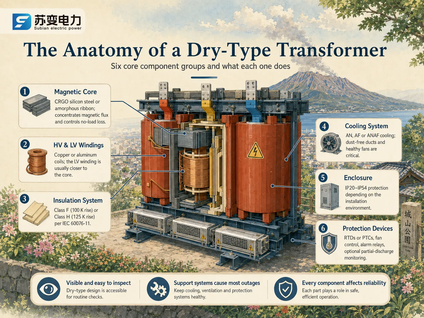
If you look inside the casing of a dry-type transformer, you will find it contains a laminated magnetic core, two concentric coils, a solid insulation system, and a built-in cooling circuit. But besides these parts, the dry-type transformer also includes the circuitry needed for monitoring and controlling the parts mentioned earlier. The fact that all different components in a dry-type transformer are clearly exposed is what makes dry-type models easier to inspect than oil-filled transformers. Because all the different parts are visible, it becomes easier to spot the possible failed systems, unlike in the case of oil-filled units where possible sources of failure will remain hidden from the eyesight of a technician.
Component 1: The Magnetic Core
The magnetic flux passes through the cores, allowing the energy flow between windings. The cores are made of thin sheets, with the most common size ranging from around 0.23 to 0.30 mm grain-oriented silicon steel up to around 0.02 – 0.03 mm amorphous ribbon for the low-loss designs, to either stack or wrap to minimize eddy current effects.
| Core Property | Effect on Transformer | Failure Symptom |
|---|---|---|
| Core material grade | No-load loss level | Rising no-load loss on retest |
| Lamination thickness | Eddy-current losses | Higher than expected core heating |
| Clamping tightness | Mechanical stability, noise | Vibration, humming, loose connections |
| Core bolt insulation | Prevents circulating currents | Hot spots, abnormal heating |
Core problems are rare but serious. Loose clamping is the classic one — it amplifies vibration, which works loose adjacent connections over months, exactly the failure sequence our beverage-plant supervisor encountered.
Component 2: HV and LV Windings
The windings are the areas responsible for converting voltage. The LV winding closest to the core is usually made of foil-wounded copper or aluminum, while the HV winding is either cast in epoxy resin or wound in the open using vacuum impregnation with varnish. Copper has the advantage of carrying less load since it can take more current compared to aluminum, which leads to lower manufacturing expenditure by 20 to 35% depending on the size of the wire.
| Winding Aspect | Cast-Resin (SCB) | VPI (SG) |
|---|---|---|
| HV coil construction | Epoxy vacuum-cast, solid | Varnish-impregnated, open |
| Typical partial discharge | < 10 pC at 1.1 × rated voltage | < 20–50 pC depending on design |
| Moisture resistance | Excellent (sealed resin) | Good, needs dry environment |
| Repairability | Coil replacement typical | Re-impregnation possible |
| Typical use | Buildings, data centers | Industrial, mining |
Winding failures usually trace to hotspots from loose connections or to moisture ingress in VPI units. On any transformer, the winding-resistance test across all taps is the fastest indicator of a developing connection problem.
Component 3: The Insulation System
The insulation system has to endure transients’ electrical and thermal stress and operating voltage for up to 20–30 years of thermal cycling. The insulation of dry-type transformers consists of solid materials classified according to their temperature rating under IEC 60076-11: B class (80 K rise); F class (100 K rise); or H class (125 K rise). This class establishes the thermally allowable heating of the winding materials.
F class (100 K, 155 °C maximum hot-spot temperature): Used in cast resin transformer manufacturing.
H class (125 K, 180 °C maximum hot-spot temperature): Implemented in high-temperature industrial surroundings where ambient temperatures are high.
A basic engineering rule says: for every 6–10 K of excessive heating above the class limit, insulation lifetime is halved. Thus, a transformer that runs a few degrees above its permitted temperature range has a shorter service life than indicated.
Component 4: The Cooling System
The categories of air-cooled method can be simply classified as AN (natural air or free convection) and AF (forced air or fan cooling), and combined form of ANAF. The reason dry type coolers cost more per kVA than oil coolers is because air offers poor cooling performance as opposed to oils, and therefore dry types have to be either de-rated or possess larger cooling surfaces instead.
| Cooling Class | How It Works | Capacity Effect | Maintenance |
|---|---|---|---|
| AN | Natural convection through cooling ducts | Baseline rating | Keep ducts dust-free |
| AF | Fans force air over windings | +25–40% with fans on | Fan bearings, contactors |
| ANAF | Natural base, fans kick in at temperature setpoint | Fans cover peak loads | Thermostat checks |
Dust can be a huge problem when it comes to the cooling process of transformers. The accumulation of dust on the winding surfaces can result in higher values of thermal resistance — even a paper-thin layer of dust can raise winding temperature substantially, without a sound. Regular duct cleaning is the most efficient solution for the problem.
Component 5: Enclosure and Protection Devices
The enclosure has an IP rating ranging from IP20 to IP54 based on specific circumstances: IP20 for dry indoor locations, IP23 for wet industrial locations with drip shields, and IP54 for semi-outdoor or dusty locations. Included in the protective system are temperature measuring RTDs or PTC thermistors in the windings, a control cabinet with alarms, and optional partial discharge monitoring for critical machines. There is very little additional consumption of power by fans: 0.5-1.5% of the total capacity when motors are running and 0 consumption when in startup mode.
How the Components Work Together
The comprehension of components as a system makes clear most operations. When the load increases, rising winding current results in load losses that generate heat in copper and dissipate it through the resin or varnish to the surrounding air. The core, on the other hand, always suffers losses of no-load in every second regardless of load conditions. It means that when ambient temperature rises, temperature of winding will increase and insulation life will reduce. The thermal sensor just sees the outcome; the physics is in the components that were described above.
Component Failure Patterns to Watch For
| Component | Common Failure Mode | Early Warning | Typical Fix |
|---|---|---|---|
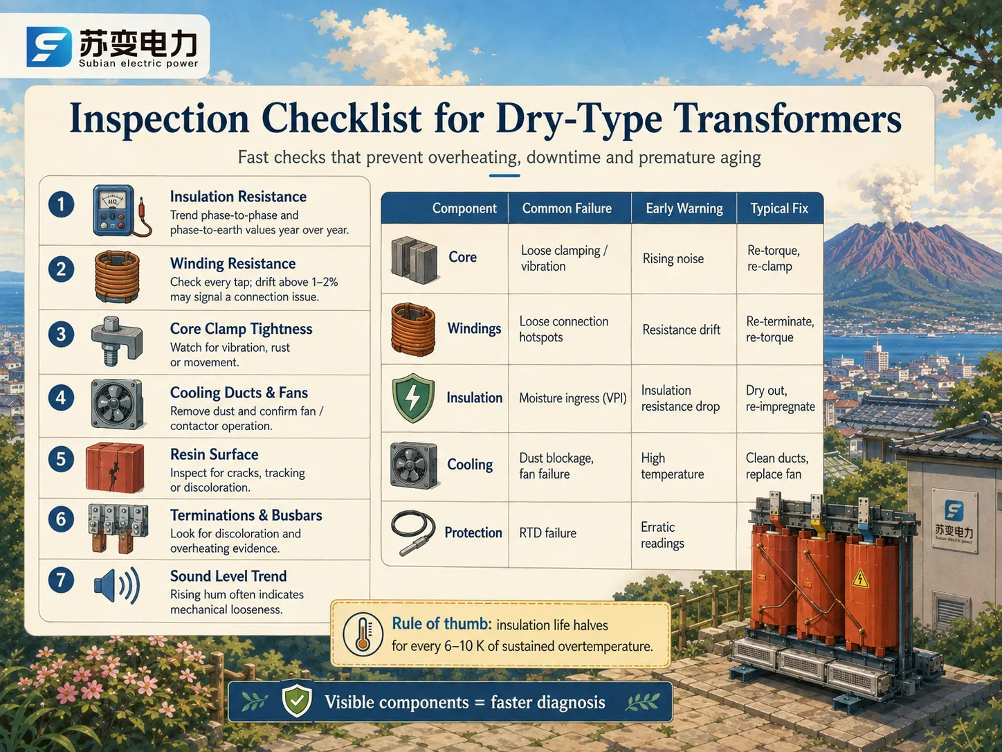
| Core | Loose clamping / vibration | Rising noise, loose bolts | Re-torque, re-clamp |
| Windings | Loose connection hotspots | Winding resistance drift | Re-terminate, re-torque |
| Insulation | Moisture ingress (VPI) | Insulation resistance drop | Dry out, re-impregnate |
| Cooling | Dust blockage, fan failure | Higher than usual temperature | Clean ducts, replace fan |
| Protection | RTD failure | Erratic temperature readings | Replace sensor |
What to Check During Inspection
Insulation resistance tests (megger) from phase-to-phase and to earth should be monitored year-of-year; consistent decreases would indicate a moisture problem.
Winding resistance readings from each tap position should be compared with factory values; deviations greater than 1-2% are indicative of connection issues.
Check the tightness of core clamps and for signs of movement or rust on the core.
Cooling ducts should be clear of dust; also check the operation of fans and contactors.
The resin surface of the cast resin units should be checked for cracks, tracking, or discoloration.
Examine electrical connections and busbar joints for signs of discoloration (signs of overheating).
What Components Do to the Price
The price of a dry-type transformer is largely a component cost story: copper is roughly half the material value, core steel or ribbon a quarter, and resin, enclosure, and protection the rest. That is why prices track copper markets and why amorphous cores add 20–40%. Indicative FOB ranges; prices vary by specification, brand, and region.
| Rating | Cast-Resin, CRGO Core | Cast-Resin, Amorphous Core |
|---|---|---|
| 100 kVA | $3,000–$6,000 | $4,000–$7,500 |
| 250 kVA | $6,500–$11,000 | $9,000–$15,000 |
| 400 kVA | $9,000–$16,000 | $12,000–$20,000 |
| 1,000 kVA | $20,000–$38,000 | $25,000–$45,000 |
| 2,500 kVA | $45,000–$85,000 | $55,000–$95,000 |
Frequently Asked Questions
What are the main components of a dry-type transformer?
Six groups: the magnetic core (silicon steel or amorphous ribbon), HV and LV windings (copper or aluminum foil), the insulation system (F or H class), the cooling system (AN/AF), the enclosure (IP20–IP54), and protection devices (RTDs, fans, control wiring). Each contains different modes of failures; winding resistance and insulation resistance tests are capable of checking most of them at once.
Which component fails most often in dry-type transformers?
In terms of operation, connection and cooling issues dominate: loose connections lead to hotspots and dust-blocked ducts lead to overheating. Core failures are uncommon but very serious. Both types of failures can be avoided if regular maintenance is conducted — resistance trending and duct cleaning alone are sufficient to avoid most unplanned outages.
How much does a dry-type transformer cost by component?
Copper typically accounts for roughly half of material cost, core steel or ribbon about a quarter, and resin, enclosure, and protection the remainder. This is why prices track copper markets. A complete 1,000 kVA cast-resin unit runs about $20,000–$38,000 FOB, with amorphous cores adding 20–40%. Prices vary by specification, brand, and region.
What is the difference between F class and H class insulation?
Per IEC 60076-11, F class allows a maximum average winding temperature rise of 100 K (155 °C hot-spot limit), while H class allows 125 K (180 °C limit). H-class units tolerate higher ambient temperatures and overloads but cost slightly more; F class is standard for most building and data-center applications.
Why are dry-type transformers more expensive than oil-immersed ones?
Because air cools far less effectively than oil, a dry-type needs more copper and a larger core to stay within insulation-class temperature limits — roughly 25–40% more material cost at the same rating. The premium buys fire safety, no oil maintenance, and code-friendly indoor installation.
References
- IEC 60076-11: Dry-Type Power Transformers — The standard defining dry-type transformer insulation classes, cooling, and tests.
- IEEE — Publisher of IEEE C57 series on transformer testing, thermal life, and maintenance.
- NEMA — North American standards body covering transformer enclosures and efficiency.
- NFPA 70 (National Electrical Code) — The code governing transformer installation and clearance.
- US DOE Distribution Transformer Standards — Efficiency rules that shape core and winding design.
- Jiangsu Subian Electric Power Co., Ltd. — Manufacturer of cast-resin and VPI dry-type transformers with component-level test documentation.
Conclusion
Every dry-type transformer is the sum of six component groups — core, windings, insulation, cooling, enclosure, and protection — and each group has a distinct job, a distinct failure mode, and a distinct contribution to the price. Knowing the anatomy turns vague warnings like “temperature high” into a structured diagnosis: measure resistance, check clamps, clean ducts, inspect resin. It also explains the cost structure, from copper-heavy windings to amorphous-core premiums, and why insulation class F versus H is a real engineering decision. For buyers and maintainers alike, the practical path is the same: demand per-unit test data from your supplier and inspect the visible components on a schedule. A certified manufacturer such as Jiangsu Subian Electric Power provides the documentation that makes component-level confidence possible.