


A current transformer (CT) is a device used with a metering/protecting system for measuring large amounts of current/levels that are not directly measurable; it converts current from 400, 1000 and 3000 A into a usable value of 5 or 1 A. This change happens under certain conditions that must be followed by the CT device: polarity must be correct, the burden must be accurate, secondary wiring should never be exposed to an open circuit while current is flowing. The manual includes specifications about the wiring connection of CTs with measuring, relay and monitoring devices, how to set wiring up step-wise and the way three-phase models should be wired.
In case the primary current or conductor connected to the device is allowed to be passed through the transformer P1 and P2, then the reading recorded at the secondary terminals P1 and P2 could be wrong due to the fact that S1 might not be matching with P1 in all the cases leading to a voltage reading of the current at S1 S2 connections. When using a single transformer, both S1 and S2 connections are unused with respect to all three-phase connections. There is no requirement for any other method of connection if a single CTs is used since it will always be a direct connection for the two of S1 and S2. In case of three-phase wiring, the transformer should be connected using the “Y” or star connection method with S1 being connected to the three instrument inputs where the use of S2 connections is done at the union point where S2 will get connected at the common star point regardless of any of the two methods above being used.
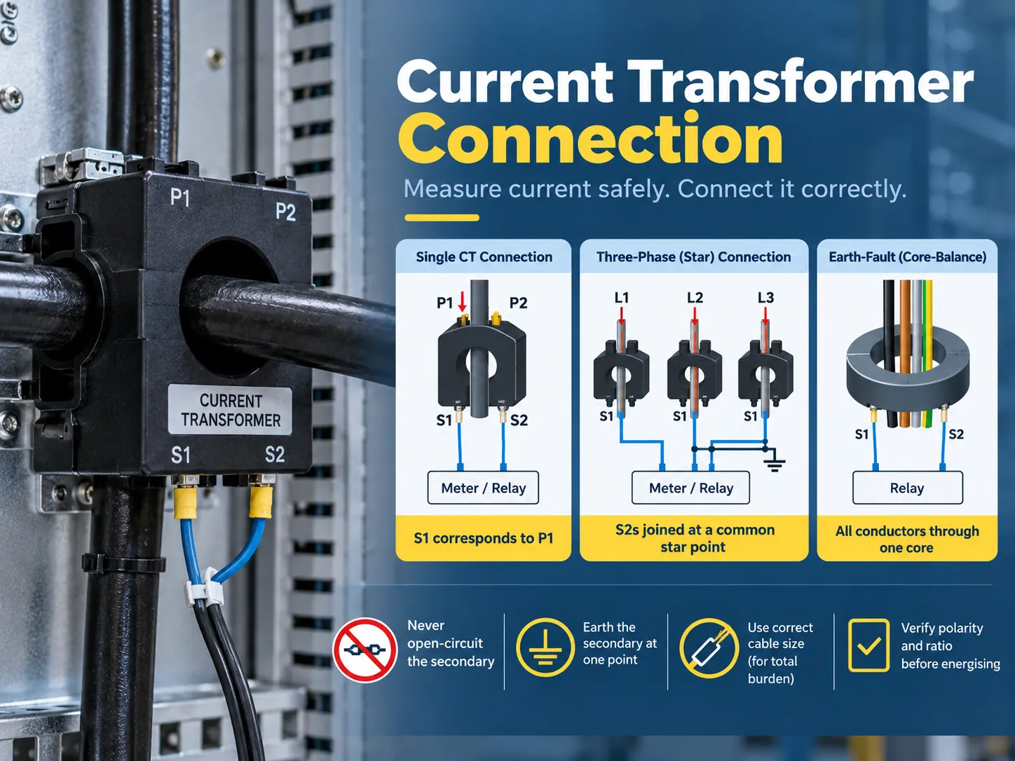
What a current transformer does, and why connection matters
CTs are specialized transformers that can only work in one manner: taking the primary current and producing a proportional secondary current while guaranteeing insulation from the primary circuit. A 400/5 CT produces five amperes at the secondary when the primary has an electric current of 400 amperes. In addition, it provides two and a half amperes at half load, and the connected meter or relay will interpret this information and take it back to the primary.
| CT type | Construction | Typical use |
|---|---|---|
| Bar-primary (window) CT | The primary is a fixed bar or the busbar passes through the window | Switchgear, panel metering, retrofit around existing bars |
| Wound-primary CT | The primary is a winding brought out to terminals (P1/P2) | Low-ratio and special-ratio applications |
| Split-core CT | Clamps around an existing conductor without disconnection | Retrofit energy monitoring, sub-metering |
| Bushing CT | Built into a transformer or breaker bushing | Transformer and switchgear protection |
| Core-balance (zero-sequence) CT | All phase conductors pass through one core | Earth-fault detection and sensitive leakage measurement |
There are two important factors that show how a CT should be connected. The ratio for the secondary current means how much current the CT will provide for a certain primary current (for example 400/5 or 1,000/1). The burden in VA indicates the amount of load (metering and relaying) that must be attached to the CT without affecting its performance. Thus, if a CT is working according to correct ratio but is burdened improperly, the readings will not be accurate.
Terminals and polarity: P1, P2, S1, S2
CT terminals adhere to an established convention whereby wiring is always unambiguous once the letterings are understood:
| Terminal | Meaning | Connection rule |
|---|---|---|
| P1 | Primary, polarity-marked side | Usually faces the source (the incoming side of the conductor) |
| P2 | Primary, non-marked side | Faces the load |
| S1 | Secondary, corresponds to P1 | Connects to the instrument input marked S1 (or the “line”/polarity input) |
| S2 | Secondary, corresponds to P2 | Connects to the instrument input marked S2, or to the star/common point in three-phase schemes |
The polarity rule is a major source of commissioning failures. Because S1 has to always match with the S1 input of the instrument, and P1 with the source, a change in either the orientation of the CT or the landing from S1 to S2 will cause the currents measured to be reversed. Direction sensitive protection applications may fail as well as the readings of power (kW) in which import may show as export. On the other hand K & L as markings may be used by some manufacturers, the principle remains the same (K is to correspond with P1 and L with P2), meaning that nameplate must dictate the wiring and not the way of life.
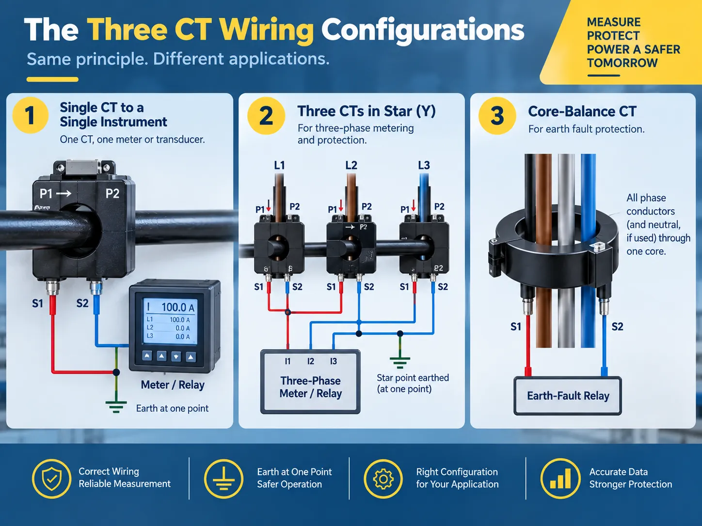
The three wiring configurations you will actually use
Almost every installation of CT is divided into three types of configuration:
- One CT used in conjunction with a single instrument. One CT with a meter or sensor: S1 is connected to S1 of the instrument, and S2 is connected to S2 of the instrument, while the secondary side is grounded at one spot (usually at the instrument panel). This is the standard way of using it for a dedicated feeder panel or motor current monitoring. The same procedure is repeated three times in the case of three-phase, four-wire metering.
- Use of three CTs in a Y-configuration for three-phase metering and protection. Here, all three S1 wires are connected to the corresponding instrument current input, while all three S2 wires are brought to a single star point. This star point is the point where the secondary is grounded. The star configuration is used as the default configuration for three-phase energy meters and power meters since it provides an accurate copy of the phase currents and also provides a path for current imbalances.
- A core-balance CT is used for earth fault detection. In this case, all three phase conductors (and the neutral, depending on the application) are passed through the one CT core. In a normal condition, the vector sum of the currents equals zero, and so the CT secondary reads zero; any earth fault leads to some current returning through earth instead of through the neutral and produces a residual signal that is detected by the earth-fault relay. The wiring is less complicated in this setup (only two secondary wires go to the relay), but certain physical rules have to be adhered to: no other wires can go through the core, and the cable shield or armor cannot create a parallel route that cancels the residual current.
If the same CT needs to provide data for both a meter and a protection relay, then the two loads are wired in series (the meter first, then the relay, or by using alternate cores if the CT has multiple secondaries) and not in parallel or with unused cores.The protection philosophy behind residual connections is explained further in our earth fault protection basics guide.
The CT connection diagram, explained
One must read a CT wiring schematic starting from the primary side and ending at the instrument. This is an example of what a three-phase metering installation would look like when presented in a diagram:
| From | To | Conductor |
|---|---|---|
| Phase A conductor (source side) | CT-A P1 | Primary circuit — not CT wiring |
| CT-A S1 | Meter current input IA (S1) | 2.5-4 mm² copper, 600 V rated |
| CT-A S2 | Star point | Same size as S1 |
| CT-B S1 | Meter current input IB (S1) | Same size |
| CT-B S2 | Star point | Same size |
| CT-C S1 | Meter current input IC (S1) | Same size |
| CT-C S2 | Star point | Same size |
| Star point | Earth (one point only) | Grounding conductor per local code |
| Each S1/S2 pair | Shorting/test terminal block | Installed between CT and instrument |
If your project has a supplied wiring diagram, it should be used as the primary source document. However, all of the following three conventions should be used to verify it before you finalize the installation: use of S1 to S1 pairing, use of a single earth point, and presence of a shorting mechanism in the circuit. Any discrepancies in these three aspects can lead to improper commissioning and create unsafe conditions.
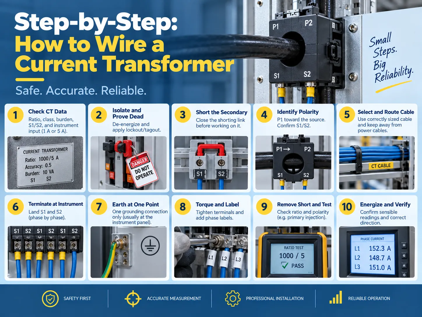
Step-by-step: how to wire a current transformer
- The first step is to verify the CT data and check the instrument demands. Check the nameplate for the ratio, accuracy rating, burden (VA), and polarity markings. Confirm the input rating of the instrument (1 A or 5 A) is consistent with the CT secondary because if a 5 A CT is connected to a 1 A input, the instrument will read inaccurately by a factor of five and may saturate the input.
- The device must be isolated, followed by the verification of the dead condition. The primary circuit must be de-powered, and proper lockout/tagout measures must be applied. It is important to remember that “even if the primary circuit has been isolated, there may still be a live CT secondary that is energized from another source” and hence it is important to consider every CT circuit live until proven otherwise.
- The next step is to short the secondary circuit. The shorting link on the testing terminal block needs to be closed or a proper shorting device may be used to connect S1 and S2. This procedure eliminates the danger of CT failure.
- The next step is to find the polarity that involves locating the points P1 and P2 of the primary as well as S2 and S1 for the secondary. It is essential to confirm that the primary orientation (where P1 points toward the source) and the physical arrangement matches the diagram.
- Select the proper secondary cable. Copper conductors of the appropriate size need to be used for both the burden and run length (standard 2.5 mm², 600 volts) with the goal of avoiding running power conductors in the sheath while achieving all three phases.
- Termination needs to happen at the instrument with S1 in the S1 (polarity) input on the instrument and S2 on the second input.
- Ensure that there is a grounding at only one point, typically at either the instrument or relay panel.
- Check the terminals for torque settings according to the manufacturer and apply labels to the phases including the ratio label.
- The shorting link must be removed before testing commences with the verification of the ratio and polarity.
- Turn the energizing circuit on so the circuit is reading correctly on the instrument with all three phases being noted at the current reading.
Burden and cable sizing: the calculation most installers skip
Current transformers (CTs) have a rated burden above which they will not be accurate. The burden total includes all devices connected to the secondary and the resistance of the secondary wiring:
- Instrument burden: this is the VA burden (or ohmic) specified by the manufacturer of the meter or relay. It can vary by instrument type, but is generally in the range of 0.2-1 VA per current input for modern electronic instruments and higher burdens for older electromechanical relays.
- Wiring burden: the wiring resistance is calculated as follows: 2 x one-way length x resistance per meter (for example, the resistance for 2.5 mm2 copper wiring is approximately 7.4 ohm/km), times the square of the secondary current. Depending on the run length, it is not uncommon for the instrument burden to be exceeded simply due to wiring burden.
- Connection burden: the resistance across the terminals and test blocks is generally small, but if the wiring total is close to the CT burden, this value should be included.
If the total burden exceeds the rating of the CT, it cannot provide accurate readings and may saturate during fault currents – which is when protection is needed most. Possible remedies include a shorter cable run, a larger conductor, using a lower-burden instrument, or buying a CT with a higher VA rating.
The accuracy classes themselves — 0.5 and 1 for metering, 5P and 10P for protection — are explained in our transformer accuracy classes guide.
And the ratio-selection logic for a given installation, from load current and fault level to the final nameplate choice, is covered in our current transformer ratio selection article.
Testing and verification
Three tests are used to ensure that a CT is installed correctly before it is allowed to carry load:
| Test | What it proves | Method |
|---|---|---|
| Ratio test | The CT produces the expected secondary current for a known primary current | Primary injection at a fraction of rated current, or a secondary-voltage method for large CTs |
| Polarity test | S1 truly corresponds to P1 and the instrument reads forward power correctly | DC pulse or primary injection with a polarity-sensitive instrument |
| Insulation and continuity | No shorted or open secondary conductors, and adequate insulation to earth | Insulation resistance and continuity checks before energization |
Post-energization verification is equally important because you should compare the readings of the CT with a reading from a clamp meter on the primary side, verify that the readings are consistent across all three phases, and confirm that the earth-fault circuits register zero residuals on a healthy feeder.Where the CT is part of a protection scheme, that coordination — and the grounding references it depends on — is the subject of our transformer grounding basics guide.
Safety rules, and the mistakes that damage equipment
The secondaries of current transformers only flow small amounts of current at low voltages—until something goes wrong. The following are mandatory guidelines for dealing with current transformer circuits:
- Never open the current transformer circuit secondaries while the primary circuit is energized. The current transformer will attempt to generate very high voltages (hundreds or thousands of volts) across the secondary terminals when it is open, leading to an extreme overvoltage situation, core saturation, overheating, and potentially explosion and fire.
- Ground the current transformer secondary only at one point. Connecting the ground at two points will cause unnecessary current to circulate through the ground contributing to an incorrect measurement and potentially causing an unnecessary trip of protection equipment.
- Avoid installing a switch or fuse in the current transformer circuit that is not a shorting type of test block. Standard circuits may fail open which creates the same condition as an open circuit.
- Do not leave spare current transformer cores open. Short the unused coils and note them on the drawing, or future technicians may be incorrectly leading service personnel to assume that they are open circuits.
- Be sure to observe proper polarity at each connection. The S1-to-S1 and P1-to-source connections are not arbitrary conventions that may be changed later.
- Keep current transformer wires away from power and variable frequency drive (VFD) cables, and do not pass the current transformer around just a single part of the conductor in a core balance scheme.
Two other practical points to remember are that a current transformer must be hooked up with the instrument input rating matching the transformer’s secondary rating (either 1A or 5A) and that the primary conductor must pass through the window in one direction only. Passing a bar or cable back through the core backwards will reverse the effective polarity of the current transformer.For meters that must be removed for calibration, the test block should be the type that automatically shorts the CT when the instrument is unplugged; the wiring practices around metering and instrument transformers are also covered in our current transformer installation guide.
FAQ
What are the disadvantages of using a current transformer?
There are several drawbacks; having an open-circuit secondary is dangerous since it creates the possibility of serious injury; calculation of the connected load must be done correctly, or else inaccurate readings will be produced; incorrect polarity can result not only in inaccurate readings but also in malfunctioning protection devices; there is a small phase shift introduced by the CT that results in a slight inaccuracy in measurements; added expense and panel space; proper sizing is necessary, otherwise, the CT will saturate during a fault condition. Although modern electronic meters do reduce some of the problems associated with these drawbacks, all of them cannot be eliminated.
How are current transformers wired?
To connect the primary conductor through the CT there is P1 (the source side) and P2 (the load side) or the line is passed through the bar / window. The secondary side will be S1 and S2 with S1 corresponding to P1. The S1 and S2 will lead to either a meter, relay, or transducer directly for a single CT or in a star configuration for three-phase metering (three S1s to the meter and three S2s coupled to one grounded star point, etc.). There is a shorting/test terminal block mounted at the juncture of the CT and the instrument.
Does it matter which wire goes where on a transformer?
For any transformer it does; however, CTs have unique requirements. This is due to the leads having a specific polarity (i.e., S1 correlating to P1). By reversing these two leads, it causes current to flow in the opposite direction creating inaccurate power readings along with the possibility of malfunctioning protection devices. This is applicable in both transformers with respect to the primary and secondary leads.
How do you connect an electrical transformer?
In the case of an instrument transformer such as a CT: verify the ratio and the burden, isolate the transformer and prove it to be dead, short out the secondary side, identify which lead corresponds to P1 and which lead corresponds to S1; connect the correctly sized secondary cable such that S1 and S2 lead to the instrument’s respective inputs, ground the secondary at one point, label and torque the connection, remove the ground; and finally inject a known standard into the system to verify polarity and ratio. The process for connecting a power transformer differs from this procedure but still requires the individual to verify ratings, polarity, grounding, and testing before energizing load.
References
- IEEE — C57.13, Standard Requirements for Instrument Transformers
- IEC — 61869 Series, Instrument Transformers
- NFPA — National Electrical Code (Instrument Transformer Circuits)
- NETA — Acceptance Testing Specifications for Electrical Power Equipment
Conclusion
The installation of the current transformer carries a lot of weight although it may seem like an unimportant task. The function of the current transformer is to reduce the amount of primary current flowing through the wire to a safe reading for the meter or relay. Therefore, you can see how important this task is in the long run. For the primary wire (P1) you will have to run wire to the source while the secondary wire (S1) will run from the current transformer to the meter or relay. If you are wiring three-phase meters, the circuits must be wired in a star pattern and grounded at a single point to earth. Use a core-balance CT for residual currents; make sure you size the secondary wire appropriately according to the burden load. Always use a test block to short out the circuit before energizing it and never break the circuit as long as current is flowing through the primary side. Make sure that you check the readings first using primary injection and then record the ratio on the sheet for future reference.