


When you ask one of the experienced relay engineers which protective relay will never be taken out of service on a power transformer, the answer will always be differential relay. Although feeders are reclosable and busbars can be separated, a transformer failure which has not been automatically cleared leads to ruptured tank, oil catching fire and prolonged outage. Differential protection is the quickest and most selective protection available for this type of failure, which is why a modern differential relay operates within 20 milliseconds.
We will now describe in practical terms what the zone includes, how relay makes decisions, what the protection settings are and how CTs are wired depending on the winding design of the transformer in question. If you are looking for transformers or for relay panels rather than for relays, the two last paragraphs will be of interest to you.
Brief answer: Transformer differential protection works by comparing the current coming into the transformer against the current going out of the transformer. If everything is fine, then the two currents will be the same; however, if the current is unbalanced, the relay will trip. The corresponding ANSI code is 87T. In many systems, however, a percentage biased differential protection circuit is utilized with a pick-up set at about 20-30% of the transformer rated current.
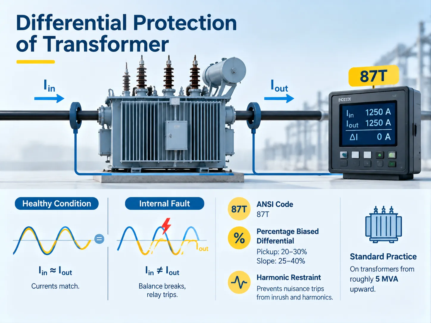
The zone it protects — and the boundary that matters most
A differential protection system shields any machinery located between two sets of current transformers. As far as a transformer with two windings is concerned, this covers windings, core, tap changer, internal wires, and bushings up to the point of CT installation. However, downline feeders and high voltage bus systems that supply electricity to transformers are not included in these arrangements.
This is why placing the current transformers is perhaps the most crucial aspect of designing the whole system. If the high voltage CT is situated too far from the transformer, then any fault occurring in the wire between the switchroom and the transformer will be outside the scope of both differential relay and transformer, and additional earth fault or overcurrent protective devices will be needed to cover that particular stretch of wire. Allowing for maximum proximity of the two current transformers to the transformer essentially removes the gap.
How the differential principle works
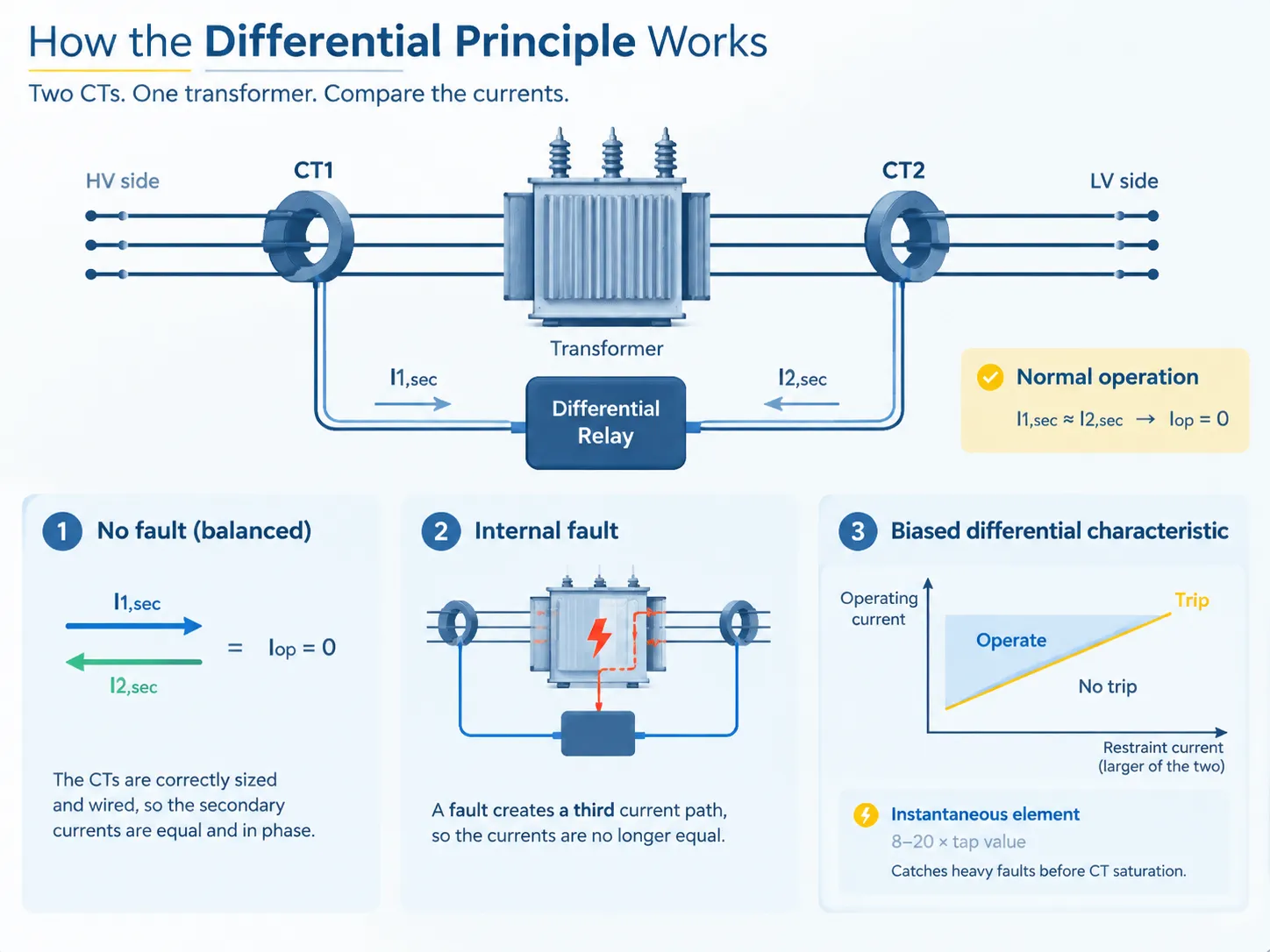
The concept is surprisingly very straightforward. The actual transformer principles do not matter; as simple as that, a transformer can be described as a current transfer device. Therefore, currents on secondary sides of the CTs must be identical. The relay then “looks” for an abnormality or a difference, which is non-existent.That equality only holds if the CTs themselves are correctly sized and wired, which means the scheme inherits every mistake made in the CT circuit — the common CT connection methods used on protection circuits are worth getting right before anything else.
The operational current is basically the vector sum of the two secondary currents produced by the current transformers:
Iop= |I1sec– I2sec|
After the appearance of a fault inside the transformer, a third component appears which was not accounted for by the transformers, hence, the sum could not be zero anymore. But there are two factors that complicate the situation because a transformer always has a magnetizing branch, therefore, there exists some small imbalance which is really a spill or mismatch current even when the system is operating properly. The same can be said about the ratios of the transformer and the operation of the tapping equipment that are also not usually the same for all transformers that face the same situation.
Thus, the only useful relay which one can come up with today could be biased. It is worth mentioning that each current transformer produces the restraint current using the larger value of the two currents (or their average). This means that under normal conditions even if there is some small difference, the current stays within the limits of the restraint current. When a real fault exists, the relay works perfectly.
In addition, most relays also include a special element that reacts straight away under very high level of current (up to 20 times more than the tapping equipment level). This element is necessary because at very high levels of fault current, the current transformer on one of the sides may saturate so badly that the biased measurement fails.
Percentage biased settings that actually get used
The manuals for relays show a huge amount of variation, which is not very helpful when you are faced with a relay commissioning checklist. Here are the settings which are most commonly used in practice for a standard 87T relay:
- Pickup (Id or Is1): 20–30% of the rated transformer current level. Choose 30% if CTs are of low class or if the load is imbalanced, with 20% setting being used only when CTs and wiring are well-matched.
- Slope 1: 25–40%, for range one, which corresponds to normal load and a moderate fault.
- Slope 2: 50–80%, for range two, when fault current is about 2–4 times higher than the rated current. This range corresponds to the CT saturation during a heavy external fault.
- Second harmonic blocking: 15–20%, used for energising blocking the relay so that it is not triggered by inrush phenomenon.
- Fifth harmonic blocking: 20–35%, used for blocking upon operating in over-excitation.
- Instantaneous high set: 8–20 × tap, no harmonic block.
The second harmonic setting deserves a warning too. Conventional blocking seems to presume the presence of the second harmonic in the inrush current. Traditional core technology using high-silicon steel works on this premise, but advanced transformer core technologies, such as amorphous metals, have dramatically reduced the presence of the second harmonic in the inrush current. Thus, blocking the relay at 15% on such transformers may lead to spurious trips after energising. Common solutions involve cross-blocking or waveform-based detection for inrush current. Therefore, if you specify the relays for a transformer with low losses, be sure to ask which method the vendor uses.
CT connections for delta, wye and zigzag windings
Here we can see the difference between classical and modern schemes and the source of many commissioning errors.
In classical electromechanical schemes the CT connection is the same as the connection of the transformer. For Dyn11 transformers the high voltage side CTs have a star connection and the low voltage side CTs have a delta connection. The delta connection resolves two issues at once: it cancels the 30-degree phase shift caused by the delta winding of the transformer and blocks zero-sequence current from passing through the relay when there is an external earth fault.
In a numerical relay all the CTs are connected with star connection. The phase shift, ratio matching and zero-sequence filtering are performed by software. Wiring thus becomes simpler and testing easier, however it also creates one point that often gets overlooked: the relay must block zero-sequence current by means of software just like the delta connection did in hardware. Not enabling this filter may lead to the circuit of the CT working under the influence of the external earth fault making the relay to trip. Make sure to check the settings; the majority of companies provide it but it is not always turned on by default.
Regardless of the technology, three rules must be observed:
- Ratios must match. The CT ratio must be chosen in such a way that the currents are 10% close to each other on both sides at the rated tap in order to avoid losing margin.
- The tap changer must be taken into account. The transformer with ±10% taps changes its ratio by 20% from end to end and that difference must be taken into account in the slope characteristics of the relay; if it is made too steep then sensitivity is sacrificed.
- Polarity must be followed. The convention is that all the CTs are facing the transformer. If you change the orientation of one of the pairs of CTs then instead of the difference the relay will recognize the total current.
If you are working through the wiring on an unfamiliar unit, this walk-through of how to wire transformer delta and wye connections covers the winding side of the same problem, which is useful when you are comparing drawings against the nameplate.
Differential versus REF — and where the scheme falls short
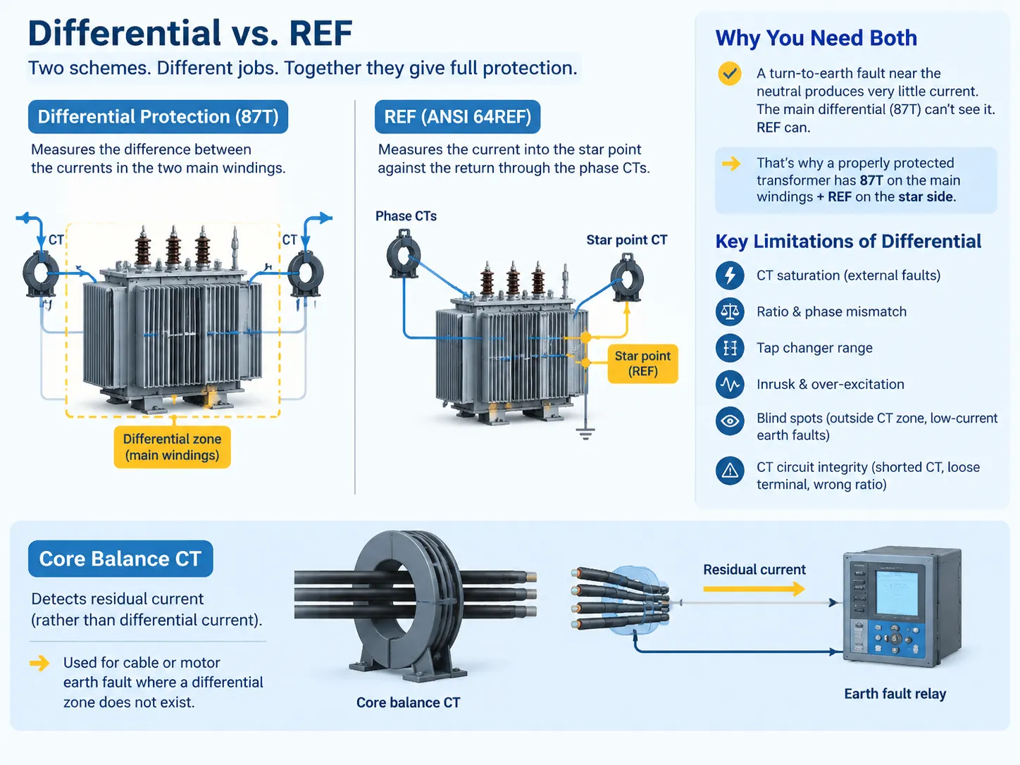
Restricted earth fault protection, which is also called ANSI 64REF or just REF, is said to be “the differential protection of one winding”. This is quite true since REF is a high impedance scheme measuring the current flowing to the star point of one winding against the current returning through phase CTs. Since it detects the current in one winding only, it is much more sensitive than the whole differential scheme, usually being about ten times more sensitive.
Why are both needed? Because in case of the turn-to-earth fault that occurs near the neutral of one star winding, the current will be small and most of it will be circulating in the winding itself rather than going through the differential zone. The overall 87T relay cannot see it. REF can.
We should enumerate the principal drawbacks of differential protection, as they determine settings:
- Saturation of the CTs in case of external faults. A strong external fault can lead to the saturation of one CT circuit thus forming a false differential current. In this case bias, another slope of operation and CTs of sufficient burden can be used.
- Ratio-phase mismatch. Each compensation measure leads to reduced sensitivity of the system.
- Regulating range of the tap changer. The bigger the range of the tap changer is, the bigger differential current must be tolerated, thus the higher slope of operation should be used.
- Current inrush and over-excitation. The problem is solved with the help of harmonic restrain that leads to the reduction of the sensibility of the device.
- Blind zones. The faults are located beyond the CT zone making them invisible.
- Integrity of the CT circuit. I believe that in the majority of cases the problem does not occur due to the transformer operation but for other reasons associated with the circuit work.
For a perspective on how earth fault sensing is built around a different principle, the core balance current transformer is a useful contrast: it detects residual current rather than differential current, and it is what you would use for a cable or motor earth fault where a differential zone does not exist.
Commissioning and ongoing checks
When installing a differential relay, it is important to perform commissioning tests to prevent issues later on. The following are the minimum requirements to be done during tests:
- Check the CT ratio and polarity on both sides in accordance with wiring diagrams. Primary injection testing method is advantageous.
- Test that CT secondary currents are balanced under load; store the measured spill current.
- Prove stability by injecting a through current equal to the external fault current. The relay shouldn’t be activated.
- Prove sensitivity: set a current just over the relay’s acceptable value and check that the relay operates as intended.
- Check harmonic blocking using second harmonic injection.
- Check the CT burden and compare to the rated burden for the CT.
After the commissioning phase of the relay the routine checks include very easy steps: measure and save spill current each year, alter the records of the relay for each through fault and monitor if there are new loads added to the spare CT coil. For a wider view of what else belongs on the annual transformer routine, this transformer maintenance checklist is a reasonable template to adapt to your own site.
Frequently asked questions
What is transformer differential protection?
This is a protection plan which measures the amount of electricity flowing into the transformer against that flowing out of it. When both energies match, it means that there is no short circuit; if there is any difference above the threshold point defined for the protection – an internal failure is detected and the relay sends the trip signal to the transformers circuit breakers through the blocking relay.
What is the ANSI code for transformer differential protection?
The transformer differential relay is given the number 87T. While 87 is the general code for all differential relays, 87T indicates that it has been designed specifically for use with a transformer. Some other codes that may be found on the same panel are 87G or 64REF in relation to restricted earth fault, 87B for busbar differential, 50/51 for time overcurrent back-up, Buchholz or sudden pressure 63, 49 for thermal, and 24 for over-excitation.
How to calculate transformer differential protection?
Carry out the process in five stages. As an example, let us take a 10 MVA, 33/11 kV, Dyn11 transformer.
- Calculate the rated currents. The primary current is 10,000 ÷ (√3 × 33) = 175 A and the secondary current is 10,000 ÷ (√3 × 11) = 525 A.
- Select CT ratios. The CT ratios of 200/1 on the 33 kV side and 600/1 on the 11 kV side give 0.875 A and 0.875 A secondary, which is a perfect match at nominal tap. Ensure that the mismatch does not exceed 10% over the whole tapping range.
- Determine pickup value. It will be 0.25 × 0.875 ≈ 0.22 A; round it up to the available nearest step which is approximately 0.25 A.
- Calculate restaint. The value of restraint is 4 × 0.875 = 3.5 A for a through current of 4 times rated current. The slope at 30% means that the relay has to operate at a current exceeding 1.05 A.
- Test the instantaneous element. For a tap setting of 10, it will give the value of 2.5A.
For what rating of transformer is differential protection recommended?
There are variations in practice depending on utility and the importance of the unit, but the following limits are generally followed. For less than approximately 1 MVA, fuses and overcurrent relays can be used. For values from around 1 to 5 MVA, differential protection starts being employed in critical units and transformers feeding the plant. For values greater than 5 and especially for those over around 10 MVA, the installation of differential protection becomes obligatory. There are two exceptions to that rule. One way is when a transformer is of the kind where replacement is a very complex and/or costly operation. Another reason can be a low level of fault currents compared to a transformer capacity.
References
- Electrical Engineering Portal — Transformer differential protection scheme
- Circuit Globe — Differential protection of a transformer
- Electrical4U — Differential protection of transformer and differential relays
- IEEE Standards Association — IEEE Std C37.91, Guide for Protective Relay Applications to Power Transformers
- SEL — Transformer differential protection application notes
Conclusion
Differential protection in itself is simple: compare the input with the output, and adjust the threshold in such a way that the normal discrepancies do not activate your protection. The problem is in the details: correct placement of CT, ratio matching, zero-sequence filter, use of harmonic block, and tap changer range. Provided these details are correct, the relay of differential protection would work perfectly for a long period of time, activating only when it is necessary. If these details are wrong, they would appear to be mistaken as soon as the transformer is energized.
In case the transformer in question is the one you are sourcing instead of protecting, then we are manufacturing oil-immersed transformers and dry-type equipment complete with all relevant test documentation, thus, you have all necessary nameplate information for CT selection and relay setup before the transformer is dispatched. You could ask for quotation for the transformer including the test report, drawings and tap range, it is in most cases enough for the protection engineer to finalize relay settings without additional emails.