


Based on how this is applied, the transformer/motor information may be thought of to be unnecessary. This is because the transformer, which is connected to the motor through a direct connection, does not have a listed transformer application rating matching the nameplate of the motor in terms of current, therefore it does not provide an accurate rating of the transformer either. The application rating of the transformer is actually based upon the amount of apparent power consumed by the motor as an inverter, and there is no indication of either one of those parameters on the motor nameplate. Two parameters are required in order to create a successful inverter configuration.
In conclusion, the rating selected for the motor-feed transformer should be based on the transformer’s kVA rather than its kW rating. In order to accurately size the transformer, three simulations must be completed; the transformer kVA rating will be twice as large as the highest kVA rated motor, and 1.25 times as large as the total kVA rated for all loads connected to the transformer. Therefore, the motor total load current must not exceed 65% of the total load current of the transformer(s). When starting the motor, there should not be a voltage dip exceeding 80 to 85 percent of the locked rotor kVA of the motor divided by the short-circuit kVA of the transformer being utilized to start the motor. When using variable frequency drive (VFD) loads, a K-rated transformer should be utilized, as standard transformers cannot handle the harmonic currents generated from six-pulse rectification systems.
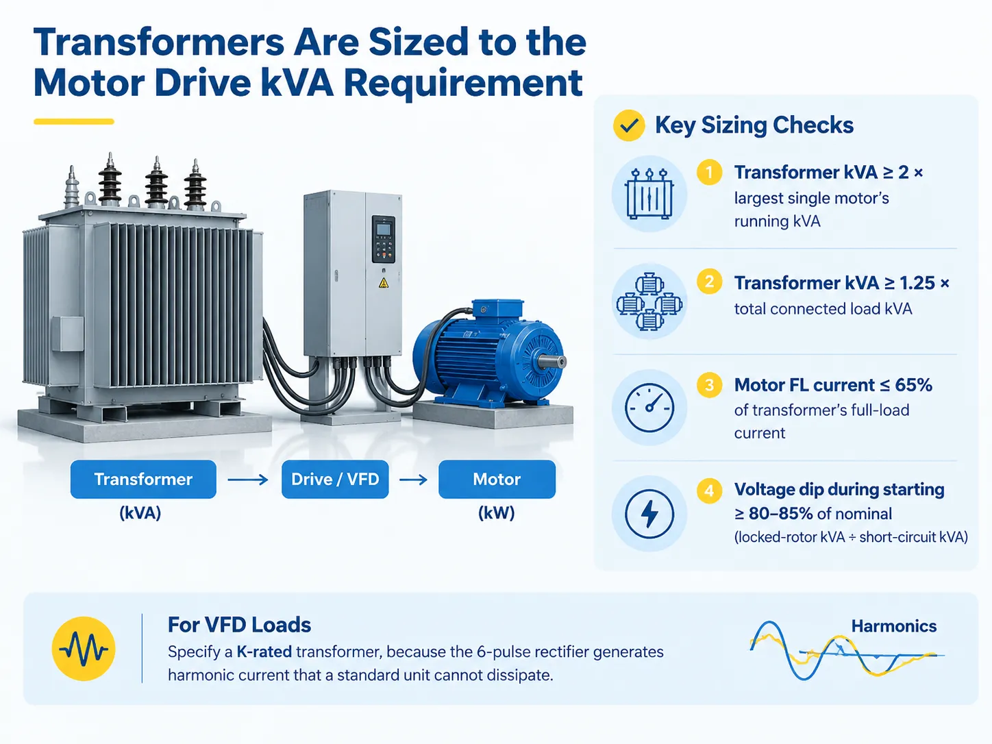
Why Transformers Are Rated in kVA and Not kW
The rating is measured in apparent power as the transformer must handle the whole current irrespective of what the load is connected. The losses are mainly incurred due to current (copper loss as per I²R calculation) and voltage (core loss) which does not matter if the load is resistive or reactive. In the case of a 100 kVA transformer feeding a load at 0.8 power factor, it provides 80 kW while the same transformer providing a load at 0.95 power factor provides 95 kW of power. The current is the same, but the outcome is different.
This is why motor load has to be converted to kW before being compared to the transformer capacity. In a three-phase motor:
kVA =√3×VL-L×I/1000
For single phase, drop the √3. Either way, the calculation is the one thing that has to be right before any of the rules of thumb apply, and the full method including the power-factor assumption is worked through in this guide to calculating kVA for three-phase power.
The reason that the term “sized to the kVA requirement” is more accurate than it appears to be is that the definition includes one value in operation, one value in starting condition and a harmonic component, and the transformer must endure all three values simultaneously.
The Four Numbers a Motor Gives You
Everything downstream comes from four data points, and three of them are on the nameplate. What each means in rating terms matters here, because a motor’s four numbers are not the same four a transformer is specified on — the difference is explained in this overview of what the kVA rating on a transformer actually represents.
| Number | Where it comes from | What it is used for |
|---|---|---|
| Rated output (kW or HP) | Nameplate | Sizing context only — not the transformer load |
| Full-load current (FLA) | Nameplate, or NEC Tables 430.248 / 430.250 | Running kVA, and the 125% conductor sizing |
| Service factor and efficiency | Nameplate | Realistic running demand |
| NEMA code letter | Nameplate | Locked-rotor kVA per horsepower — the starting load |
The NEMA code letter is the one people skip, and it is the one that decides the size. It expresses the locked-rotor kVA per horsepower, and it varies by a factor of seven across the alphabet.
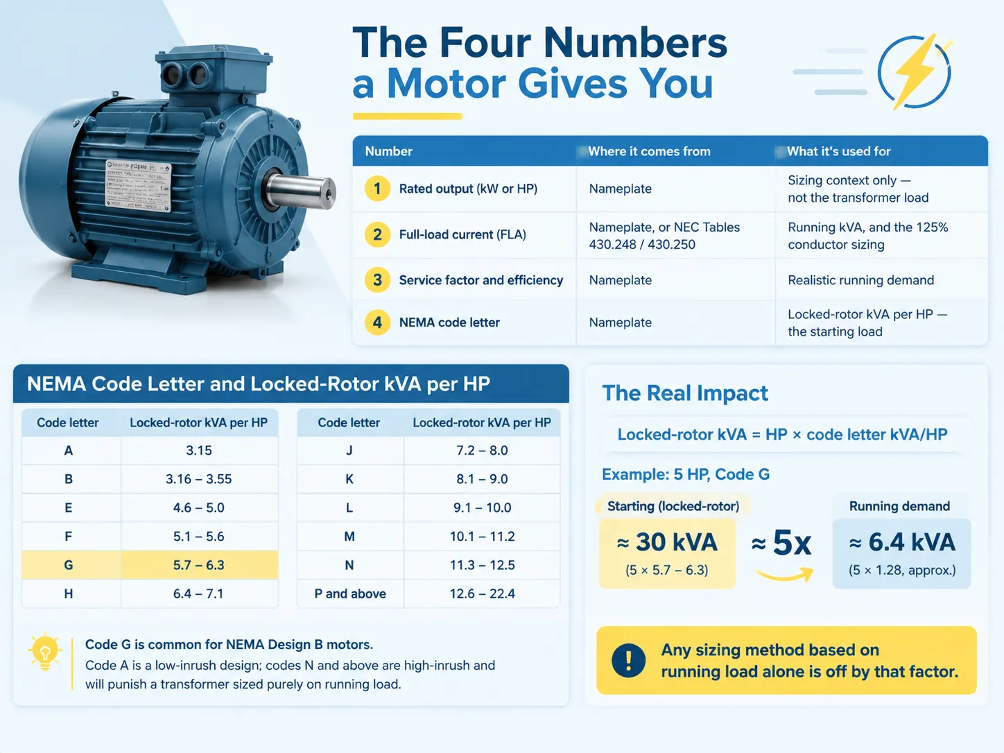
| Code letter | Locked-rotor kVA per HP | Code letter | Locked-rotor kVA per HP |
|---|---|---|---|
| A | 3.15 | J | 7.2–8.0 |
| B | 3.16–3.55 | K | 8.1–9.0 |
| E | 4.6–5.0 | L | 9.1–10.0 |
| F | 5.1–5.6 | M | 10.1–11.2 |
| G | 5.7–6.3 | N | 11.3–12.5 |
| H | 6.4–7.1 | P and above | 12.6–22.4 |
NEMA code G refers to motors that comply with the NEMA manufacturer standards B design, as most industrial motors are designed under those standards as well. NEMA code A specifies a motor that has a low start-up current while codes N and higher categorize motors that will put a lot of strain on transformers designed based on running loads.
The equation locked-rotor kVA = HP × kVA/HP based on the code will give a kVA in this case of 30 kVA for a motor rated at 5 HP of code G, while the running load demands 6.4 kVA, a factor of 5, thus making any calculations based solely on running load wrong by this factor.
Starting Method Changes the Answer More Than Motor Size
The same motor executed in four different ways presents four different load cases to the transformer, and it is here that specification can be improved without investing any money on transformer.
| Starting method | Current multiple of FLA | Approximate starting kVA | Trade-off |
|---|---|---|---|
| Direct-on-line (DOL) | 6–8× | 5–7× running kVA | Full breakaway torque; worst for the transformer |
| Star-delta | 2–3× | 2–3× running kVA | Cuts starting torque to about a third |
| Soft starter | 1.5–4× | 2–3× running kVA | Adjustable ramp, lower mechanical stress |
| VFD | 1–1.5× | 1–1.5× running kVA | Harmonics force a K-rated transformer |
In simple terms, installing a VFD on a direct-on-line motor can significantly reduce the need for transformers and result in costs that are, most of the time, lower than the next biggest transformer available. This is the reason why the starting technique should be considered when sizing, not just when choosing the control panel.
The problem comes from thinking about VFD technology as a way of downsizing the transformer. While the technology eliminates the inrush issue, it creates the harmonics problem. A standard 15 kVA transformer will be overheating due to 5th and 7th harmonics long before the transformer reaches its rated capacity. In this case, K-rated transformer should rather be used instead of a bigger one.
The Three Sizing Rules, and Where Each Comes From
Three guidelines are employed in the field and they deal with unique concerns, while good design respects all three of them.
- The 2× guideline. It states that transformer kVA must be at least 2 times more than the running kVA of the biggest motor. This is the in-field basic factual rule that accounts for locked rotor surge at a direct-on-line startup, simultaneous shafts or auxiliaries starting, and transformer impedance causing voltage drop before the motor starts spinning.
- The 1.25× guideline. It states that transformer kVA must be at least 125% of total load kVA connected. This prevents transformer overload if everything is on.
- The 65% guideline. It states that motor full load current mustn’t exceed about 65% of transformer full load current.
So take the larger value of the above two and do value rule number 3. The rule 2 applies in cases of one major motor, while rule 1 applies if there are a lot of small motors.
| Motor | Running kVA (approx.) | 2× rule | Practical stock size |
|---|---|---|---|
| 3.7 kW / 5 HP | ~5 kVA | 10 kVA | 10 or 15 kVA |
| 5.5 kW / 7.5 HP | ~7 kVA | 14 kVA | 15 kVA |
| 7.5 kW / 10 HP | ~10 kVA | 20 kVA | 20 or 25 kVA |
| 11 kW / 15 HP | ~14 kVA | 28 kVA | 30 kVA |
| 15 kW / 20 HP | ~19 kVA | 38 kVA | 45 kVA |
| 22 kW / 30 HP | ~28 kVA | 56 kVA | 63 or 75 kVA |
Take always the next standard size up after that. The difference in price between one kVA size and the next is small compared to the cost of tool-change transients, accel/decel regenerative systems, and future motor upgrades.
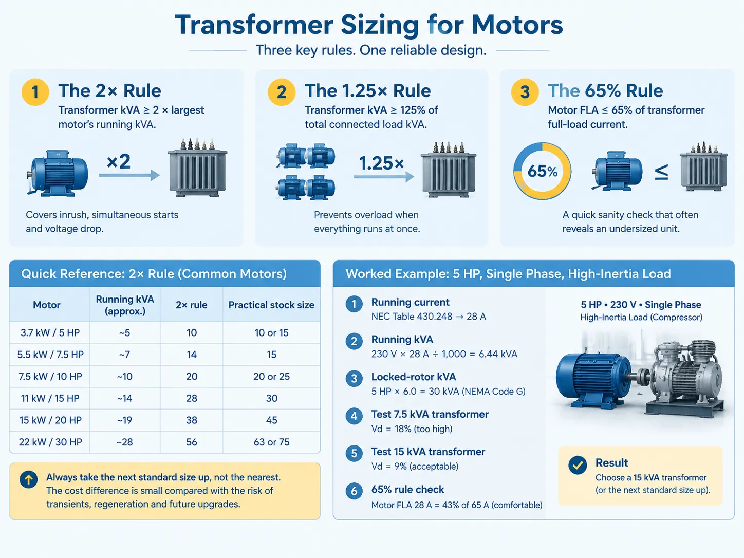
Worked Example: 5 HP, Single Phase, High-Inertia Load
A five horsepower (5 HP), 230 volts (V) single-phase motor powering a reciprocating compressor. Due to the inertia of compressors, the motor stays in the locked-rotor state for several seconds before becoming operational.
- Running current. The National Electrical Code (NEC) Table 430.248 specifies an operating current of twenty-eight amperes (28 A) for the 5 HP, 230 V single-phase motor.
- Running kVA. The formula is 230 volts multiplied by twenty-eight (28 A) divided by 1000 yields kVA equals to six point forty-four (6.44 kVA).
- Name-plate verification. The National Electrical Manufacturers Association (NEMA) Code is G which means it requires five point seven to six point three kVA for each horsepower. Six (6) kVA must be picked to be the average.
- Locked-rotor kVA. KVA equals five HP multiplied by six kVA which is equal thirty kVA.
- Test on a seven point five (7.5) kVA transformer. The impedance is four point five percent (4.5%) hence short-circuit kVA would be seven point five divided by zero point zero four five equals one hundred sixty-seven kVA. Voltage dip equals thirty divided by one hundred sixty-seven equals eighteen (18%).
- Test on a fifteen (15) kVA transformer. The short-circuit kVA is fifteen divided by zero point zero four five which equals three hundred thirty-three (333 kVA). The voltage dip equals thirty divided by three hundred thirty-three equals nine (9%).
- The issue of the 65% rule is an important one. The transformer full-load-current in case of fifteen (15 kVA) transformer is sixty-five amperes (65 A). The motor’s full-load-current is twenty-eight amps (28 A), which means it is forty-three percent (43%) of the other.
The result of the running load was showing that the seven point five (7.5 kVA) transformer works just fine but the starting load requires the fifteen (15 kVA) transformer. The gap between the two is the basic point of the arguments.
A warning regarding the calculations: the voltage dip can be calculated using the formula as Vd = (the inrush kVA divided by the short-circuit kVA of transformer multiplied by 100). A transformer having the per unit impedance of four point five (4.5) has the short-circuit capacity about twenty two times bigger than its capacity, which allows the inrush kVA of thirty (30 kVA) to operate perfectly fine, using the fifteen kVA transformer. Two transformers of the same capacity in kVA may cause different voltage dips due to the different impedance rates.
Worked Example: 10 HP, Three Phase, on a VFD
A three-phase motor rated at 10 HP, 460 V and 14 A full-load current with a VFD is operated.
- The formula to calculate running kVA is running kVA = 1.732 × 460 × 14 ÷ 1,000 = 11.16 kVA.
- When the motor is started using the VFD, it limits the starting current to 1-1.5 times that of the full-load current thus giving starting kVA to be in the range of 11–17 kVA.
- The rule that a safety factor of 2× for the transients is followed still, that is why 2× 11.16 = 22 kVA is used in this case. Hence the actual kVA of transformer used will be 25 kVA.
- The harmonic problem will take its place. The 6-pulse rectifier is producing a distorted current which has strong 5-th and 7-th harmonics. Thus the corresponding transformer has to be rated as K.
- One has to make sure about the neutral wire. The triplen harmonics accumulate in the neutral and do not cancel each other out, thus the corresponding K rating of a transformer must be 200%.
Voltage Dip: The Constraint That Actually Decides
It’s possible for a transformer to be thermally sufficient but still not function properly in application because limiting criteria come down to whether the motor can do its job or not. A NEMA Design B motor can pull 5 to 7 times full-load current when locked-rotored but decreases once it starts turning. If the combined impedance of the feeder and transformer keeps the motor voltage at below 80% of nominal value, breakdown torque will fail and cause the motor to stall.
Using softer options can help solve the issue, given that locating the transformer near the motor will reduce the length of the feeder and lowering the total impedance. When increasing sizing of the transformer, it is important to realize cost savings that result from that. Also, starting method is also among the cheap solutions when the starting method applied is a soft starter (2 to 4 times FLA) and VFD (1 to 1.5 times FLA) used instead.
The acceptable dip number is based on the down-the-line equipment. Motors can experience a drop of around 15 to 20 percent, which they can withstand. Concerning a VFD, it will find the situation much more challenging where voltage drop is around 10 to 15 percent. Therefore, in case VFD and the motor use the same transformer, it is better to be in compliance with the stricter requirement.
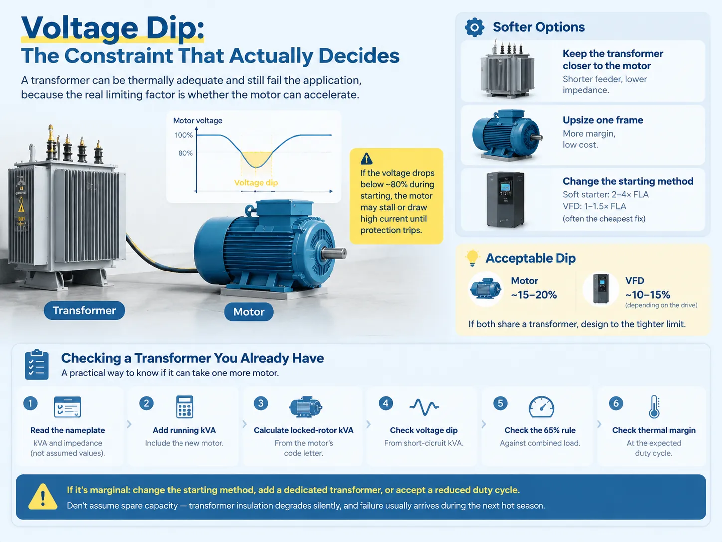
Checking a Transformer You Already Have
Most of the time, retrofit projects do not start from scratch. The task is usually whether the available transformer is able to take one more motor or not.
- First check the nameplate kVA and impedance (not their assumed values).
- Next accumulate the running kVA of the whole load at the secondary side including the new motor.
- Then calculate the largest motor’s locked-rotor kVA according to its starting code letter.
- Proceed to calculate the voltage drop according to the short-circuit kVA of the transformer.
- Then check whether the 65% current rule is obeyed for the total load conducted.
- Lastly check the thermal margin at the anticipated duty cycle not in one spot alone.
When and if the answer is borderline you can decide to take one of three possible steps — change starting method, install a separate transformer for the new motor, or agree to work under reduced duty. What you cannot do is assume that the current transformer has spare capacity just because it has not failed yet — types of insulation degradation is imperceptible, but the result usually follows during the next hot season. The formal version of that assessment is set out in this method for determining whether a transformer meets capacity requirements.
Thermal Margin and the 80% Rule
Transformers are typically operated at around 80% of their rated capacity for continuous operation, which allows for variations in ambient conditions, harmonics losses, and occasional overloading. This is the essence of the “80% rule” of transformer design.
This rule is more relevant when dealing with motors than continuous loads as in the case of motors. The operation of motor loads consists of cycles. For example, a machine tool works with 60% load on average, while there are peaks of 150% during a heavy cut; a compressor operates at 100% until the reservoir is filled, and then it works idly. Thus, all of the scenarios above cannot be described with one mathematical parameter. It is for this reason that the cycle mode usually determines better thermal engineering rather than the kVA rating — it is accompanied by lower temperature increase, improved cooling, and the design of the motor winding tailored for cycling operation. Where that margin comes from and how it is built is covered in this note on improving transformer overload capacity and stability.
Purchasing margin by diminishing impedance has its limitation as well. Lowering impedance reduces the voltage drop, but on the other hand, it increases the fault current at the secondary, thereby increasing the rating of every device in the subsequent circuits. The balance is reached, usually somewhere around 4–6% in case of dry type distribution transformers.
What to Put in the Specification
A motor-feed transformer that can cope with real-life occurrences should consist of the following:
- kVA rating calculated using the three rules and rounded off to the nearest voltage rating available.
- Primary and secondary voltage and tap range needed.
- Impedance explicitly stated — 4% or 6% changes the calculation of voltage dip considerably.
- Vector group and grounding matching the drive and the earthing arrangement.
- K-factor in the case of any VFD used — K-4 as a minimum, and K-13 for drive-dominating loads.
- The specification of insulation class and temperature rise made with Class H insulation and grade F or B rise in the case of cyclic motor duty involved.
- Neutral rating should be set at 200% for K-rated units.
- Duty and overload statement made for anything else besides the nameplate.
Two items here are very often omitted. The first item is impedance that is left to the supplier, so that an important change in starting operation occurs. The second item is K-factor that was missed due to the fact that the drive was specified by another person separately from the transformer six months later.
For a medium voltage motor drive on 6-10kV supply, it is usually a cast-resin dry type, as it is located in a plant room and does not carry oil into the building. The ratings, winding construction and enclosure options for that class of unit are set out in this cast-resin dry-type distribution transformer range for 6–10 kV service.
FAQ
What are the standard kVA sizes for transformers?
In use are two forms of ladder. IEC method follows a R10 method of approximately 25% for each increment, which are acceptable values 100, 160, 200, 250, 315, 400, 500, 630, 800, 1,000, 1,250, 1,600, 2,000, and 2,500 kVA. North American method follows 15, 30, 45, 75, 112.5, 150, 225, 300, 500, 750, 1,000, 1,500, 2,000, and 2,500 kVA. There are low-power devices on both ladders from 10 to 50 kVA, making impossible to control the possible range in different markets with the same requirement: for example, the level 45 kVA can be indicated in one region, while in other – at 50 kVA.
Why are transformers sized in kVA?
Because the current does not know load transducer is straight away affected due to the instantaneous current with time and voltage; meaning this also. In the main concern of all ratings, all kVA is statutory apparent power of the equipment rating without an overheating condition. When looking to compare any motor and transducer ratings, this is also the ideal reason why the kW rating of the motor is to be converted into kVA.
What kVA rating is required for a transformer?
What is the 80% rule for transformers?
The standard practice is that when operating a transformer continuously, it should not be loaded to over 80% of its kVA rating; less than 80% of the rated kVA would allow enough margin for extreme ambient temperature (which the standard temperature is considered to be 30 °C), harmonic losses caused by non-linear loads, and short-term overloading. In this case, it refers to an advice rather than a code, as the real limit is the winding temperature of the transformer, meaning that insulation class and temperature rise are as important as the kVA value.
References
- NFPA — NFPA 70 National Electrical Code, Article 430 motor circuits and Tables 430.248 / 430.250
- NEMA — motor nameplate code letters and locked-rotor kVA per horsepower classifications
- Eaton — transformer sizing, K-factor selection and harmonic loss application guidance
- Schneider Electric — dry-type transformer specification data and motor-load sizing guidance
- Electrical Engineering Portal — transformer sizing and voltage drop calculation for large motor starting
- UL Solutions — UL 1561 dry-type transformers and recognised K-factor ratings
- International Electrotechnical Commission — IEC 60076 series for power transformers and IEC 60034 for rotating machines
- US Department of Energy — motor systems and transformer efficiency guidance
Conclusion
Transformers are selected based on their kVA capability, and care is taken in selecting the proper transformer that factors not only in the kVA size of the electric motor but also its application type (how it will be started) and operation characteristics. The new transformed kVA rating should reflect the total kVA value of the motor, including all electric power sources (e.g. power factor correction/reactive power) and locked rotor kVA (or the ‘worst case’ operating condition). When comparing this to standard induction motors, which typically utilize the two-point replacement method (for kVA rating and locked rotors), there is also another type of kVA, the harmonic current based on a VFD’s ‘K-factor’. When calculating kVA capacity, we also have to factor in a voltage drop, as this may occur (despite the transformer being thermally capable) that might result in insufficient terminal voltage to start the motor. This applies to electric motors ranging from 5HP to 500HP or larger.